Table of Contents
The flowsheet in this study illustrates the general practice in the United Kingdom. A large number of coal preparation plants have been established by the National Coal Board during the past 10 years. The primary consideration is to achieve a maximum recovery of low ash coal. The secondary consideration is to reclaim the plant water and avoid pollution of streams or rivers in the area. The flowsheet incorporates three stages of treatment for the various size ranges, namely, Dense Medium for the — 8″, +2″ fraction, Baum Jigs for the —2″, +½ mm. fraction, and “Sub-A” Flotation for the — ½ mm. fraction. In addition to the low ash coal fines recovered, flotation is an essential part of the flowsheet for preparing coal flotation tailings for media use in the dense medium separation and also to enhance the disposal of the fine refuse or tailing.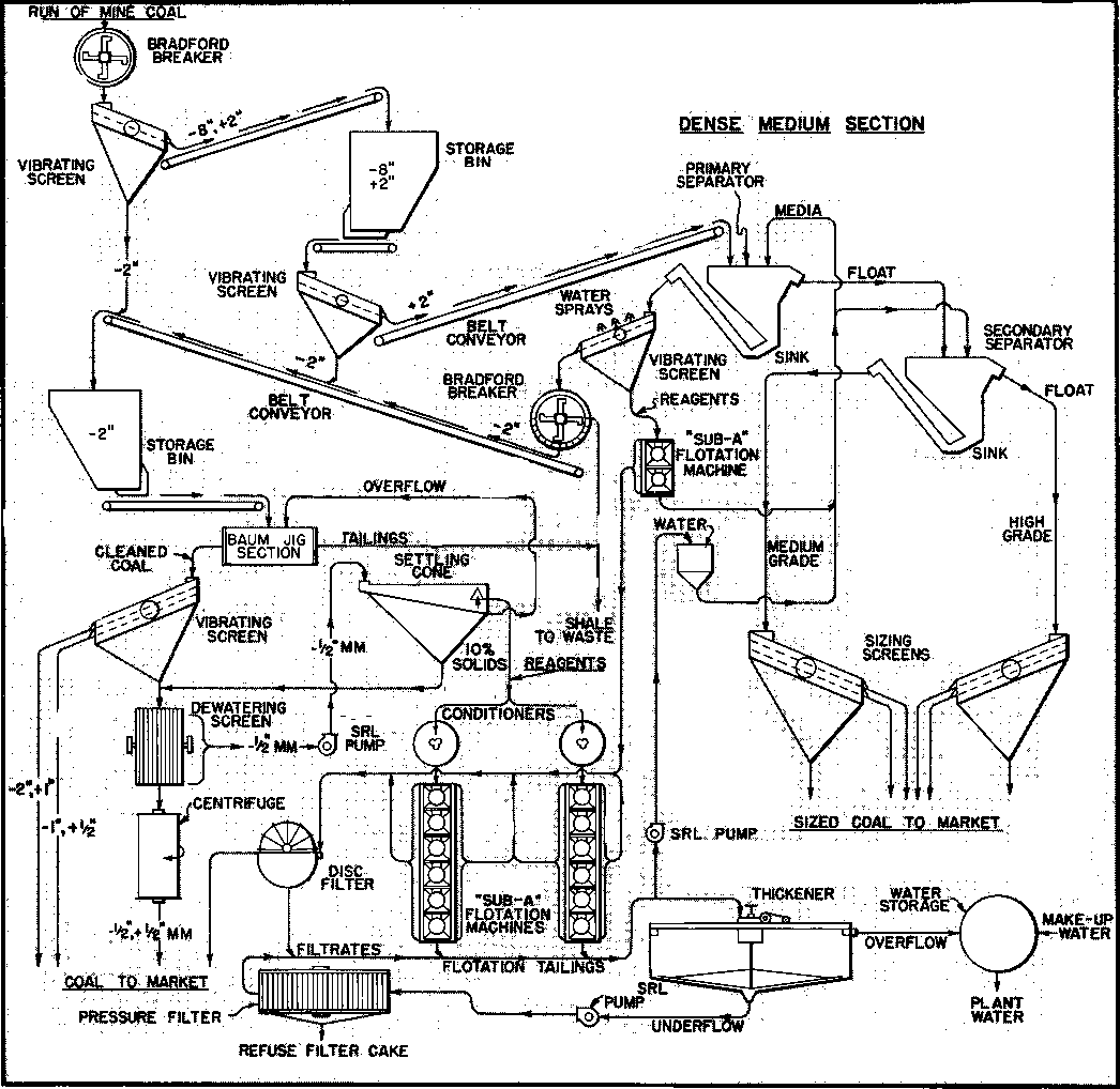
The Flowsheet
Breaking and Sorting: The run-of-mine coal as received from the colliery is reduced by means of Bradford Breakers to approximately 8″ and then screened into plus and minus 2″ fractions.
Dense Medium Section: The —8″, 2″ material is delivered to the Dense Medium Separators which are generally of the deep bath type. In the flowsheet the primary separator delivers the floats to the secondary unit which produces medium grade and high grade coals. The sink product from the primary separator is delivered to a Bradford Breaker fitted with 2″ perforations which rejects the hard shale and reduces the middlings to —2″ for retreatment in the Baum Jig Section. The products from the separators are passed over spraying screens (one shown) and the resultant effluent is treated by “Sub – A” Flotation Machines for the removal of fine coal. Without this flotation step, the fine coal would upset the specific gravity range of the natural media and create a large circulating load of coal fines in the media.
The media is a closely controlled fraction from the tailings produced by the main flotation section with respect to density and size ( — 60, + 250 mesh).
Jig Section: The —2″ fraction from both Bradford Breakers is treated by Baum Jigs and the clean coal screened into various size ranges for marketing. The ½ mm. x 0 is partially dewatered on ½ mm. wedgebar screens and then further dewatered by a centrifuge preparatory to marketing. The underflow from the ½mm. wedgebar screen is pumped to large diameter settling cones for treatment in the froth flotation section.
The refuse from the Baum Jigs is combined with the waste shale from the secondary Bradford Breaker and used for fill.
Flotation Section: The feed for the flotation section is siphoned from the settling cones at 10% solids and is fed to Conditioners. The reagents are added at this point. A mixture of cresylic acid- creosote, which acts as a collector and frother, is used in England.
The separation is made using No. 30 “Sub-A” Flotation Machines equipped with four-bladed froth paddles. At 10% solids each 100 cubic foot of cell capacity will handle 2-3 tons throughput per hour or roughly one ton per 40 cubic feet per hour.
The froth concentrates (cleaned fine coal) are filtered on a Disc Filter and the filter cake combined with either the —½”, + ½ mm. jig product or marketed separately. From an initial feed containing 20 – 25 % ash, the froth concentrate will average 8 – 12% ash and the tailings 80 – 85% ash. These figures, of course, will vary depending on the inherent ash content of the coal.
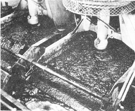
Typical “Sub-A” coal flotation installation in England.
The tailings from flotation are fed to a thickener where a flocculant is usually added to promote settling. The thickener underflow is pumped to multi-framed filter presses for removal of water to a final moisture content of 18-20%. This waste material is trucked to a disposal area.
The filtrate from the concentrate and tailing filters are combined with the thickener overflow water and returned for re-use in the plant.
Remarks
The standard practice on coal in England has been to use cell-to-cell “Sub-A” Flotation Machines of the double overflow type. Several hundred of the large No. 30 cells (100 cu. ft./cell) are in use. Super-charging is not generally used. Flotation is carried out at low solids, usually under 10% dilution.
In the U. S. on bituminous coal the trend is toward open type No. 30 “Sub-A” Cells, single overflow, and with supercharging. Flows of dilute pulp up to 1500 GPM are effectively treated with excellent results through a single 4-cell machine. Capacities up to 7½ TPH of clean coal per 100 cubic ft. cell are not uncommon even on material as coarse as minus 14 mesh. Low ash froth concentrate and high ash refuse can usually be obtained in a simple one pass flotation system.
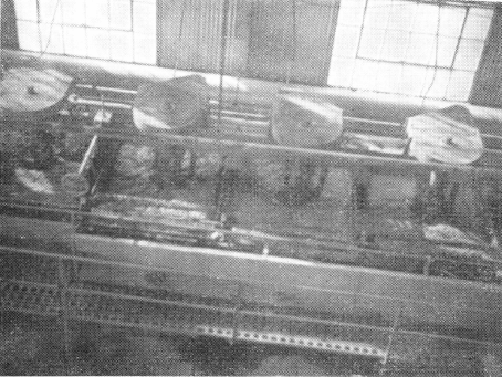
Typical “Sub-A” coal flotation installation in the United States.
American Potash & Chemical Corporation Uses Agitators With 120″ Diameter Propellers in Coarse Leach System
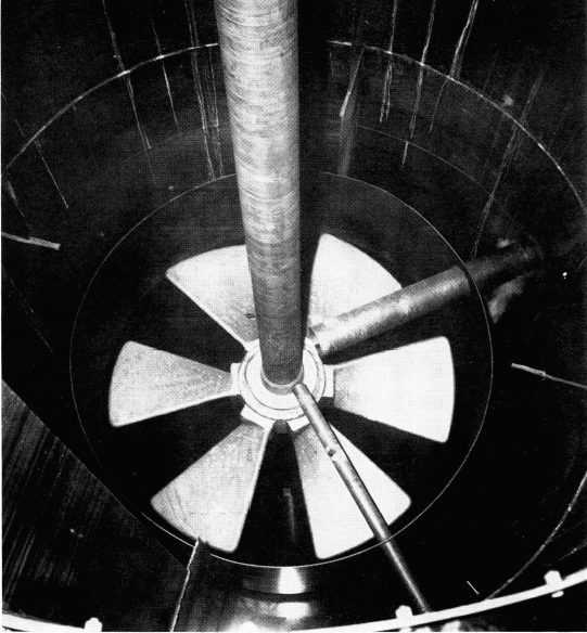
In 1958 the American Potash & Chemical Corporation, Trona, California, installed two 15′-6″ diameter x 28′ high Agitators equipped with 120″ diameter Turbine Type Propellers. These agitators are in parallel and circulate 91,000 gpm of 25% solids slurry. The new feed slurry to the agitators is of 29% KCl and NaCl crystal slurry, 95% +50 mesh.
Each unit consumes less than 20 HP in handling the coarse leach and crystalization service.
This company is highly pleased with the operation of their big Agitators and reports no maintenance problems.
MAJOR ALUMINUM COMPANY USES TUMBLING MILL TO GRIND SPENT POT LININGS
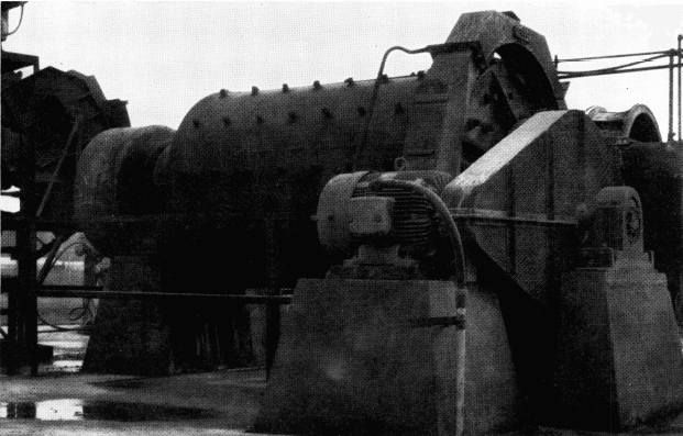
Tumbling Mill in operation at major aluminum company. Mill grinds spent reduction cell insulation to reclaim cryolite.
A major aluminum company selected a 5′ x 8′ Tumbling Mill for grinding their spent reduction cell insulation and other alkaline materials as part of their cryolite reclamation program.
The feed to the mill is —4½” and the discharge is —20 mesh. To reduce iron contamination, no rods or balls or other grinding media are used in the mill. Disintegration of the material is aided by large lifter bars inside the mill.
Feed is introduced to the mill by a large drum feeder designed specially to handle the large feed sizes without clogging.
The feed – end trunnion liner is equipped with a deep spiral to convey the large pieces of pot lining into the mill. The discharge trunnion liner has a reverse spiral to minimize the discharging of oversize material. The mill is equipped with a Spiral Screen on the discharge to scalp out tramp oversize.
This mill operates out of doors and is exposed to varying weather conditions. The company reports their Mill has proven satisfactory in every way.
Phosphate Producer Uses “Sub-A” Flotation and Enjoys Over 6 Years Service From Wearing Parts
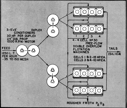
A major phosphate producer in Florida purchased four 4-cell No. 30 (56 x 56) “Sub-A” Flotation Machines in 1954. These machines are on Phosphate Rougher Flotation service (fatty acid section). Feed to this section is 1250 long tons per hour of —35 +150 mesh feed. The machines are still equipped with original neoprene impellers and diffusers which are still in good condition.
This is typical of the outstanding record “Sub – A” Flotation has made in the Florida phosphate area and also in every mineral producing area of the world.
MULTIPLE SAMPLE CUTTERS SAMPLE SEVERAL STREAMS SIMULTANEOUSLY
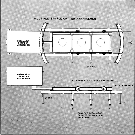
This arrangement can be used to sample any number of streams simultaneously. Amount of each sample can be identical or proportional depending on feed volume and cutter opening. Samples can be combined or kept separate.
This unit is a standard Automatic Sampler Mechanism with special designed cutter arrangement using standard type “B” wet cutters carried on end track and wheels. Cutter openings are adjustable from ¼” to ½”. Cutter travel can be 16″, 21″, 30″ or more. Cutters move at 7½”, 12″, 18″ or 30″ per second and make sample cuts at any interval from 2 to 55 minutes. Timer is adjustable in 1-minute increments. Samplers can be arranged for continuous sampling if desired.
Automatic Samplers are flexible to meet most sampling problems. They are completely automatic and cut samples impartially exactly on time and exactly in the same manner each time.
Coal Flotation with Non-Ionic Surfactants
In coal flotation, the most commonly used collectors are oily materials collectors such as diesel oil and kerosene. For higher rank coals, the reagent consumption in flotation is low because of the high natural hydrophobicity of the coal. However, for low-rank coals (containing a greater amount of oxygen), flotation performance with these oily collectors is poor and large amount of collectors are required in order to obtain acceptable coal recovery.
Polyethoxylated nonyl phenols constitute a major part of the general class of non-ionic surfactants, whose hydrophobic/hydrophilic characteristics can be controlled by varying the number of ethoxy groups on a hydrophobic nonyl phenol.

Experimental Materials and Methods
Two bituminous coals, namely Illinois No. 6 (from Peabody Coal Co., Marissa, IL) and Pittsburgh No. 8 (from R&F Coal Co., Warnock, OH) were used in this investigation. The proximate and sulfur analysis results of these two coals are given in Table 1.
Chemical reagents used in this study are the following:
- Tetrahydrofufuryl butyrate (THF)
C4H7O-CH2OOC-C3H7 - Nonyl phenol (GH0)
C9H19-C6H4-OH - Polyethoxylated nonyl phenols
(GH1.5, GH4 and GH6 for n = 1.5, 4 and 6)
C9H19-C6H4-O-(C2H4O)nH - Nonyl benzene (GHB)
C9H19-C6H5 - Dodecane
C12H26 - 4-methyl-2-pentanol (MIBC)
(CH3)2CH-CH2-CHOH-CH3 - PEG (200) monolaurate (ELA)
C11H23-COO-(C2H4O)4.5H
Results and Discussion
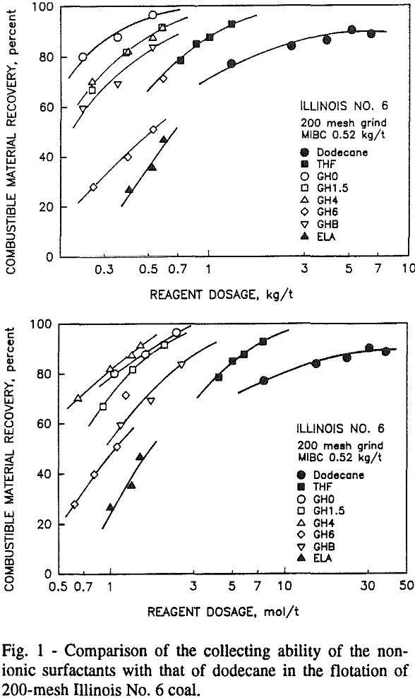
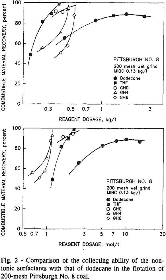
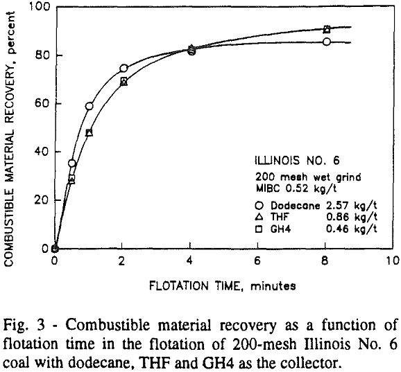
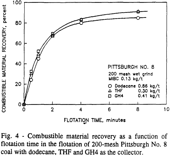
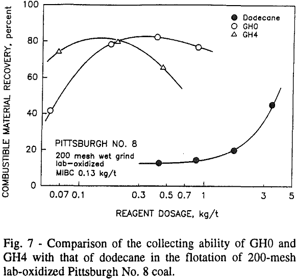
To obtain comparable combustible material recovery, the GH series of reagents with lower numbers of ethoxy groups require a considerable lower amount of reagent than for dodecane.
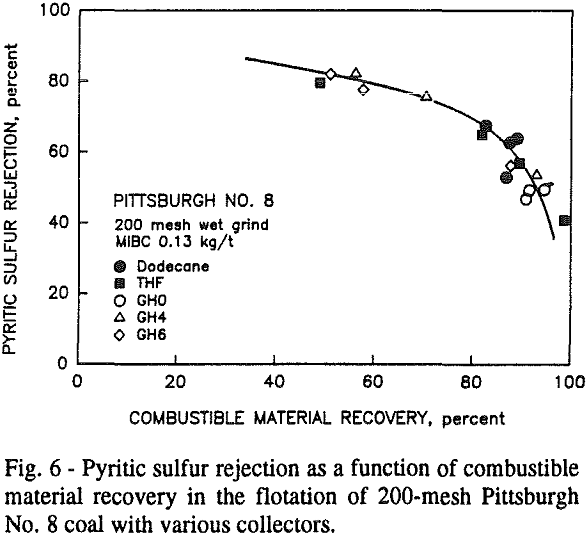
Since the non-ionic surfactants contain a relatively small portion of polar groups in their structure, the flotation results for both coals indicates that these polar groups may play an important role in the interaction of the reagents with the surface of the coal. This interaction may be enhanced if the surface of the coal contains numerous oxygenated groups, as in the case of Illinois No. 6 coal or a coal that has been weathered. Because of this, the non-ionic surfactants can spread on a hydrophilic coal surface much more easily than the oily collector dodecane, thereby creating a hydrophobic surface.

Summary and Conclusions
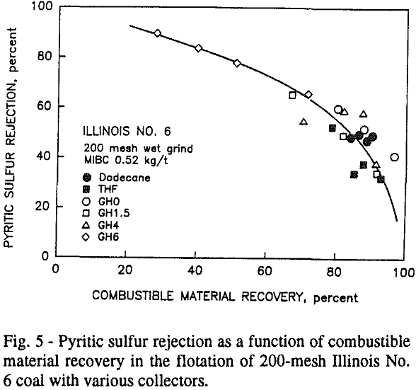
The flotation results of Illinois No. 6 and Pittsburgh No. 8 coals show that non-ionic surfactants GH0, GH1.5, GH4 and THF are more effective collectors than the oily collector dodecane for both unoxidized and oxidized coals. Although ethoxylated (with an average of 4.5 ethoxy groups) dodecanoic acid has a similar balance of hydrophobicity and hydrophilicity, it was a poor collector.

