Table of Contents
The Air-Quenching shaking grate Clinker Cooler was developed more than 20 years ago as an improved heat recuperating cooler for use with rotary kilns. It was designed to air quench and cool large quantities of hot clinker rapidly, and to recover and return to the kiln a major portion of the heat from the clinker.
It was immediately successful in the cement industry. The capture of secondary combustion air above the cooling clinker was a big forward step in achieving better rotary kiln economy and fuel utilization. Besides fuel savings, clinker grinding costs were substantially reduced. In many cases it was found that a quick-quench clinker was much easier to grind. Subsequent experience showed that the Air-Quenching cooler resulted in lower power and maintenance costs than could be obtained with any other cooler.
The lime and chemical industries have also adopted the Air-Quenching clinker cooler as a practical,.cost-reducing way to cool hot material from a rotary kiln. It can handle both fine and coarse materials. Dusting is kept to a minimum because there’s large grate area and the bed of material on the grate is thin and uniform, requiring only low velocity air for cooling. Material to be cooled is conveyed and agitated and, at the same time, subjected to a blast of cooling air. Conveying action is imparted to the entire cooler, including the integral windbox.
The Air-Quenching grate cooler is simple in design and operation. The entire cooler is composed of a single operating unit. The upper portion acts as a hot air collecting chamber above the grate for returning preheated air to the kiln and venting excess air to atmosphere.
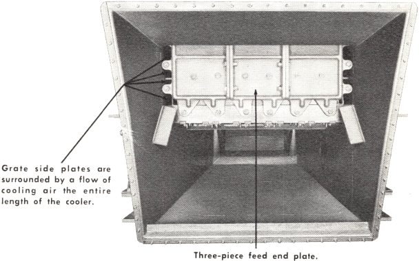
This portion is an independent stationary housing, built of easy-to-install refractory brick and heavy steel framing. It is completely insulated. The suspended flat arch feed throat extending from the level of the burner floor to the cooler is also furnished.
The lower portion of the cooler, including the grates, reciprocates and serves as the cooling chamber. It is supported on inclined arms and spring assemblies, bracket mounted on heavy steel bed plates designed to be embedded in a concrete foundation.
Tested Before Shipment
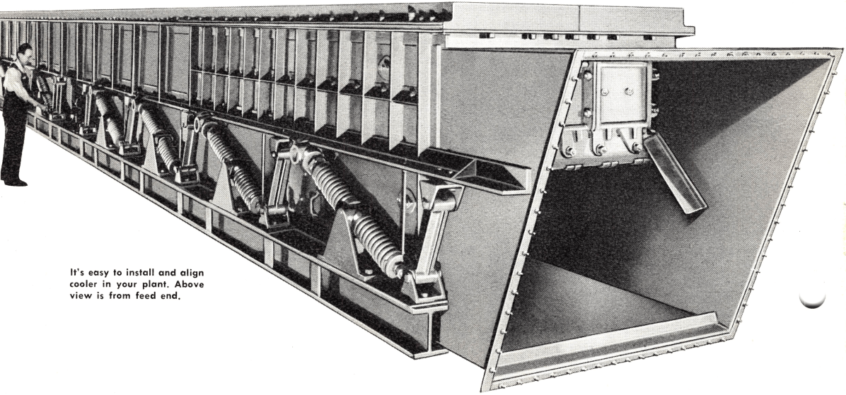
Air-Quenching coolers are assembled and shop-tested before shipment. Thus, any corrections required are made before your cooler leaves the factory. Your cooler arrives at your plant ready for installation.
Clinker Cooler Installation Costs
Arrives in Only Two Sections—The Air-Quenching cooler usually arrives at your plant in two sections, each section completely assembled. With so few parts to be lined up and bolted together erection can be accomplished in a minimum of time with a small erection crew. Even the refractory brick for the stationary air housing is furnished.
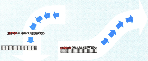
Fits Existing Plants — The Air-Quenching cooler fits readily into existing kiln arrangements because of its horizontal design. It requires only 12 feet of headroom and can be installed at right angles to the kiln or on the centerline of the kiln, straight-away or back-under, as illustrated below. Installation and construction costs are low.

How shipment of 4½ by 70 ft. Air-Quenching cooler is made in two pre-assembled sections.
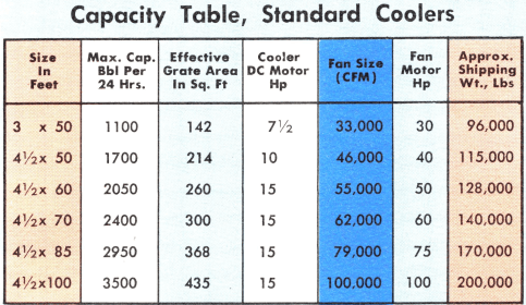
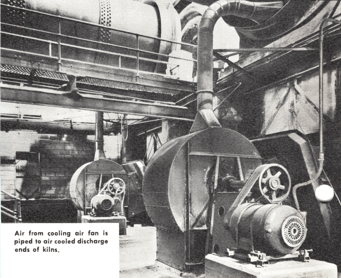
Standard Air-Quenching coolers are built in 50, 60, 70, 85 and 100 ft lengths and 3 and 4½ ft widths to meet virtually all capacity requirements. Non-standard lengths can be supplied on special request. Air-Quenching coolers are furnished complete with dc motor, V-belt drive, starter, stationary air housing, refractory brick, cooler fan, fan drive motor, V-belt drive, starter for cooling air fan, instruments and controls.
You Save Up to 25% less power is required to operate an Air-Quenching clinker cooler! Power consumption, in fact, runs only about ½ hp hour per barrel of clinker.
Cools and Conveys at Same Time
The reciprocating motion of the Air- Quenching cooler moves the material along the grate, from the feed to the discharge end, by an alternating forward-up-ward and downward- backward stroke.
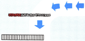
During the forward-upward stroke, the entire grate and bed of material moves forward and upward at the same time.

On the downward-backward stroke, the grate drops away from the bed of material more rapidly than the fall of clinker due to gravity.

Clinker Cooler Power Costs
Low Pressure Fan Requires Little HP — Smooth, reciprocating motion of the cooler results in a uniform bed of material on the grate. A relatively thin, uniform bed requires less air pressure for penetration. The undergrate air pressure of the Air-Quenching cooler is only 2½ in. water gauge; only a low pressure air fan is needed. With less hp required, you have lower power costs! Low air velocity through the clinker bed also results in less dusting.
No Auxiliary Power Requirements — Another reason for low overall power requirement is the fact that no auxiliary equipment such as a dust conveyor is needed. What little material falls through the grate is conveyed along the bottom of the wind box to the discharge end where it rejoins the main clinker stream.
While the clinker is falling, the forward-upward stroke is again repeated, starting the next cycle. In this way the clinker is moved toward the discharge end without damaging abrasive action to the grate.
Clinker Cooler Operation
The Clinker Cooler operates at 260 to 325 strokes per minute – stroke varies from 0.6 to 1. inches. Manual speed control makes it possible to maintain proper cooling conditions under varying loads.
The smooth conveying motion results in a continuous agitation and turning of the clinker bed without excessive degradation. The clinker distributes itself into a uniform bed depth throughout the entire width and length of the smooth horizontal grate surface. Shaking action is gentle.
No Fines Conveyor
The entire cooler including the windbox moves as a unit and in this manner any fines falling into the windbox are conveyed to the discharge end where they rejoin main clinker stream. No special fines conveyor is ever required.
Operating records show maintenance costs, with an Air-Quenching cooler, run as low as 1/10 cent per barrel of material cooled! With proper operation of the cooler, there is little maintenance required.
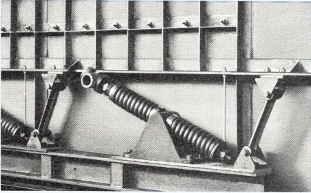
Simple Coil Spring Assembly
Reciprocating motion is controlled by opposed coil springs arranged in assemblies and attached to the sides of the cooler body. These travel control spring assemblies absorb the energy built up at the end of each stroke and return it on the opposite stroke. All motion at this point is merely compressing and releasing the springs. No wear takes place and no lubrication is required.
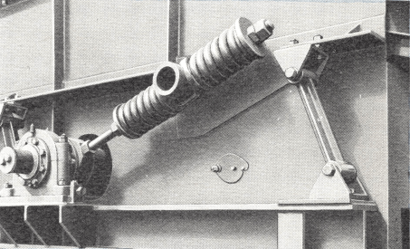
Drive Mechanism Assembly
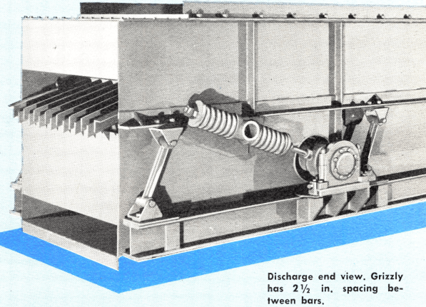
Driving motion is imparted to the cooler by means of a totally-enclosed, roller bearing equipped eccentric shaft driven by a motor and V-belt drive. Buffer springs between the drive mechanism and the cooler body eliminate shock and limit the load on the drive mechanism. The illustration above shows the shock-resisting buffer springs and end of shaft with driving sheave removed.
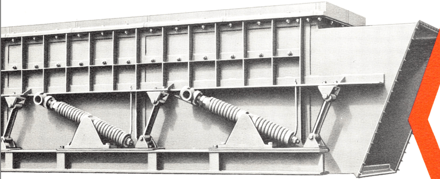
Heavy Reinforced Side Members
Special reinforcing of the cooler body at the feed end prevents side warpage and gives rigid support to the side plate and feed end liners.
Clinker Cooler Maintenance
Little or No Wear — The reciprocating motion of the entire cooler grate and wind box is dampened and limited by flexible rubber bushings and springs. These parts experience little or no wear and seldom, if ever, need replacing. Support arms are heavy steel castings equipped with torsional rubber bushings. No lubrication needed. In fact, the only lubrication required on the entire cooler is four grease fittings on the main drive. The entire drive, with its antifriction bearings, is totally-enclosed. Bolts, travel control springs and rods, and support arm rubber bushings last indefinitely.
Little Grate Wear — Grate wear, too, is negligible. Grate sections, fitting snugly, have flush horizontal surfaces the full length of the cooler. Clinker is moved smoothly along as a ’’live” load by reciprocating motion. Abrasive action on the grates is virtually eliminated.
The Air-Quenching cooler is designed to recuperate over 75% of the sensible clinker heat and return it to the kiln as highly preheated secondary air for more efficient combustion.
Designed for Accurate Control of Cooling Conditions

Designed for Effective Air-Quenching
This illustration shows how hot material from the rotary kiln is uninterrupted as it drops on the feed end of the cooler grate. At this point the up-blast of air, always coolest nearest the source of supply, insures effective air-quenching of the clinker.
Movable Baffle Isolates Air from Hot Zone
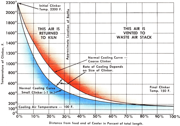
Pre-heated air returned to the kiln does not come from the full length of the cooler. A movable baffle located in the stationary air housing above the grate makes it possible to return only the hottest air back to the kiln. Proper combustion and better fuel utilization can always be obtained.
Clinker is Efficiently Air-Quenched
Notice that hot clinker falls directly on the cooler grate and is air-quenched at once. Clinker does not anneal. Reciprocating movement of cooler results in an immediate, uniform distribution and a true continuous flow of clinker over the grate. A thin, even bed approximately 4-in. in depth results in a better distribution of air through the clinker. Final temperature of minus 1 in. clinker is approximately 100° F above that of the cooling air.

Rotary Kiln Fuel Costs
Recovers Hot Secondary Air — A movable baffle inside the stationary air housing and above the cooler grates divides the cooler housing into two distinct chambers. In this way the hottest air, rising from the hottest clinker at the feed end of the cooler, is isolated and directed back into the kiln. At the same time, the lower temperature air is directed to the cooler vent stack.
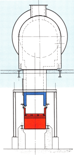
Cooler, Air Housing and Structure
The Air-Quenching cooler is supported on H-beams embedded in a solid concrete foundation. The stationary air housing is suspended above the cooler with a slight clearance, to allow for the cooler’s motion. A special cast iron seal prevents air leakage between the bottom of the air housing and the top of the cooler.
How Heat Recovery Saves Fuel
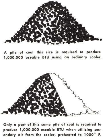
The illustration above show the substantial fuel savings you’ll get with an Air-Quenching cooler. The quantity of air being returned to the kiln can be changed by repositioning the movable baffle in the stationary air housing. This control makes it possible to get better efficiency of the entire kiln-cooler installation. Capacities of grinding mills handling hard-to-grind clinker have been increased as as 10% with the installation of an Air-Quenching grate cooler!
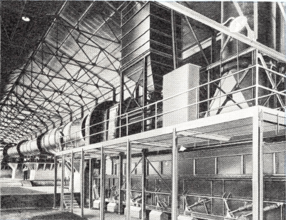
Air-Quenching grate coolers have earned an excellent reputation for dependable service in all parts of the world.
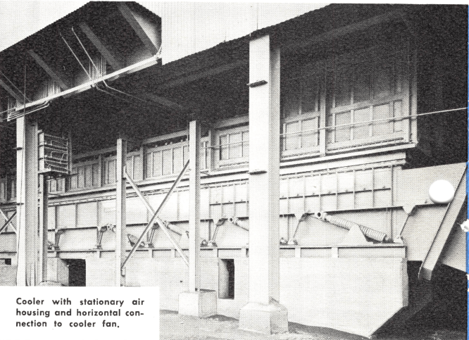
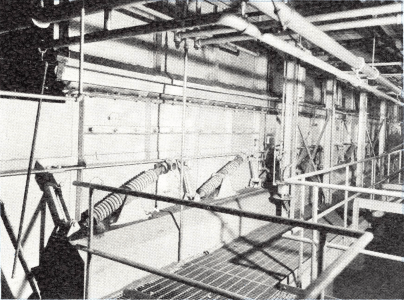
A modern 4½ x 70-ft Air-Quenching grate cooler in a US cement plant. A cooler this size will cool clinker at a rate of 100 barrels per hour.
Clinker Grinding Costs
Rapid Air-Quenching — Clinker from an Allis- Chalmers grate cooler is a true air-quenched clinker, having favorable grinding characteristics. Hot clinker from the kiln is cooled rapidly, not gradually. It does not anneal. Experience has shown that an air- quenched clinker is easier to grind, with consequent savings in the cost of clinker grinding.
Relieves Magnesia Trouble — In cement clinker, air-quenching also helps nullify the detrimental effects of magnesia in the clinker. Rapid air-quenching keeps magnesia combined in an inert state.
Cooling Curve for Average Clinker
A simple conveyor pan can be easily attached to the Air-Quenching cooler for a fraction of the cost of installing a separate conveying unit for delivery of clinker from cooler discharge to storage.
Conveying Motion — The conveying motion of the cooler is imparted to the conveyor pan. Clinker continues moving along the pan from cooler to storage, greatly simplifying clinker handling problem.
No Fines Conveyor — No separate conveyor is needed below the grate. Fines are conveyed along the windbox and rejoin main product stream at discharge end of the cooler.
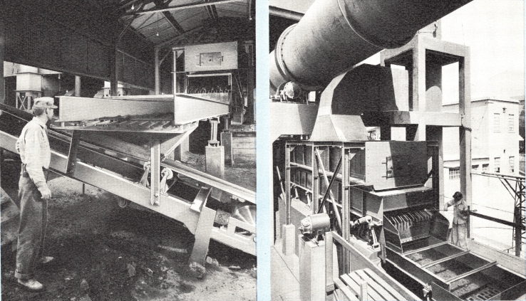
A simple auxiliary conveyor pan conveys both fines and cooled clinker away from discharge end of cooler. Conveying action is continued on conveyor pan.
Heat Resisting Grates
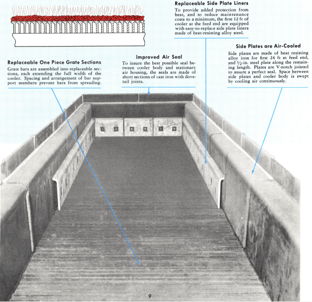
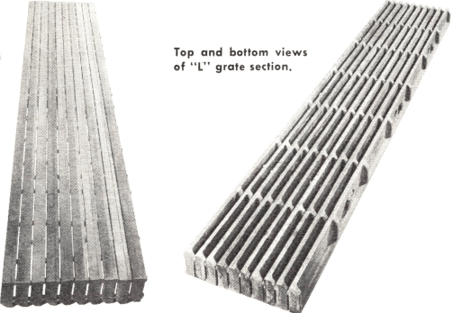
Grates for Air-Quenching coolers are designed for long life and ease of replacement. The first five feet of the grates at the feed end of the cooler are of heat-resisting alloy steel “T” sections 2½ -in. thick. These provide a strong, rigid carrying surface to withstand high temperature material from the kiln, and a rigid surface to withstand the shocks of occasional large lumps of clinker or kiln lining discharging from the kiln.

Top view of “T” grate section.

Bottom view of “T” grate section.
The next 19 ft of grates are 2½-in. thick “L” sections made of alloy heat-resisting iron. The balance of the cooler grate is composed of a series of “L” shaped cast iron bars properly spaced for the passage of cooling air.
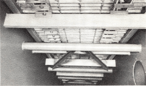
Above—Grates are well-supported on the cooler body. There are no cantilever sections to sag and bind from the high temperature of the clinker.
Cooler is Furnished with all Controls and Indicators
The Air-Quenching cooler is furnished complete with all necessary controls and instruments for regulating the operation and speed of the cooler.
- A safety limit switch to protect the cooler against damage which might be caused by accidental over-speeding.
- A manual speed controller to maintain a uniform bed of clinker on the cooler grates. Cooler speed is adjusted through a field rheostat.
- A manually operated remote cooler fan damper controller and position indicator permits adjusting the damper from kiln operating floor.
- A tachometer for indicating cooler speed.
- A cooler air flow indicator installed in the cooler fan inlet indicates the quantity of air flowing to cooler.
- An indicating gauge for undergrate air pressure, marked for 0 to 4-in. WG pressure range.
- Ammeters for cooler drive and fan motor.
- Push buttons with pilot lights.
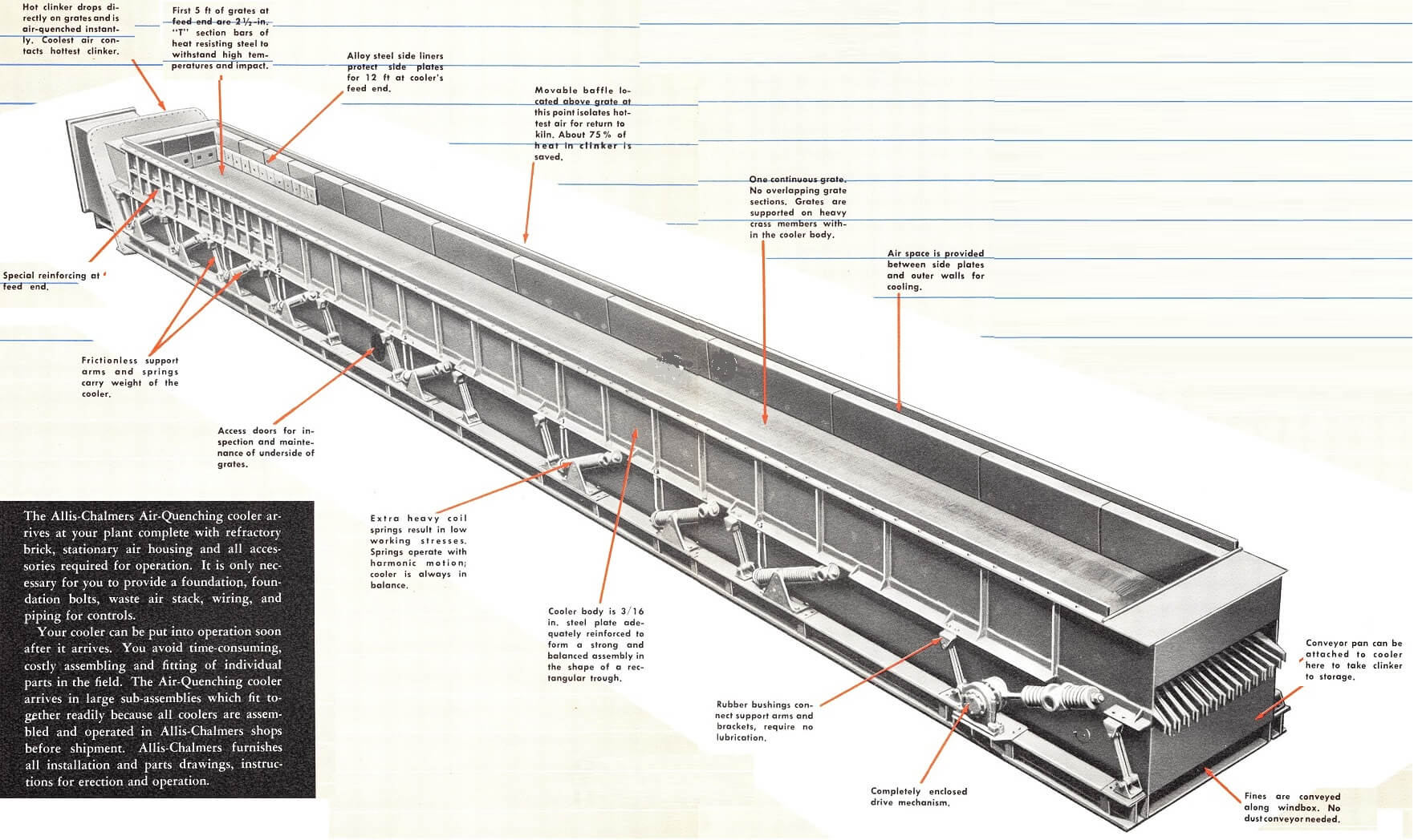
The Air-Quenching cooler arrives at your plant complete with refractory brick, stationary air housing and all accessories required for operation. It is only necessary for you to provide a foundation, foundation bolts, waste air stack, wiring, and piping for controls.
Your cooler can be put into operation soon after it arrives. You avoid time-consuming, costly assembling and fitting of individual parts in the field. The Air-Quenching cooler arrives in large sub-assemblies which fit together readily because all coolers are assembled and operated in out shops before shipment. Furnishes all installation and parts drawings, instructions for erection and operation.

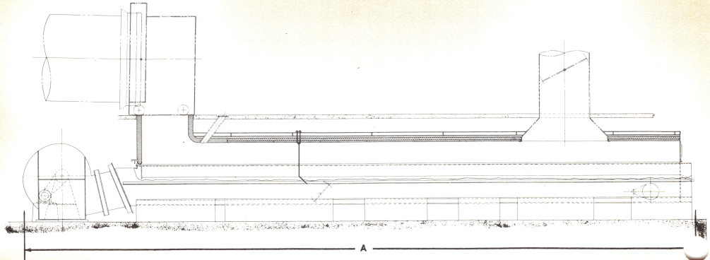
Little or no plant remodelling expense is called for when an Air-Quenching grate cooler is installed. This feature alone may result in a saving of thousands of dollars in your plant.
It is possible to modify the height of foundation and the length of the connecting throat to firing hood. In fact, the Air-Quenching grate cooler can be inexpensively adapted to the conditions of any existing plant.
Send in a drawing or sketch of your plant layout. Our engineers will be glad to show you how the Air- Quenching cooler will fit your requirements.

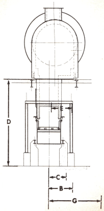
Clearance required for removal of cooler mechanism — either side.
Average clinker cooler space requirements
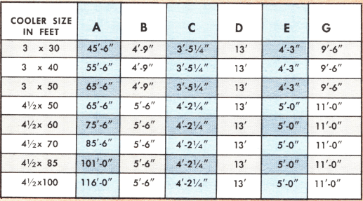
Dimensions shown are for standard cooler sizes. Minimum dimensions can be modified slightly to fit specific installations.
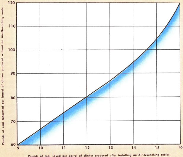
Figure Out for Yourself How Much an Quenching Cooler Can Save for You
IT’S EASY to estimate just how much fuel saving you can expect with an Air-Quenching clinker cooler. Use the graph below to calculate what your costs will be using a cooler as compared with a rotary kiln installation not having facilities for recovering the heat carried away with the clinker.
The vertical scale of the graph shows the pounds of coal consumed per barrel of clinker produced in rotary kilns where heat from the clinker is not recovered. The horizontal scale of the graph shows the number of pounds of coal you will save per barrel of clinker after installing an Allis- Chalmers Air-Quenching clinker cooler. Savings are roughly parallel when using fuels other than coal.
Actually, the cost of an Air-Quenching cooler is not an expenditure at all, it is an investment. In terms of more profitable operation, an Air-Quenching cooler will pay for itself several times over during the life of the unit. This has been demonstrated in dozens of plants where these coolers have been installed.
How Air-Cooling Keeps Kiln End Cool
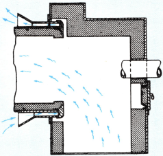
With Air-Cooled kiln end, entire volume of air entering kiln is pre-heated. Cold air circulates around outside of shell only. Result is appreciable fuel savings.
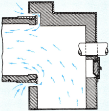
In cooling conventional kiln end, cold air dilutes pre-heated air inside the kiln if aircooling is done as shown above. Fuel is wasted.
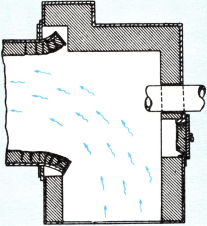
With conventional kiln end sealed to utilize pre-heated air, kiln end becomes badly distorted, refractories loosen. Frequent brick replacement is necessary.
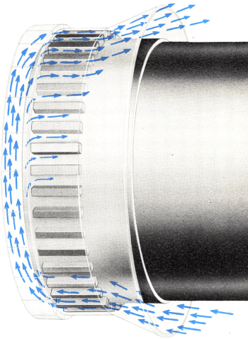
Discharge ends of rotary kilns equipped with Air-Cooled kiln ends stay cool, round and rigid. Cooling air circulates around outside of kiln’s discharge end, and on underside of nose castings, as shown in the illustration. Refractory brick at discharge end lasts longer because Air-Cooled end eliminates warpage or end distortion.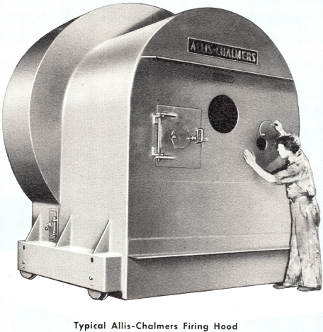
PAYS FOR ITSELF IN 2 TO 3 YEARS
Operating records show that savings in refractory brick alone will pay for the cost of a kiln end in 2 to 3 years of kiln operation! Rotary kilns now in service can be modernized with the installation of an Air-Cooled discharge end.
MAINTENANCE SAVINGS
With no loss of valuable production time to replace end brick, maintenance savings mount fast! Besides savings in refractory brick, an Air-Cooled discharge end will bring you big savings in labor and downtime and elimination of overtime charges to replace end brick.
FUEL SAVINGS
Because the discharge end will not distort, the air seal between the firing hood and the kiln continues to be effective after years of service. Fuel savings result when the temperature of the air inside the kiln is not decreased by infiltering cold air.
ANOTHER excellent way to modernize a rotary kiln is to install a movable firing hood. These modern firing hoods have been designed to be easily adjustable to compensate for expansion and contraction of the kiln. Also, the roller- equipped type facilitates kiln maintenance. 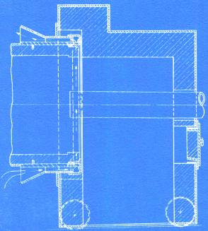 These hoods maintain a tight air seal with the kiln end, keeping cool air out and reducing hot air loss.
The firing hoods are built to use standard refractory brick lining a time and cost-saving advantage. Access and inspection openings simplify inspection and maintenance. All firing hoods are built heavily, to maintain their alignment with the kiln after years of service.
View showing movable firing hood with Air-Cooled discharge end. We maintain unexcelled shop facilities, not only for the manufacture of rotary kilns, coolers and all auxiliaries, but also for the manufacture and speedy delivery of maintenance parts for these products.
And — We manufacture all related equipment, such as pumps, motors and control, switchgear, drives, transformers, right in its own shops. You get undivided responsibility for the efficient operation of your equipment from one company when you specify us.
We will be glad to discuss your equipment problems with you.
https://www.youtube.com/watch?v=uXa4NDbQHpw
