Table of Contents
Proper scaling is necessary for safe operation during any underground mining activity. This need is documented in the mandatory regulations for scaling found in 30 CFR 57. In many U.S. mines operating today, scaling is accomplished by manually barring-down the loose material from around the mine opening. Barring-down requires a great deal of physical strength, endurance, and judgment to safely scale an underground opening. In addition to being one of the most physically demanding activities underground, it is one of the most dangerous. As recent accident statistics indicate, a large percentage of the “fall of ground” accidents and fatalities is directly related to manual scaling. Consequently, safer scaling practices are needed within the mining industry.
In addition to the definite safety hazard, adverse economic factors are also associated with manual scaling. Lost-time accidents and fatalities represent a significant direct cost in terms of the loss of skilled miners and a more indirect cost in terms of increased premiums on Workman’s Compensation insurance. Despite the recent trend toward mechanization in underground mining systems, scaling remains primarily a manual operation. Further, it can be a very time- and labor-consuming process. Hence, as labor costs increase, the cost of scaling using current practice will become an increasingly larger percentage of production costs.
These safety and economic considerations point out a definite need within the underground mining industry for mechanized scaling systems. This need has promoted the development of such systems in the large, room-and-pillar, metal/nonmetal mines in the United States and Europe. However, the mechanized scalers currently available are very large; thus, their use is limited to only the larger-scale underground mining operations. A need remained for a scaling tool that can work in the smaller openings typical of most U.S. mines. To meet this need, the Bureau of Mines contracted with Battelle, Pacific Northwest Laboratories, to develop a mechanized scaler for the smaller sized mines.
Phase 1 of the project entitled Development of a Mechanized Scaler involved assessment and preliminary design of two mechanized scalers. Preliminary designs were successfully completed for both machines. These designs included chassis, highly articulated booms, and combination claw-hammer scaling tools, for use in mine openings ranging from 8 ft x 8 ft to 12 ft x 14 ft. As originally scoped, Phased II was to include detailed design of one of the scaling machine designs completed during Phase I. Subsequent funding restrictions, however, limited Phase II efforts to further development of a unique combination claw-hammer concept that emerged during Phase I.
This report documents the design, fabrication, and testing of a prototype combination claw-hammer tool for machine scaling. The design work was performed at the Richland, Washington, facilities of Battelle, Pacific Northwest Laboratories. Prototype fabrication and quality assurance testing were done by Advanced Industries, Inc., of Portland, Oregon. The preliminary field tests were conducted at the USBM Spokane Mining Research Center, Spokane, Washington.
Claw-Hammer Scaling Tool
Most mechanized scalers are of two types. The first type uses a hydraulically actuated hook or claw to pry loose rock from the mine opening. Machines of this type use the “brute force” approach to scaling. The second type uses a hydraulic impact hammer to remove the loose rock. Most of the hammers are generally quite large, in the 500 to 1000 ft-lb range, and remove the loose rock by impact force and, to some extent, by wedging action.
The success of any type scaling tool is largely dependent on the type of rock in which it is working. Claw-type tools tend to work best in laminated or slabby ground where it is easy to get behind a loose slab and pull it down. On the other hand, the impact hammers appear to work better in more blocky ground where cracks and fractures are not as accessible. Mine operators have expressed concern that the large impact hammers currently being used may tend to damage the roof. Although most operators using the impact hammers reported feeling this problem was not significant, they did admit that the large hammers can actually mine the opening.
The evident limitations of both “brute force” and powered scaling, when used independently, suggested combining the better features of both into a single assembly. Such a combination could be used in a wider range of mine sizes and in various and changing rock conditions.
The claw-hammer assembly developed by Battelle offers the combined versatility of a hydraulically actuated claw for prying down scale and a small hydraulic hammer for chiseling down scale. The major components of the claw hammer are illustrated in Figure 1. Table 1 lists the overall specifications of the claw hammer. The assembly’s small size and light weight allows it to be boom-mounted on a vehicle small enough to negotiate the smaller underground mine openings.
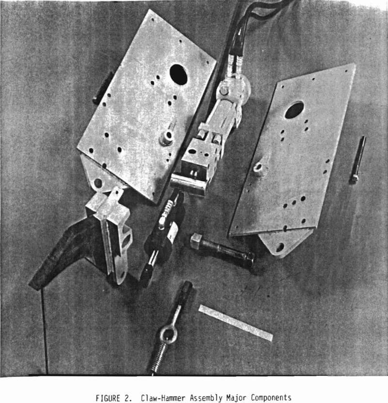
The claw and the hydraulic hammer are structurally supported and protected by the two side plates. The hammer is clamped between the side plates with through bolts. Additionally, the upper spring anchor and the lower protective plate help to cross-tie the side plates. These features are shown in Figure 2, an exploded view of the components.
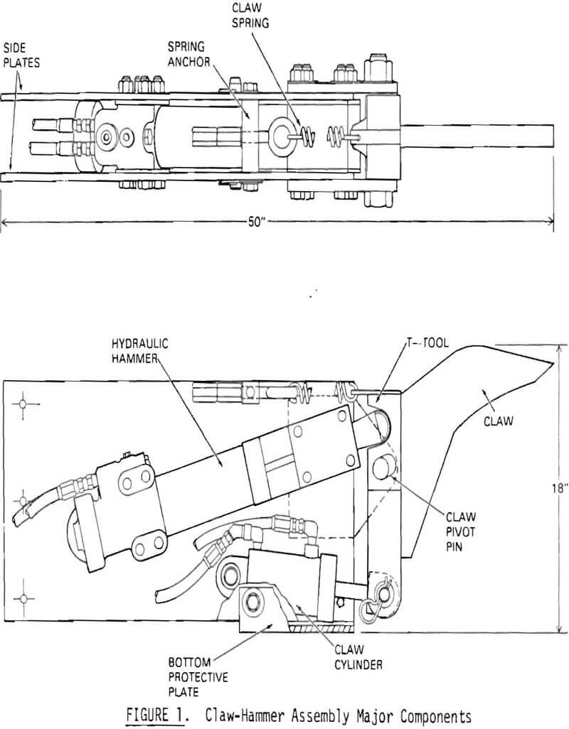
The claw (Figures 3 and 4) is retained between the front of the side plates by a pivot pin through a slot in the claw; the slot is slightly longer than a hammer stroke. A hydraulic cylinder is attached to the lower end of the claw through a clevis arrangement and is pinned to the side plates at its other end. When retracted, the cylinder causes the claw to rotate about the pivot pin to provide the necessary prying motion of the claw’s tip. The
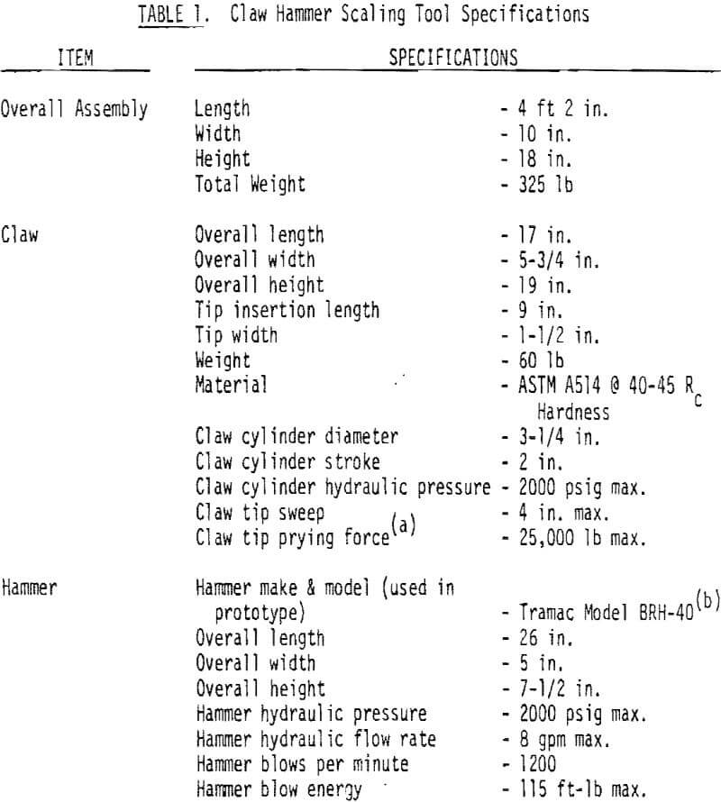
(a) This figure assumes maximum cylinder retraction force leveraged with the claw’s fulcrum point 9 in. from the working tip of the claw. It also ignores any boom reaction forces.
(b) Reference to specific brands, equipment, or trade names in this report is made to facilitate understanding and does not imply endorsement by the Bureau of Mines.
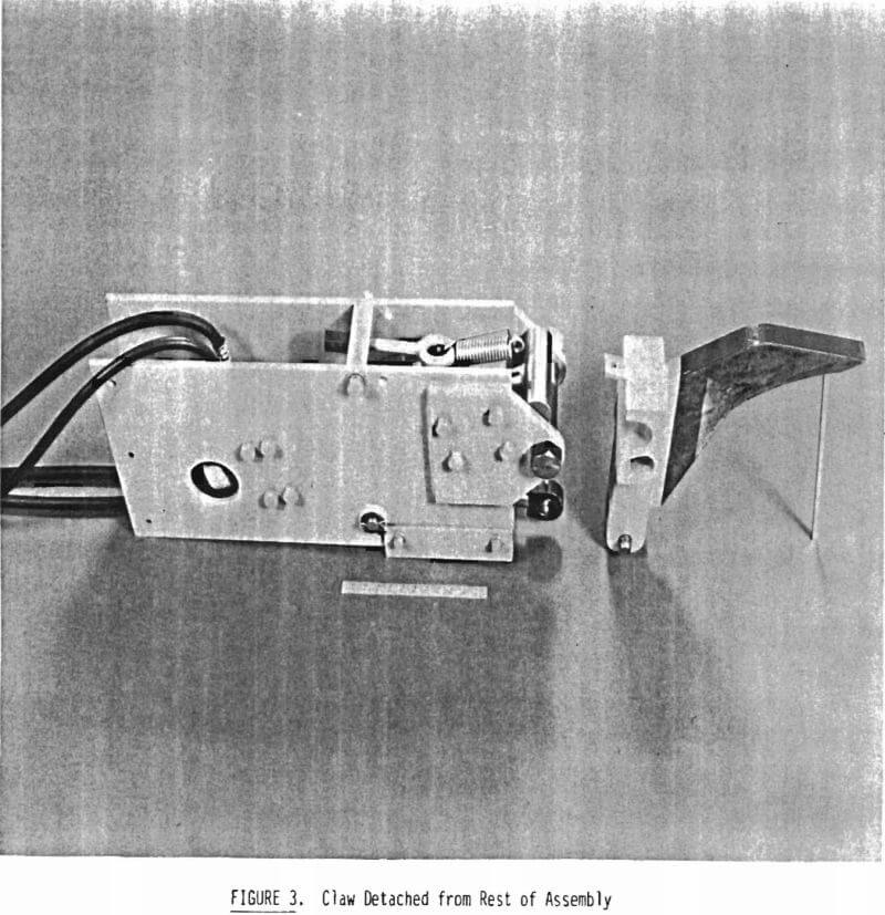
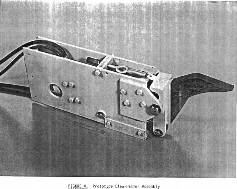
initial part of the rotation also unloads the T-tool to protect the hammer from excessive side loading. The claw is configured with a narrow tip and a curved shank so that the pivoting action causes a prying action between the claw and the rock, analogous to that achieved with a hand-scaling bar. The advantage of this arrangement is clear. The heavy prying loads are transmitted between the claw and the rock, and not to the rest of the claw hammer assembly and boom.
The top of the claw is spring-loaded, which helps maintain contact between the T-tool and the hammer. This not only improves stability during the hammering mode but also helps to lessen wear and, possibly, reduce breakage of the T-tool and claw by controlling unrestrained rebounding of these parts.
The T-tool delivers the hammer blows from the hydraulic hammer to the claw. Its shank is inserted into the hammer and retained the same way as a standard tool for this hammer. The cross-T of the tool fits into a mating recess in the claw to help resist overturning rotation of the claw when being side loaded. The cross-T also helps distribute the hammering loads over a larger surface area between the claw and itself.
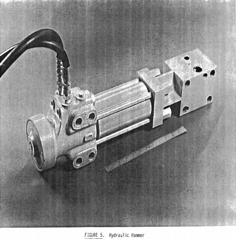
Although necessarily compact to meet the design need for a small scaler, the hydraulic hammer (Figure 5) has significant capacity for its size. The blow energy rating is 115 ft-lb. The hydraulic hammer impacts the T-tool, which, in turn, impacts the claw. The line of force coincides with the top of the claw, causing it to operate as a chisel. Thus, the vibrating claw can scale by itself in stable formations, or can augment the prying mode in less stable formations.
Testing Procedures and Results
The prototype claw-hammer was subjected to quality assurance bench tests and some preliminary field tests. Tests of actual scaling performance were outside the scope of this phase of the project.
Quality Assurance Testing
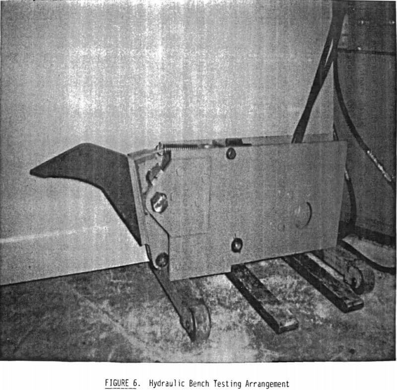
After fabrication, the claw-hammer assembly was tested on a hydraulic test bench (Figure 6) under the direction of the prototype’s fabricator, Advanced Industries, Inc., of Portland, Oregon. While the hammer was being run through its motions, a slight interference was found between the T-tool and its mating slot in the claw. This interference was then eliminated by reslanting the pivot slot to better match the claw’s rotational geometry. Re-bench testing verified that the interference had been eliminated. This design change is reflected in the as-built drawings.
Preliminary Field Testing
The finished prototype was then slated for testing on a Bureau crawler-tractor equipped with a backhoe boom. This required the design of a mounting bracket so that the claw-hammer assembly could be mounted in place of the backhoe bucket. Figure 7 shows the claw hammer mounted to the backhoe boom.
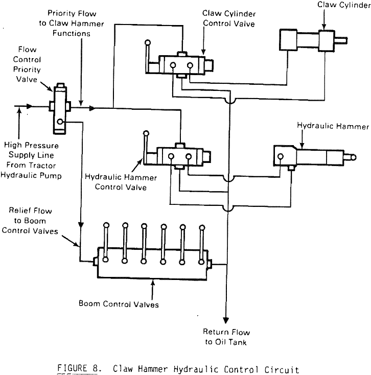
Hydraulic power for the claw hammer was obtained by tapping into the existing boom’s hydraulics. A flow control valve was added to prioritize the hydraulic supply flow to the boom and claw-hammer assembly. The two hydraulic control valves for the claw-hammer assembly received higher priority while the bypass flow was directed to the boom control valves. This temporary hydraulic modification was sufficient to allow limited testing of the claw hammer while maneuvering it with the boom. Figure 8 shows the hydraulic control circuit for the claw hammer assembly.
The claw hammer was tested for function of the individual hammering and prying modes against both concrete blocks and quartzite boulders. This
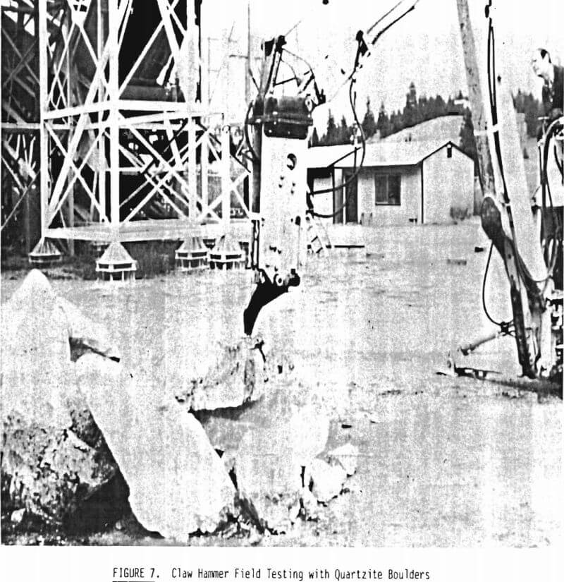
limited testing, exemplified in Figure 7, demonstrated the potential of the combination tool. The assembly was able to hammer the claw into solid rock and to pry off chunks that had been loosened by the hammering.
One major problem did arise during the early testing: the T-tool broke at the T-intersection. Subsequent investigation revealed breakage was design-caused. The original T-tool design called for an abrupt change in the cross-sectional geometry at the T-intersection. This change apparently led to a stress concentration problem. The problem was solved by redesigning the T-tool with generous fillets at the intersection to reduce the stress concentration factor. The redesigned T-tool did not break despite the considerable amount of testing performed after the problem was discovered.
Conclusions
Based on the limited testing performed, the combination claw-hammer tool concept appears viable. Early testing verifies that the functions of both a ripper scaler and a hammer-powered scaler can be successfully combined. Further testing in actual scaling conditions will be necessary to fully assess the device’s capability.
The prototype appears to be easy to maintain. The design was purposely kept simple and robust to make the device acceptable in the mining environment. It can be lubricated without any disassembly. The two primary wear items, the claw and the T-tool, can be replaced quickly and with a minimum of tools. If the need arises, the entire unit can be disassembled in approximately 15 minutes using common hand tools. In fact, the tool’s simplicity and ease of maintenance should help promote its potential for underground usage.
Recommendations
Battelle recommends that the prototype claw-hammer assembly be fully tested in a mining environment, preferably mounted on a fully articulated boom. Factors needing assessment include 1) operator acceptance, 2) visibility, 3) reliability, 4) maintainability, and 5) most important, overall scaling capability in various rock formations requiring both scaling functions. The assembly’s performance with respect to these factors then should be compared to that of other scaling methods to permit an assessment of the claw-hammer’s ultimate usefulness.
