Table of Contents
- Acid Washing
- Preheat Stage
- Elution stage
- Sequence Controllers
- Description of the Carbon Stripping Process (See fig. 1)
- Reagent Addition and Preheat
- Elution and Carbon Cool
- Transfer of Barren Carbon to the Regeneration Kiln Hopper
- Operation of the Carbon Stripping System
- Fault Finding Procedure for the Carbon Stripping System
- OPERATION OF THE Carbon STRIPPING SYSTEM (Step by Step Procedure)
- Transfer of Barren Carbon to Regeneration Kiln Hopper
- Optimization of Reagent Usage in a Carbon Stripping System
- Ok Tedi Plant Description
- Carbon Feed Using the “BOYLE” Pump
The Anglo American Research Laboratories AARL carbon stripping system used in this EXAMPLE has two definite advantages when compared with its most common counterpart, the Zadra system. It is much less expensive to operate and it produces a cleaner stripped carbon. It is however very reliant upon the availability of an abundant supply of good quality water and its water usage is far greater than that of either the Zadra system or the more recently developed solvent stripping system.
The stripping of gold from loaded carbon here involves two basic steps; Acid Washing and Elution. The elution step may be further divided into two major stages; carbon preheat and elution proper.
Here a separate column is provided for acid washing. The advantages of this are dubious in that there would be more than enough time in a twenty four hour period for both steps to be completed in one column. In any case the potable water system here does not cater for the running of both steps at the same time. Much greater benefit would have been derived from the provision of an additional eluate tank as it is in the later electrowinning stage that most of the present hold ups occur.
Acid Washing
This involves the soaking of the loaded carbon in a 3% HCL solution in order to remove impurities such as calcium,
copper and magnesium which can impede both the elution step and the later adsorption of gold onto the carbon after it has been returned to the CIP circuit. Acid washing of carbon is in fact used as a temporary substitute for thermal reactivation of carbon in some plants.
Preheat Stage
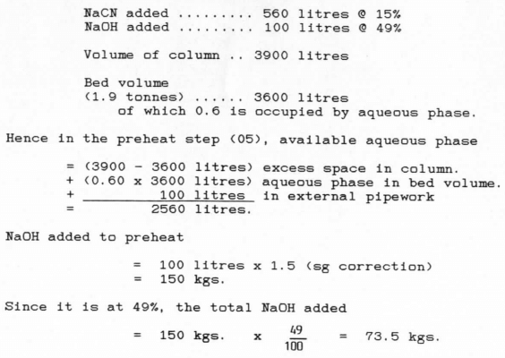
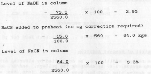
During this stage a 2% caustic/3% cyanide solution mixture is re-circulated through the loaded carbon in the elution column until such time as a predetermined “top of column” temperature is reached. By this time most of the gold and silver on the carbon will have been desorbed into solution and both the carbon and the solution will have reached an optimum temperature for the subsequent elution proper.
Elution stage
During this stage the gold and silver desorbed off the carbon during the ‘preheat .* is washed out of the column into the eluate tank. This stage takes 2 1/2 hours and involves the use of 5 bed volumes of potable water (21.6 cubic metres). The critical factor during this stage is temperature. It has been found that the optimum “top of column’ temperature is around 110 Deg C.
Sequence Controllers
The gold room uses the Anglo-American Research Laboratories stripping system to strip gold from loaded carbon in batches of approximately 1.9 tonnes. The process is fully automated and controlled by electronic sequence controllers which switch both pumps and valves for each step.
The controllers can be over-ridden to stop or reset a cycle or to start again, at any point. It should be remembered that no feedback to the controllers is provided and hence a signal for a pump to run or a valve to open does not necessarily mean that the item is operating. This can be confirmed by visual inspection at the pump or valve. Likewise it should be remembered that the controllers will not operate if a local stop switch is depressed. (See fig. 2)
Although the sequence controllers govern the various stripping stages it is essential to monitor the plant on a regular basis so as to ensure that all equipment is operating properly and that desired temperatures are being reached and maintained within the time limitations set on the controllers.
Description of the Carbon
Stripping Process (See fig. 1)
Acid Wash of Carbon
Carbon is loaded into the acid wash column from the loaded carbon surge hopper by opening the main inlet valve AV 401. Excess water and air are bled off through a screen and valve AV 414 to either the leach area sump or the tailings hopper. After filling, the main valve AV 401 is closed and dilute hydrochloric acid is injected into the bottom of the column via valve AV 403. Displaced water flows out of the top of the column through valve AV 414 to the tailings hopper. After acid injection and soaking, water is pumped into the bottom of the column via valve AV 404 and as it rises through the column to exit via valve AV 414, it rinses out the acid.
Transfer to Elution Column
After rinsing the carbon is pressure transferred to the elution column. Water is injected into the acid wash column via valve AV 404 to maintain pressure within the column and force the loaded carbon out through valve AV 406 into the carbon transfer line. Additional water is forced into this line via valve AV 402 and the carbon is forced along the line through valve AV 422 into the elution column. Displaced water flows out of that column through the inline filter, via valve AV 415 into the potable water tank.
Reagent Addition and Preheat
The start of the stripping cycle involves the addition of NaCN <2 to 3%) and NaOH (2%) to the column via valve AV 410. Displaced water flows out of the top of the column through the inline filter, along the pregnant solution line to the heat exchanger to exit via valve AV 416 into the eluate tank.
After reagent addition, valve AV 416 closes and the elution water pump recirculates the solution in the column by pumping it via the heat exchanger and valve AV 409 up through the column and out through valve AV 460 back to the water pump. Heat is transferred to this solution as it passes through the heat exchanger from thermocal which is being recirculated through a heater and the heat exchanger. The preheat stage continues for a preset time, at the end of which the desired “top of the column* temperature should be attained. By this time most of the gold will have been liberated from the carbon back into solution form. The thermocal heater and pump continue to operate throughout the preheat and subsequent elution stage so as to maintain desired operating temperatures.
Elution and Carbon Cool
During the elution cycle, water is drawn from the potable water tank and pumped through the heat exchanger via valve AV 409 into the column. The water then flows up through the column, taking with it gold that has been freed into solution during the preheat stage. This pregnant solution then flows out of the column through the inline filter and the heat exchanger, then via valve AV 416 to the eluate tank. This stage continues until five bed volumes of water have passed through the column (2.5 hours) after which desired barren carbon assays of -30g Au/tonne should be achieved.
At the end of the elution stage the thermocal heater stops and an additional amount of NaOH is pumped into the eluate tank via valve AV 420, this bringing the pH of the eluate solution up to the desired level. Potable water then continues to flow through the system as per the elution stage for another twenty minutes, this taking some of the heat out of the carbon and the thermocal. The thermocal pump operates for another two hours after the end of the carbon cool stage, this aiding the cooling down of the heater.
Transfer of Barren Carbon to the Regeneration Kiln Hopper
At the end of the carbon cool stage, water is pumped into the column via valve AV 409 so as to maintain pressure within it and force the barren carbon out of the column via valve AV 421 into the carbon transfer line. Additional water is injected into this line via valve AV 412 and the carbon is carried long the line to the dewatering screen above the regeneration kiln feed hopper.
Electrowinning
One bed volume (thirty minutes) into the elution stage the eluate pump is started and pregnant solution from the eluate tank, is pumped up into the electrowinning cell on the first floor of the goldroom. It then flows back into the eluate tank. As the solution flows through the electrowinning cell, gold is plated on to the steel wool cathodes. This recirculation process continues for around 14 to 16 hours after which period of time there should be no more than ~1 g Au/tonne of eluate remaining in solution. The barren solution is then pumped out of the eluate tank into the process water tank.
Operation of the Carbon Stripping System
Details of the step by step sequence controller operation for the entire stripping process are outlined in part 2. This information is displayed on the control cubicle. The mere following of the instructions given in that section will not ensure effective stripping results as there are many extraneous factors which need to be taken into account. Part 3 outlines in full detail every action required on the part of goldroom personnel in order to operate the plant successfully. Operators unfamiliar with The Granites stripping system should follow Part 3 directly. Loose copies are available. “Operation of the Stripping System – Step by Step Procedure”.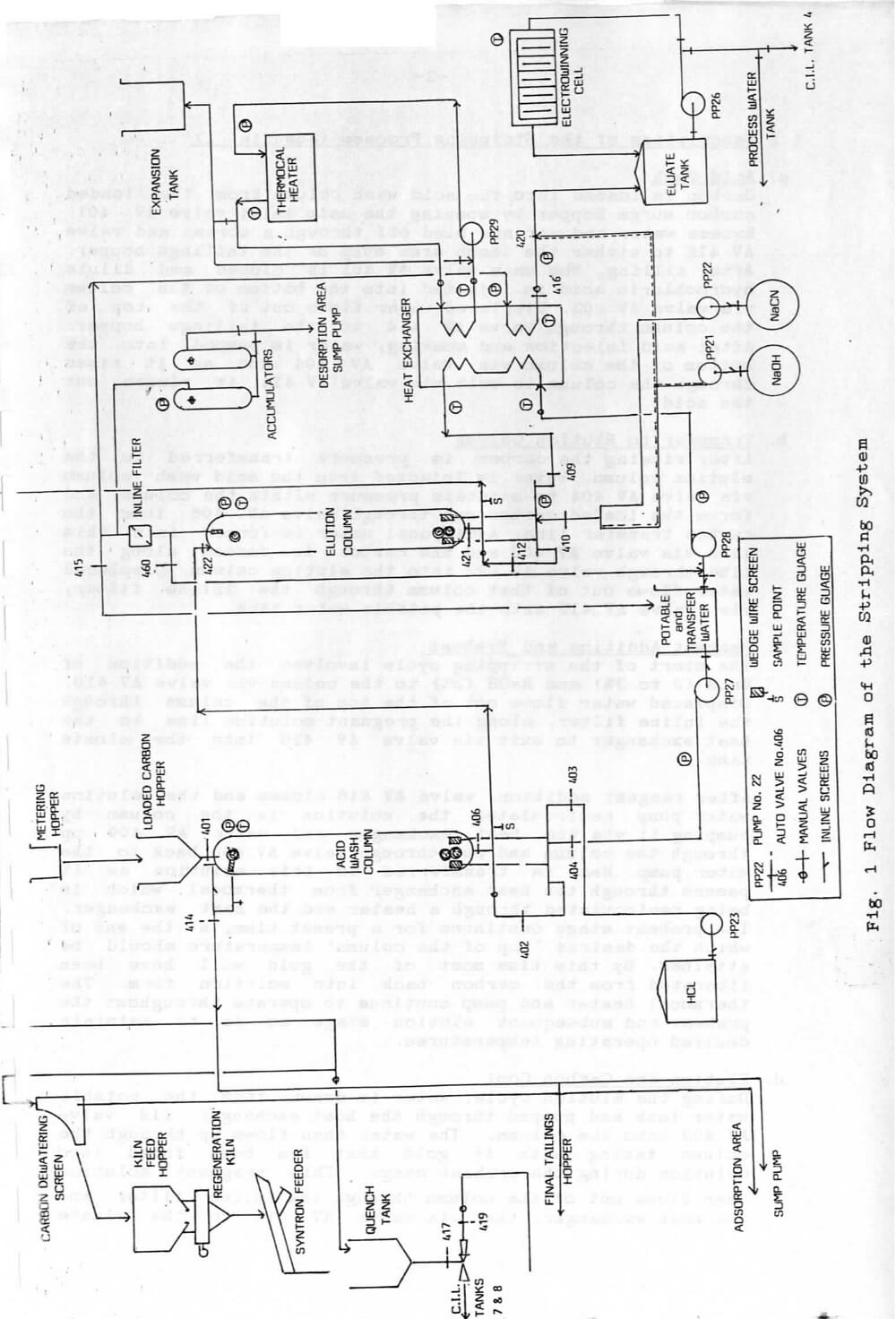
Fault Finding Procedure for the Carbon Stripping System
Should any difficulties occur during the stripping process, possible faults with remedial action have been detailed in part 4 of this manual.
- STEP
Step display - INSTRUCTION
Instruction display. The STEP display indicates the step number (or process) in progress, and the INSTRUCTION display consisting of OP, DATA-1 and DATA-2 displays indicates the step advance conditions. These displays are used for monitoring the keyboard programming, as well as monitoring the program being executed. - RUN
Run display (LED) The LED indicator lights when the START switch is depressed in the manual or automatic mode and goes off when the STOP switch is depressed. - INPUT
Input display (LED) For indication of input status. - OUT
Output operation display (LED) The LED indicator lights when the output is not prohibited. - OUTPUT
Output display (LED) For indication of output status. The LED indicator also illuminates when the OUT ON/OUT OFF selector switch is set in the ’’OUT OFF” position. - FLAG
Flag display (LED) For indication of flag status. The LED indicator also illuminates when the OUT ON/OUT OFF selector switch is set in the ’’OUT OFF” position. - Operation switches:
AUTO/M/E
AUTO selector switch
AUTO
Automatic operation mode selection.
M
Manual operation mode selection
E.AUTO
Automatic or manual mode selection by external signal.
OUT ON/OUT OFF selector switch
In the OUT OFF position, outputs (including flag outputs) are prohibited. The OUT ON position allows outputs to be generated.
RESET switch
Depressing this switch causes the program to reset to step 01 and places the controller in STOP state.
START switch
Depressing this switch places the controller in RUN state, causing automatic or manual operation to start.
STOP switch
Depressing this switch places the controller in STOP state causing the current step to be held. - Program Console
Keyboard switches for programming. Program console switch must be turned on when programming. - Battery Lid
Battery, unit number setting switch for parallel processing and program protect switch are mounted inside. - Unit Number Setting Switch.
Acid Wash and Rinse Steps
- Press SEQUENCE START. “Run” and “Output” lights show. Manually initiate sequence by switching the Carbon Fill Selector switch to “Fill” and then “Complete” after the column has filled with carbon. REFER STEP 01
- Press ACID WASH RINSE START. This adds concentrated HCL and water to the column. REFER STEP 03
- Allows soak in acid.REFER STEP 04
- Rinses carbon column with water to remove acid and restore neutral pH to the solution. REFER STEP 05
- On completion of the water rinse step, the alarm will sound. Press ALARM ACCEPT.
- Press WASHED CARBON TRANSFER START to commence the transfer of carbon to the elution column. REFER STEP 10
- On completion of transfer the alarm will sound. Press ALARM ACCEPT and then shut down by pressing WASHED CARBON TRANSFER STOP
Sequence is ended.
Note:
- During the carbon transfer take LOADED CARBON samples from the sample point on the transfer line.
- Complete log sheet by recording times and volumes of water used during this sequence.
- The programme can be interrupted at any stage by pressing SEQUENCE STOP. It can be resumed by pressing SEQUENCE START. The cycle will then start again from the point at which it was interrupted.
Stripping sequence steps
- Press SEQUENCE STAPT. The “Run” and ’’Output” lights will show on the panel. REFER STEP 01
- Press STRIPPING CYCLE STAPT. Cyanide and caustic are added to the elution column to soak the bed of carbon. REFER STEP 02
In this cycle the strong cyanide and caustic solution is circulated. The temperature is raised from ambient to 90°C. REFER STEP 05
The stripping stage is done by continuously pumping water at about 110 Deg C through the bed of carbon in the elution column. The pregnant solution or eluate, flows into the eluate tank. REFER STEP 06
An addition of caustic is made to the eluate. REFER STEP 07
The cool rinse stage. The burner shuts off (The thermocal pump will continue to run for two hours) and cool water is pumped through the elution column. REFER STEP 09 - On completion of the stripping cycle, the alarm will sound. Press ALARM ACCEPT.
- Press STRIPPED CARBON TRANSFER START to commence transfer of carbon to the regeneration kiln feed hopper. REFER STEP 13
- The alarm will sound at the end of the designated transfer time. Press ALARM ACCEPT. The transfer pump will still be operating. If all of the carbon has been transferred (check sight glass) stop by pressing STRIPPED CARBON TRANSFER STOP.
Sequence is ended.
Note
- During the carbon transfer take STRIPPED CARBON samples from the sample point on the transfer line.
- The electrowinning cell may be started after one bed volume has passed through the column in step 6.
- Fill in the relevant information on the log sheet.
- To stop programme at any stage press SEQUENCE STOP
Resume programme by pressing SEQUENCE START
OPERATION OF THE Carbon STRIPPING SYSTEM (Step by Step Procedure)
- Check the electrowinning cell and take a sample over to the laboratory. Label the sample:
**E/V No. _ DATE TIME TAIL”
- Check the potable water meter reading and the available potable water (off tank level indicator); and the gas pressure. Note these on the log sheet for the preceding day.
Acid Wash
- After ensuring that there is sufficient carbon in the loaded carbon surge hopper, switch the valve control switch (See fig. 3) to ‘‘auto’ to open the valve.
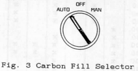
Then put a running hose in the hopper and wait for the acid wash column to fill with carbon. When the carbon is visible in the top sight glass switch the control switch back to ‘manual* to close the valve. Check to ensure that the inline trash screen is clear.
- Make sure that the manual valve on the acid container is open. Record the time, the level of acid in the container and the reading for potable water off the meter by the potable water tank, on the goldroom log sheet. Press the ‘acid wash/rinse start’ button on the main control panel.
- Check to see that the acid pump is running. As soon as it stops check and note on the log sheet, the acid level in the container. Also close the manual valve on the container.
- The sequence controller will automatically take the sequence through the soak step (04) and the rinse step (05). At the end of step 5 the alarm will sound. Check the pH level of the solution from the sample point at the top of the column. If it is over 5 press the ‘alarm accept’ button.
Washed Carbon Transfer
- Press the ‘washed carbon transfer start* button on the control panel. Whilst the carbon is being transferred take samples from the transfer line sample point, every five minutes. Rinse the combined sample and label it:
”STRIP No. ____ DATE LOADED Au content”
- Towards the end of the carbon transfer step the alarm will sound. Press the ‘alarm accept’ button but do Not press the ‘washed carbon transfer stop* button until the acid wash column is seen to be empty by way of both the bottom of column sight glass and the absence of carbon in the transfer water at the sample point.
- After the transfer is completed and you have pressed the ‘washed—-carbon transfer stop’ button, drain out the accumulator vessels by way of the two ball valves near the right hand side vessel and then clean out the filter bag at the top of the elution column. Make sure that the filter bag has no holes in it and that the pliable band fits snugly into the ledge inside the filter housing. Also ensure that the steel ball has been put back inside the bag.
- Close the accumulator drain valves and also the manual back up valve on the barren carbon transfer line.
Reagent Addition and Preheat
- On the log sheet, note the meter readings for the caustic, and cyanide pumps and also that of the potable water supply.
- On the elution control panel press the ‘sequence start* button and then the ‘stripping cycle start* button. This step will not commence if the eluate tank ‘low level* light is not on, i.e. the tank has not been pumped out or the low level indicator is faulty.
- During the addition of reagents step (02) visually check that the pumps are operating and also record the meter readings immediately after the pumps stop. Should the output of either pump be drastically short of the desired amount (Presently 565 litres of cyanide and 100 litres of caustic) immediately press one of the pump stop switches and then reset it, This action will prevent the sequence controller from continuing on through the elution programme. It will then be necessary to add additional reagent by the steps outlined below:(i) Switch the controller to “manual* by way of the black selector switch on the main control panel.(ii) Open auto valves AV 410 and AV 416 manually.(iii) Start the desired reagent pump locally and run it until the desired additional litres have been added as per meter.(iv) Reset the pump stop switch.
- Close auto valves AV 410 and AV 416 manually.
- Switch the controller back to “auto*.
- Press the “sequence start* button on the control panel. The controller will automatically continue on with the preheat cycle (step 05) .
- Check to ensure that the thermocal heater is operating. If it fails to start it is most likely to be because the thermocal pressure is too low as a^result of an airlock in the heater circuit. Correct this by opening the ball valve above the “thermocal in* line for thirty seconds or so. If some time has elapsed before it was noticed that the heater was not going, the preheat step (05) should be restarted by the following method:-(i) On the sequence control panel, switch the left hand side toggle switch from “auto* to “m* and the adjacent toggle switch from “out’ to “out off’(ii) Press the white “reset* button next to the toggle switches.(iii) By pressing the blue “start* button step the controller through to step 05 again.
- Put the toggle switches back to “auto* and “out on* respectively. The preheat step will then automatically commence again and run for the full set time.
- Monitor the preheat step regularly and record both temperatures and pressures on the log sheet every half hour, the desired top of column temperature at the end of the preheat step varies with weather conditions, but during the cooler months it should reach QO0 approximately. If this temperature is not reached then the preheat step will need to be extended by switching the left hand side toggle switch to “m* . The preheat step will then over-ride the timer and continue on until the toggle switch is put back to auto.
- Should the column pressure rise rapidly during preheat to above 400 kPa, it may be necessary to stop the cycle. Either stop the elution pump locally or press the red ‘sequence stop’ button on the control panel. Then drain the accumulator vessels until the top of column pressure falls below 150 kPa. Restart by resetting the pump stop switch and pressing the ‘sequence start’ button on the control panel.
Elution
- After preheat the controller will automatically go into the elution step (06). Monitor this step regularly and record temperatures and pressures every thirty minutes.
- Start the electrowinning cell after the first bed volume -thirty minutes running time.
- After one hour in the elution step (06) the following operating parameters are considered desirable.
Top of column temperature ……… around 110°C
Top of column temperature ………. pressure around 130 kPa
Bottom of column temperature …… around 125°C
Bottom of column pressure ……… around 300 kPa
Elution water pump pressure ……. 270 to 300 kPa
Heat exchanger pressure in …….. 170 to 190 kPa
Heat exchanger pressure out ……. 150 to 170 kPa
Thermocal temperature in ………. around 125<=,C
Thermocal temperature out ……… around 122<=,C
A falling top of column temperature is the best indicator of possible trouble caused by such things as dirty heat exchanger plates, thermocal heater not operating properly or pegged inline screens.
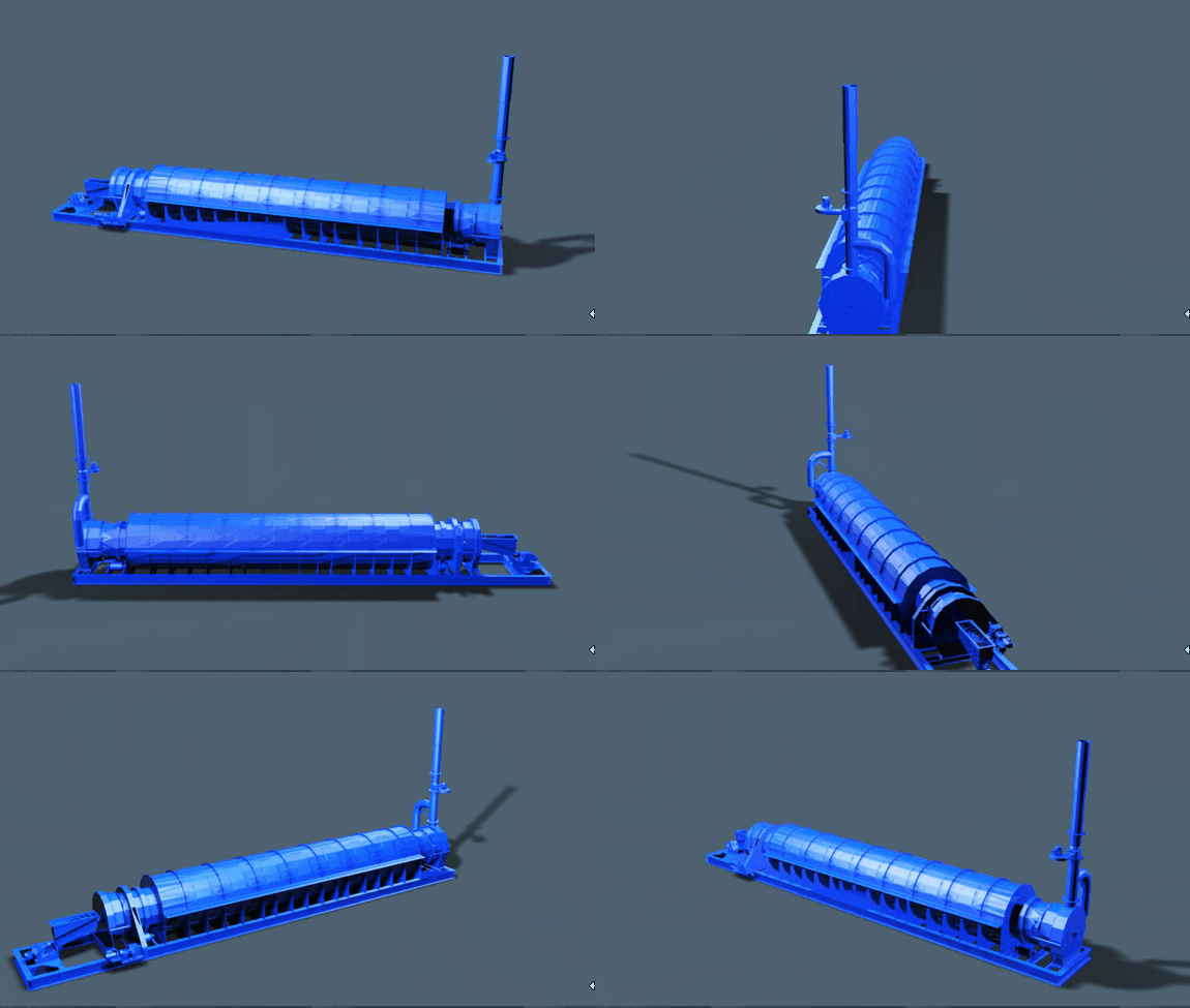
Transfer of Barren Carbon to Regeneration Kiln Hopper
- Open the back up manual valve on the barren carbon transfer line.
- Back flush the carbon transfer line into the quench tank by attaching a hose to the minsup coupling behind the dewatering screen above the feed hopper. This step is only necessary if the previous lot of barren carbon was transferred directly into the quench tank.
- Close the carbon delivery valve above the quench tank.
- Make sure that the dewatering screen is clean.
- Fill the carbon transfer line by putting a hose on the sample point and running it until an adequate flow of return water is evident. Do not over flush as this could flood the kiln.
- Press the “stripped carbon transfer start* button and throughout the transfer monitor:(i) The flow of return water. Should this decrease markedly, stop the elution water pump locally and flush the carbon transfer line again. Restart the transfer by pressing the “sequence start’ button.(ii) The bottom of column pressure. Should this rise suddenly above 220 kPa, immediately stop the elution water pump and repeat the procedure outlined in (i) above.
- Take regular samples throughout the transfer and label the combined sample:
’’STRIP No. _ BARREN, DATE _, activity and Au”
- The alarm will sound at the end of the programmed transfer time. Press the “alarm accept’ button and then check to see if the transfer is completed by:-(i) Looking in the bottom sight glass.(ii) Observing clear water only gushing from the sample point.(iii) Noting a marked increase in the flow of return water. Wait for this before stopping the transfer by stopping the elution water pump locally. This is important as the increased flow indicates that the carbon transfer line is flushed clear. Again do not risk flooding the kiln by over flushing the line.
- After stopping the elution water pump locally, reset the switch and then reset the sequence controller by:(i) On the sequence controller pane 1, switch the L.H.S. toggle switch to “m’ and the adjacent toggle switch to “out off’.(ii) Pressing the white “reset’ button next to the toggle switches.(iii) Pressing the blue “start’ button and then putting the toggle switches back to their original positions.
Electrowinning
One bed volume (thirty minutes) after the commencement of the elution step (06) the electrowinning cell may be put into operation. When a strip is not in progress and the cell is required to electrowin intensive cyanidation product, at least 15 cubic metres of hot water should be pumped from the column into the eluate tank beforehand.
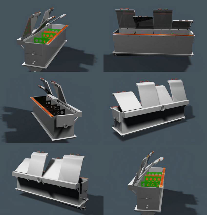
Start Up Procedure
- Check the valves by the eluate tank.
- Shut the drainage valve at the base of the cell.
- Open the input valve partly.
- Make sure that the fume exhaust fan is operating. This should be left on at all times.
- Start the pump – it will not start if the local switch outside the goldroom door has been left isolated.
- Open fully the input valve.
- When there is a flow over the weir at the discharge end of the cell, switch on the rectifier and adjust the volts to no more than 5.0; the amps will be around 600.
- Regulate the input valve so that the eluate level is about half way up the overflow outlet of the cell.
- Monitor the cell regularly to check on both eluate level and volts.
- Check the pH and cyanide levels. They should be around 12.5 and approximately 0.3% respectively.
- Tell the night shift personnel that the cell is operating. If there is a power failure, the pump will need to be restarted at the local switch.
Shut Down Procedure
- Take an eluate sample. The assay should be <5 ppm./Au before shutdown and if there is time, <1 ppm./Au.
- Stop the pump – reset the switch immediately.
- Open the dump valve on the line leading to the eluate tank.
- When the cell is half empty, switch off the rectifier and turn the control knob back to zero.
- Shut or open the appropriate valves by the eluate tank.
- Before pumping out the spent eluate to the process water tank, advise both the intensive cyanidation operator and the shift foreman.
- When the tank is pumped out, the eluate pump should stop and the low level indicator will come on on the control panel. Change the valves by the eluate tank back to the positions required for electrowinning.
Points to Watch
- High eluate level in the cell could indicate:
(i) The cathodes are blocked with slime or fully loaded.
(ii) The input valve is opened too far. - Low eluate level in the cell could indicate:
(i) The pump is faulty.
(ii) The input valve is shut too far. - Incorrect voltage level could indicate:
(i) Too much resistance in the cathodes, i.e. they are heavily loaded or slimed up.
(ii) Faulty electrical contact on the cell.
(iii) Incorrect pH level. - Eluate is poisonous – wear gloves when taking a sample or handling the cathodes. Do not linger by the cell even when the fume exhaust fan is operating.
Optimization of Reagent Usage in a Carbon Stripping System
Desired Reagent Levels
Acid Wash
Step 03 ………………. 2% HCL
Stripping sequence
Step 02 ……………2 to 3% NaCN
Electrowin ….sufficient NaOH for pH 12.5
Control of Reagent Addition
The reagent addition can be controlled by altering either the pump speeds, i.e. by changing the pulleys, and/or adjusting the dosing time that has been programmed into the sequence controller. Altering of the pump speed is preferable in cases where a change in the level of one reagent only is desired on a permanent basis. Changing of the dosing time in the stripping sequence (step 02) results in the changing of the levels of both NaCN and NaOH as the same timer controls both pumps. Should it be necessary for some reason to add an additional amount of either reagent at the end of step 02, e.g. is cases where the pressure relief valve of a particular pump is faulty and reagent goes back into the tank, this may be done by operating both the particular pump and the relevant valves manually.
Example Calculation of Reagents Required for Stripping
Sequence Step 02
Determining Optimum Acid Wash Rinsing Time
The acid rinse step (05) is currently set for 2.5 hours. This could be excessive and wasting potable water. To determine the optimum time it is necessary to take samples every fifteen minutes from the rinse discharge line sampling point at the top of the acid wash column.
These samples should be analysed for Ca plus Mg and then the totals plotted versus time. When the curve flattens out, the rinsing is sufficient (even if the pH is only 4). The sequence controller time for step 06 should then be reset to the time indicated by the graph.
Mechanism of Catalyst Deactivation
https://archive.org/details/GoldMine1987004
Ok Tedi Plant Description
The Ok Tedi plant had a nominal design throughput of 24 tonnes of carbon per day. The design provided for two 24 tonne per day columns to give 100% standby capacity.
Being the first commercial continuous elution column built by Bechtel it was very conservatively sized. Each column was 1500mm diameter by 10 metres high which for 24 tonnes per day of carbon per column was equivalent to the pilot plant operating at 1 tonne per day.
Based on the Pilot plant test results these columns would each have an eluting capacity of 60 tonnes of carbon per day. In practice the feed system to each column had a limit of 36 tonnes per day.
The Ok Tedi plant (see Figure 2) differed from the pilot plant in a number of significant ways, the main one being the carbon feed system which comprised two sets of transfer tanks and vessels which were alternately filled with carbon and the vessels pressurised with hot final eluate to drive the carbon into the column. This system conserved heat and allowed the top of the column to operate at up to 135 °C compared with the pilot plants 103 °C.
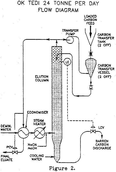
The other significant change was the injection of NaCN and NaOH into hot demineralized water to form barren eluate just prior to entry to the column. This had two advantages, firstly it allowed fast on line adjustment of the composition of the barren eluate based on free NaCN in the final eluate, and secondly it minimised the problem of fouling of the barren eluate heater.
The following calculated results were obtained from the computer simulation of the elution column using Ok Tedi plant design data.
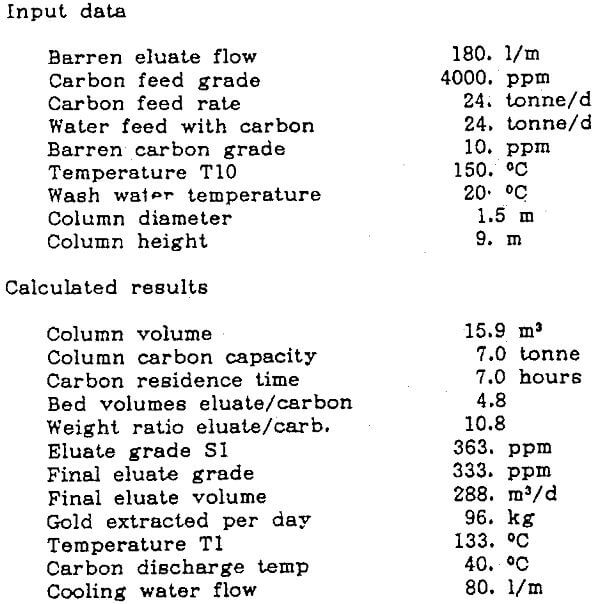
Measured results
The Ok Tedi plant was seldom operated under the design conditions listed above. During commissioning the above figures of eluate volume and temperature were achieved, loaded carbon grades were lower at that time so the final eluate was of corresponding lower grade. The vessel was oversized and hence reducing eluate flow was not recommended to increase final eluate grade because of the possibility of channelling. The cooling water flow started off at nearer 160 l/m with new carbon, however as the carbon degraded the cooling water flow decreased to nearer the calculated figure.
Over the past year the gold extracted has averaged approximately 60 kg per day on a 365 day per year basis. Carbon feed grades have varied between 4700 and 900 ppm with corresponding final eluate as high as 500ppm gold but averaging nearer 200 ppm. Carbon feed rate has varied up to 35 tonnes/day, with an average of approximately 24 tonnes/day.
The startup and operation at Ok Tedi are discussed in some detail in the Reference A.M. Stone, D.C. McDonald (1988)
Carbon Feed Using the “BOYLE” Pump
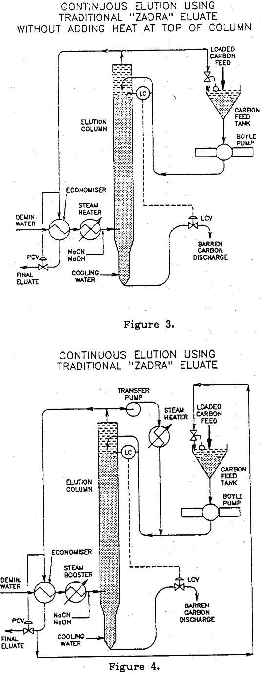
The “Boyle” pump ref. B.A. Boyle (1983) is a full bore positive displacement slurry pump. Preliminary tests with this pump have proved that it will pump granulated carbon at settled density over short distances. This pump would replace the transfer vessels in the Ok Tedi design and could be located near the top of the column using the configuration shown in Figure 3 or near the bottom of the column if used with a eluate transfer pump as shown in Figure 4.
The use of this type of pump should make the continuous elution process competitive in smaller sized plants, possibly down to one tonne per day plants or smaller.
A one tonne per day column would be approximately 300 mm diameter by 5 metres tall.
The circuit shown in Figure 4 has the following advantages over that shown in Figure 3 and may become the preferred process.
- The carbon pump can be placed near grade, thus reducing structure requirements.
- The carbon pump operates at ambient temperatures thus eliminating the requirement for a high temperature design.
- Heat is applied to the transfer pump circuit so that the top of the column is hottest thus promoting better elution.
- The carbon discharge valve may be controlled from the pressure drop along the carbon feed line thus eliminating the requirement for a switch to detect carbon level in the column.
Continuous Elution Using Preconditioning Solution and Hot Water Eluate
An arrangement for making the process described by Zadra (1952) continuous in which “20 grams of carbon are first preconditioned in 200 ml of 2% NaCN and 0.5% NaOH solution for 30 minutes at boiling point and then eluted with 200 ml of boiling water 19” times is shown in Figure 5.
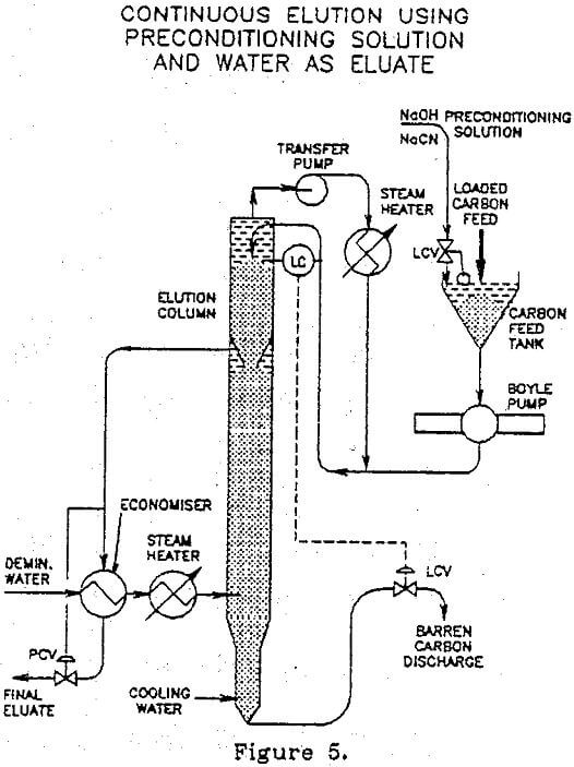
Based on Zadra’s work this process has the potential to use less reagents than the traditional “Zadra” process.
In this case a two compartment column is used. Loaded carbon in cold preconditioning solution is transferred to the top of the column via the Boyle pump and hot (150°C) preconditioning solution pumped from the top of the column via the transfer pump and steam heater. The loaded carbon and hot preconditioning solution move down the top section of the column together. As the carbon and preconditioning solution move into the lower section of the column the hot water eluate passing up the column elutes the gold from the carbon and flushes out the preconditioning solution to become the final eluate. The final eluate exits just below the top compartment as shown in Figure 5.
