Table of Contents
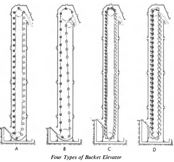
Bucket elevators are used for the elevation of dry or pulped ore. They consist of an endless chain or belt carrying the buckets vertically or at a steep angle. On reaching the top pulley they should turn at sufficient speed to fling their contents out with a measure of centrifugal force. The feed is directed into a gathering boot or to buckets rising from a boot. Wet ore can be drained through perforations in the buckets. A rod can be so suspended as to rap the discharging bucket and so help to shake out packing sludge.
Belt bucket elevators are by far the most common appliance for elevating ore, whether wet or dry. For wet work, they have the advantage over chain-bucket elevators of requiring no difficult and expensive lubrication and of having fewer wearing and friction-producing surfaces. The capacity of a given belt, however, is limited by its adhesion to the head pulley; this can be augmented by a wrapping of less slippery material around the pulley. As compared with inclined conveyors, they occupy much less floor space, and can also elevate thin pulps. It is important to provide means for emptying the boot of an elevator when repairs are needed; so placed that the discharged material can be sluiced or easily transferred by other means to an adjoining elevator.
Scraper elevators work by means of flights or rakes attached to a moving endless belt. The material is trapped against the underside of the housing and dragged up to the discharge point.
Bucket Elevator Conveyor
A Bucket Elevator Conveyor compared to classic belt conveyors which can handle the bulk of the dry ore moved through the modern plant, have a system including a tripper. The belt conveyor obviously includes the belt, the carrying and return idlers (B and E), the take-up (F), the tripper and shuttle belts if used, the drive (C), the belt cleaner (near D).
The standard “rubber” belt has a cotton foundation which must be strong enough to withstand the driving pull and the loading strains. The “weight” of duck in ounces, refers to a single thickness or “ply” 36″ x 42″. Plies are bonded together with rubber, and the pull needed to separate two plies in a strip one inch thick is termed the “friction”. It is between 12 lb. and 24 lb. and chosen for required duty and flexibility. The plies must not separate under the worst conditions (i.e. when rounding the end pulleys). This carcass (plies) is protected above and below by rubber, of the specified tensile strength (800-4000 PSI). Covers vary in thickness from 1/16″ to ½”. For severe service, a “breaker strip” of open mesh fabric may bind cover the carcass and confine any tear arising in use. Cord belts have additional longitudinal cords embedded in rubber.
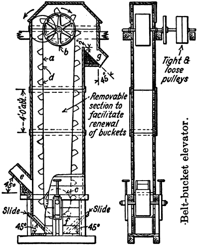
A bucket elevator consists of a number of buckets (d) fastened to an endless chain or belt (a) running respectively on two sprockets or pulleys (b, c) at different elevations. Material is fed at (e) directly into the buckets or is scooped up from the BOOT (f) and carried up and discharged into a receiving hopper (g) as the buckets pass over the upper (HEAD) wheel. The line joining the centers of the pulleys or sprockets may be inclined at any angle between 65 or 70° and the vertical. Bucket elevators are called continuous if the buckets are spaced practically touching and centrifugal discharge if the buckets are spaced say one or more bucket-depths apart. The height of lift in concentrating mills is seldom over 75 ft. but there is no definite limit in the ordinary range of requirements.
The drive is usually by a spur gear on the head shaft and pinion on a jackshaft belt-driven from a motor or line shaft. Direct belt drive from a line shaft to the head shaft is sometimes used; also direct connection of a motor to the pinion shaft. Gear drive is better than belt drive because it permits higher drive-belt speed and belt drive is better than direct connection because the belt will slip in case of a sudden jam and possibly save breakage of the bucket line.
The Head shaft should be extra heavy and as short as possible. The greatest stress is due to the weight of the loaded bucket line and to sudden shocks arising from obstruction to the free motion of the line; a shaft strong enough to support this loading is more than large enough to transmit the necessary power. A light shaft that bends under load causes uneven and excessive wear on bearings.
Size of the head shaft. Let w = total load in lb. of shaft, pulley, bucket line and ore; l = length in inches of the shaft between bearings; d = diameter of shaft in inches; z = section modulus = πd³/32; s = permissible working stress in lb. per sq. in. = say 5000 lb. Then wl/4 = sz = 5000 πd³/32 and d³ = wl/1963.5.
Bearings may be of the standard pattern but preferably ball-and-socket, grease lubricated. Special collars with an interlocking rim to cover the end of the bearing are sometimes used to exclude grit; closed ends aid exclusion. Shafting is frequently turned down on the ends to permit the use of smaller-sized bearings.
A rubber belt is a usual medium for carrying buckets in American concentrating-mill practice; balata belts have been widely used in South Africa. Rubber elevator belts are usually made with 32-oz. duck; for heavy work, 36- or 42-oz.; with a 1/32- to 1/8-in rubber cover on the pulley side for protection against pulley slip and some cover on the bucket side also, to provide for the wear of entering feed; for wet materials, the cover on the pulley side is usually twice as thick as on the bucket side and ranges up to 1/8-in. The edges usually have an extra-heavy covering. The belt should be two to four in. wider than the bucket to prevent the buckets from catching on the housing or any other projection. Elevator belts are subject to heavy loads; surface wear is severe both on account of loading conditions and slip and creep at the head pulley; the perforations for bolts allow access of grit and water, and this in conjunction with acute bending around small boot pulleys, and frequent bending due to short length disintegrates the internal bond (friction). (Creep is a change in belt length, due to difference in tension on the two sides of the head pulley, so that the belt shrinks in passing from the upside to the downside and this causes relative movement between the surface of the pulley and the belt).
Belt replacement is the most important item of upkeep in elevator operation so that precautions to extend belt life pay for themselves in short periods. On elevators with buckets spaced some distance apart and run at low speeds, triangular strips of wood are sometimes fastened to the belt between buckets to prevent material from running along the belt and getting caught behind the buckets; this practice is reported to have greatly increased the life belts.
Bucket Elevator Manufacturers
Here is a list of Bucket Elevator Manufacturers:
Chain Bucket Elevator
Chain bucket elevators, in spite of their multiplicity of wearing and breaking elements, can be used satisfactorily far dry work but must then be lubricated with heavy grease to minimize the effect of grit; their capacity is limited only by the size of buckets that, can be supported. Certain types have a pronounced advantage in being able to receive or discharge at a number of points in their travel, thus combining the functions of elevator and conveyor.
The advantage of a Chain Bucket Elevator over a conveyor belt is that it can lift material vertically and can handle large quantities of material. The special design of the buckets ensures high stability and reduced risk of spillage.
A Bucket Chain Elevator is designed to lift material from point A to point B by means of buckets. The buckets are pulled by two chains. The Chain Bucket Elevator is typically used to lift the reject material and return it to the main flow in a sampling solution.
- The Chain Bucket Elevator C is designed to lift the reject material and return it to the main flow in a C-like trajectory.
- The Bucket Chain Elevator Z is designed to lift the reject material and return it to the main flow in a Z-like trajectory.
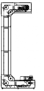
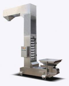
The Chain Bucket Elevator consists of an inlet hopper, a vibration feeder, buckets, a gear-motor drive, inspection hatches, and an outlet chute. There is an inlet hopper at the bottom with a VF that provides a consistent flow of the material into the buckets. The buckets are mounted on the chain that continuously pulls the buckets around by a geared motor. At the top of the unit, there is an outlet chute where the buckets are emptied. There is a drawer in the lower section allowing for easy cleaning. The chain is manually adjustable.
Industrial Bucket Elevators

|
 |
 |
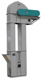 |
Bucket Elevator for Sale
For all or any of your bucket elevator needs, please contact us now. We do sell several types of elevator buckets.
Bucket Belt Elevator
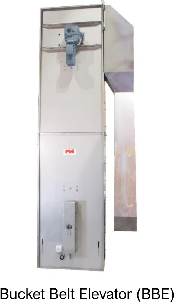
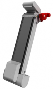
The Bucket Belt Elevator (BBE) is designed to lift material from point A to point B by means of buckets. The buckets are attached to a belt that pulls them around. The Belt Bucket Elevator is typically used to lift the reject material and return it to the main flow.
- Compared to a conveyor belt the Belt Bucket Elevator can lift material vertically.
- The Belt Bucket Elevator can handle large quantities of material.
- The special design of the buckets ensures high stability and reduced risk of spillage.
A Belt Bucket Elevator consists of an inlet hopper, a vibration feeder, buckets, a gear-motor drive, inspection hatches and an outlet chute.
There is an inlet hopper at the bottom with a VF that provide a consistent flow of the material into the buckets. The buckets are mounted on the belt that continuously pulls the buckets around by a geared motor. At the top of the unit there is an outlet chute where the buckets are emptied. There is a drawer in the lower section allowing for easy cleaning. The belt is manually adjustable.
Our sampling equipment and sampling systems operate in accordance with approved international material standards such as ISO, ASME, GOST, EN as well as DS3077 (2013). 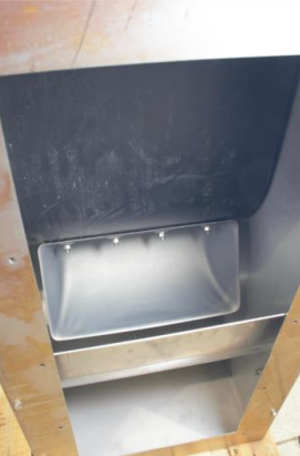
All sampling equipment and solutions aim for compliance with the principles laid down in the Theory of Sampling (TOS) and gives our customers reliable knowledge of the material properties such as moisture content, particle size distribution, mineral proportions, and content grade essential for commercial, operational, and technical characterization.
Options:
- The Bucket Belt Elevator C (BBE-C) is designed to lift the reject material and return it to the main flow in a C-like trajectory.
- The Bucket Belt Elevator Z (BBE-Z) is designed to lift the reject material and return it to the main flow in a Z-like trajectory.
- For ATEX zone environment, the Belt Bucket Elevator can be equipped with Explosion Panels in the vertical as well as the horizontal section of the Belt Bucket Elevator.
- The buckets can be supplied with coating reducing stickiness of material.
The Belt Bucket Elevator is of a modular design and comes in varying heights (m).
Bucket Lifter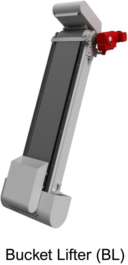
The Bucket Lifter (BL) is designed to lift material from A to B by means of one or more buckets. Compared to the Chain Bucket Elevator or the Belt Bucket Elevator, the Bucket Lifter is specifically designed for lifting smaller quantities of material.
The Bucket Lifter is a simple and cost-efficient method of lifting material from point A to point B.
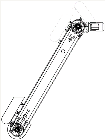
The Bucket Lifter consists of a gear motor, bucket(s), a chain/belt and a steel construction. A loading station in the bottom ensure that the bucket(s) is being dosed correctly. The bucket(s) are lifted to the top where it is emptied when it is tilted around. After a preset time, tilted, the bucket reverses and returns to the bottom, ready for the next filling. If the Bucket Lifter has more than one bucket, each bucket is being emptied one after the other before the all the buckets are return to the bottom section.
The Bucket Lifter is designed as a strong frame construction, manufactured by either stainless or painted steel.
Drive unit: Geared brake motor
Voltage: 400/230V-60/50Hz or as required
Sensor: 4 x limit switches
Height: 1 – 20 m
Frame/bucket: Stainless steel/painted mild steel
Our sampling equipment and sampling systems operate in accordance with approved international material standards such as ISO, ASME, GOST, EN as well as DS3077 (2013).
All sampling equipment and solutions aim for compliance with the principles laid down in the Theory of Sampling (TOS) and gives our customers reliable knowledge of the material properties such as moisture content, particle size distribution, mineral proportions, and content grade essential for commercial, operational, and technical characterization.
- The Bucket Lifter Single (BL-S) has one bucket that is mounted on a belt that pulls the buckets back and forth between A and B.
- The Bucket Lifter Multiple (BL-M) has several buckets that is mounted on a belt that pulls the buckets back and forth between A and B.
Those familiar with mill-practice understand the work required of an average bucket elevator, but I wish to call special attention to the wear on the buckets. I have been studying in what manner the life and service of the bucket might be improved, and I feel that an adjustable lip, attachable to each bucket without the aid of rivets, will be of material advantage.
How to Size a Bucket Elevator
Honestly, I truly have no idea How to Size a Bucket Elevator, but if you visit these two websites, you will find what you need:
Replacement Buckets
For illustration (Fig 1 & 2), consider the feed-elevator of a typical mill in the Coeur d’Alene district. The ore is carried by water in a launder from the feed-rolls and dumped in the “ boot ” of the elevator, directly in front of the ascending bucket. Middlings from the return-rolls are similarly handled. Under this condition the bucket not only carries the ore, but also picks it up, and this latter requirement determines the life and service of the bucket. It might be said that it would be better practice to convey the feed to the elevator and dump it directly into the bucket, but at one mill at which this plan was tried the results were disappointing and the rubber belt was badly worn.
The wear of the bucket is confined to the lip and the corners which have to pick up the material. When the lip on a corner of a 7- by 12-in. malleable cast-iron bucket is worn down about 3 in., the bucket is of no further value as a carrier and has to be replaced. The worn bucket, containing about three-quarters by weight of the metal of the original bucket, has a scrap value of about 10 per cent, of that of a new bucket. To the cost of the bucket, however, should be added the time-cost of replacing the old bucket by a new one. This time-cost is considerable when the loss per hour, to cease operating the mill.
It is out of the question to put lips on a bucket unless the latter was originally fitted with this device. For if it is attempted to fit lips upon buckets not originally provided with them, it will be necessary to drill holes for rivets and then spend considerable time fitting the lips to the irregular contours of the worn buckets. The improvement suggested is an adjustable attachment which can easily be fastened to, or removed from, the base of a bucket without the use of rivets. This attachment, to be made of a high-grade steel drop-forging or casting, will combine toughness, hardness, and tensile strength. The base of the bucket may be a cheap casting,

possibly ordinary cast-iron. This combination of lip and base will not increase the cost of the improved bucket much, if any, above that of the ordinary bucket now in use, but will increase the life of the bucket, doing the same amount of work, about 400 per cent., with a corresponding decrease in time lost in changing buckets.
This improved bucket is illustrated in Fig. 1, which shows a projection of the bucket with the attachment in place. Two bolts, one on each side of the elevator-belt, pass through the base and attachment and hold both fast to the belt. These end-bolts are 0.25 in. longer than the others. Fig. 2 shows the bucket with part of the lip removed, illustrating the manner in which it is fitted to the base and the opening at A which receives the lug A. There is another opening at B, which is not shown.
Probably a more desirable arrangement than this would be to place the attachment inside the base, in which case the outside of the lip and the inside of the base would be rabbeted.
I am indebted to Stanley A. Easton, (General Manager of the Bunker Hill & Sullivan mine, for the following data, which bear out my statement, and show that others have been trying to improve the service of elevator-buckets. He says that they use there 7.75- by 17-in. malleable cast-iron buckets, which give approximately 80 days’ continuous service on middlings-elevators,

in the old mill, handling 350 tons per day. Placing a manganese-steel lip on one bucket in a set of 72, added 35 days’ service to the 80 days for the whole set.
On this basis, the total cost for elevator-buckets in the concentrators of the Coeur d’Alene district must high. The saving by installing improved buckets can easily be estimated.

