Table of Contents
A detailed Bin Hopper Flow Design & Engineering Study: The mining industry in the United States alone produces nearly 4 billion tons of new bulk materials annually that has a mine-mouth value in excess of 20 billion dollars. The potential for realizing substantial savings in mining and processing costs through improved materials handling systems design is high, especially in view of the current state of the design art.
Where repeated handling of materials is required, the force of gravity generally is utilized. Most frequently the employed type of gravity materials handling system is the bin hopper and its underground equivalent the ore pass chute.
The purpose of this report is to provide a brief state-of-the-art assessment and critique of prediction methods in gravity flow bin hopper engineering.
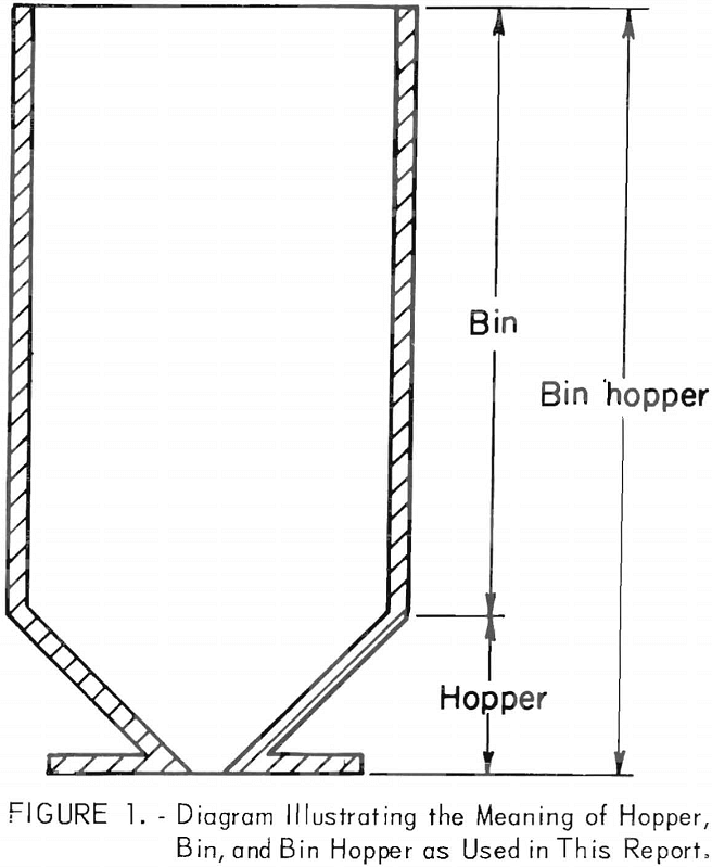
Bins, hoppers, silos, and bunkers are set forth in terms of their application to gravity-operated materials handling and storage systems. The term hopper as used in this report refers to a relatively shallow wedge, cone, or similar-shaped structure that converges to a discharge orifice. Bin refers to a tall, usually vertical structure attached to a hopper, and bin hopper refers to the combination. In a broader sense, hopper refers to the outlet region of silos and bunkers whereas bin refers to the region beyond the outlet zone. Figure 1 illustrates the meaning of hopper, bin, and bin hopper as used in this report.
Engineering problems associated with bin hopper design fall into two broad categories:
(1) Functional design problems and (2) structural design problems. The latter is associated with the analysis of stress and deformation in the bin hopper walls and supporting members; whereas the former refers to considerations of flow-no flow (flow will take place only when the yield strength of the solid in the channel is too small to support an obstruction to flow) criteria, flow regimes, and flow rate requirements for the materials handled. Flow-no flow and flow rate considerations obviously are important. The necessity for flow regime considerations arises from phenomena such as piping, ratholing, funneling, flooding, and aerating. Segregation and problems of blending generally are ignored although segregation-often a serious practical problem in the storage and handling of granular materials-can be considered, to a certain degree, as a flow regime question. Functional and structural design are related and collectively constitute a general small-scale system design problem.
Vibrators, various types of inserts located towards or near the orifice, and mechanical, pneumatic, and other types of feeders—devices for insuring egress of material from the hopper-are excluded from consideration in this report. However, it is recognized that even in the presence of a feeder, one still relies upon gravity to move material into the zone of feeder action. If in the design process one can replace the feeder action by equivalent stress and velocity fields, then much of what applies to free discharge gravity bin hoppers also can be applied to controlled discharge bin hoppers. However, the presence of a feeder generally alters the flow patterns and should be considered in any practical installation. Flat-bottomed bins with one orifice opening often are used such as those used for ores; however, since little has been done to analyse these bins, this report will not discuss them and their study remains an area of potential research.
The materials handling efforts of the mining, agricultural, chemical, and process industries of the world are enormous. In the United States, the domestic mining industry alone produces nearly 4 billion tons of new bulk material annually that has a mine-mouth value in excess of 20 billion dollars. This tonnage and value are increased many times through rehandling and processing. The total cost is immense and the potential for realizing significant savings through improved systems design is substantial, especially in view of the current state of the design art. Materials handling often accounts for more than one-half of the full cost of the product.
Lower materials handling costs mean lower overall mining and processing costs. Moreover, reductions in the cost of mining and processing make marginal mineral deposits potentially profitable ore reserves, thus expanding the Nation’s vital domestic mineral resources. The margin between profit and loss in the exploitation of large, low-grade ore deposits frequently is of the order of cents per ton. Such a small difference multiplied by the huge tonnages involved amounts to a sizable sum. Likewise a small reduction in the cost of handling large tonnages of bulk materials amounts also to a sizable sum. On a national scale this represents an enormous potential benefit to the Nation’s economy.
Where repeated handling of large tonnages of low-grade materials is required, gravity, the cheapest of energy sources, is utilized The most frequently employed type of gravity materials handling system is the bin hopper or its underground equivalent the ore pass-chute. In order to realize the potential benefits of materials handling cost reductions, improved bin hopper design methodology and technology must be obtained. Full realization of potential benefits, however, will not occur until optimum structural and functional design of bin hoppers becomes routinely feasible. Too often a bin hopper is added after the rest of the system has been designed and installed. This often has led to improper or ineffective bin hoppers and even to bottlenecks. where the expensive revisions of other parts of the system had to be made belatedly. In view of the present state of the predictive art in bin hopper engineering and of the limited but crucial ongoing research in the field, it appears that ultimately bin hoppers can be engineered to fulfill their technologic functions reliably and at minimum cost, but much additional research is required.
The literature concerning various aspects of bin hopper engineering spans at least a century and is diffused through a wide variety of publications pertaining to agriculture, mineral, chemical, and process industries. Even if desirable, a paper by paper review would not seem possible within practical time limits However, one can outline the historical development of the field and indicate the events of major proportions in a relatively few lines. The original functional problems connected with bin hopper engineering were those of flow-no flow and flow rate prediction. Empirical methods predominated for many years. In 1961 the publication of a landmark document by A. W. Jenike initiated the modern trend in the analysis of functional bin hopper engineering problems including flow regime considerations. Since then there has been a sizable international growth of interest in functional and structural bin hopper engineering as evidenced by selected papers presented at recent symposiums; for example, on powder flow and storage at Bradford, England, in 1967, on flow and handling of solids at Boston, Mass., in 1969, and on mechanics of granular materials and powders, in Czechoslovakia, also in 1969.
The motivation for this activity may be found in the greatly increased need for precise, reliable, and predictable bin hopper behavior due to automated plants, more stringent feed specifications, increased costs of labor and downtime, and in general, the requirements of modern industry. A second and equally important source of motivation is the development of an awareness among significant numbers of engineers and scientists that the mechanical behavior of materials handled in bin hoppers is not something to be ignored but should be treated objectively similar to other engineering problems designs made according to the phenomenological behavior of the bulb materials
Structural aspects of bin hopper engineering follow a more traditional development. The dominant questions have centered upon bin hopper and silo loads and methods for predicting these loads. Yet despite the maturity of the subject, design codes for grain silos and bins still are controversial. The celebrated Janssen formulas, which are known to be in serious error on occasion, remain to be displaced or improved upon. They describe the vertical pressure profile at any given cross section for all types of particulate beds. An accumulating body of evidence indicates that bin hopper wall load prediction will require a considerable increase in sophistication of analysis and computation before accurate calculations can be performed on a routine basis.
This report is composed of two parts: The first part consists of a review and critique of existing empirical approaches to functional bin hopper design, and the second part consists of a review and critique of the phenomenological approach to functional bin hopper design. Emphasis is upon free gravity flow. Effects of gas counterflow encountered in handling very fine particulate materials are not considered.
Review of the Empirical Approach
Existing prediction methods upon which functional bin hopper design procedures are based can be classified as empirical or phenomenological. Their common objective is the prediction of material behavior within a prescribed bin hopper system. Both methods are characterized by certain limitations and successes with respect to flow-no flow, flow rate, and flow regime considerations.
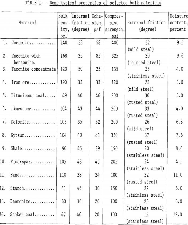
Prediction procedures classified as empirical are those, to a great extent, based on experience, intuition, and limited observations without particular regard for the principles of deformable body mechanics. Empirical procedures are numerous, a testimony to the great variety of materials handling in bin hoppers and the differences in their properties (table 1) and to the large number of authors who have investigated various aspects of bin hopper function. Empirical procedures also are characterized by simple mathematical formulas that often are supplemented by lengthy qualitative descriptions of what is imagined to be the mechanics of bin hopper flow processes. As Jenike points out in an earlier introduction to functional bin hopper engineering, much of the empirical work is given adequate treatment in a chapter of a book by Zenz and Othmer. Simplicity and ease of application are the principal advantages claimed for the empirical approach. The strongest criticism of this approach is that the results are of limited utility; that is, they generally can be applied only to the materials and bin hoppers used under specific conditions. Little predictive value outside the framework of the experimental design is present.
Flow-No Flow Criteria
A flow-no flow criterion is a rule or formula for specifying the discharge orifice size and hopper slope required for a material of a certain yield strength for flow to occur whenever the discharge gate is opened. Empirically developed flow-no flow criteria are simply rules of thumb that pertain almost exclusively to granular materials lacking cohesion; a strong limitation in many practical applications. Even in those materials generally termed cohesionless, such as dry sand, an interlocking effect through dilation produces an apparent cohesion when shearing or flowing occurs which means the material acts as though it had true cohesion. This effect is particularly pronounced in granular materials under low compressive stresses such as those found in common bin hopper configurations. When flow-no flow criteria are implemented, they are intended to insure flow against stoppage due to the mechanical interlocking of particles and fragments in the vicinity of the hopper outlet. Stoppages due to the formation of cohesive domes and arches are not encompassed by empirical flow-no flow criteria. The consensus appears to be that for approximately equidimensional fragments and particles, the least dimension of the outlet should be no less than 4-½ times particle diameter.
Examples of cited criteria are as follows:
- Clogging is prevented by maintaining an outlet width three times the maximum diameter of the largest particle.
- Outlet width should be 4.21 times the largest mesh size of particle
- An outlet to particle diameter ratio between 4 and 6 will prevent interlocking.
- A ratio of outlet dimension to intermediate particle dimension of 3 to 6 will prevent interlocking.
- An outlet to particle diameter ratio of 5 will suffice to prevent interlocking in most cases.
- A ratio of outlet to particle diameter of 3.6 to 4.5 will prevent interlocking of spheres flowing through a circular orifice.
Flow Rate Formulas
Empirical flow rate formulas are intended for use in estimating the size of outlet with a given hopper slope required for a specified flow rate. Existing formulas are restricted to granular materials lacking cohesion and are based on dimensional analyses coupled with experimental trials. Only steady flow rates are considered. Mathematical models obtained by statistical curve fitting, using appropriate parameters over feasible ranges, virtually are nonexistent. Part of the problem is that with such approaches there exists the necessity of understanding any transitions in the mechanics of flow caused by material property differences or alterations in flow regimes. Zenz and Othmer present a useful summary of a number of empirical flow rate studies in the form of a correlation plot between two dimensionless parameters, one containing the flow rate (Q). The plot (fig. 2) is a straight line on a log-log plane and represents the better of empirical flow rate estimation procedures in terms of reliability and scope. Unit weight of materials ranged from 45.5 to 420 pcf, particle
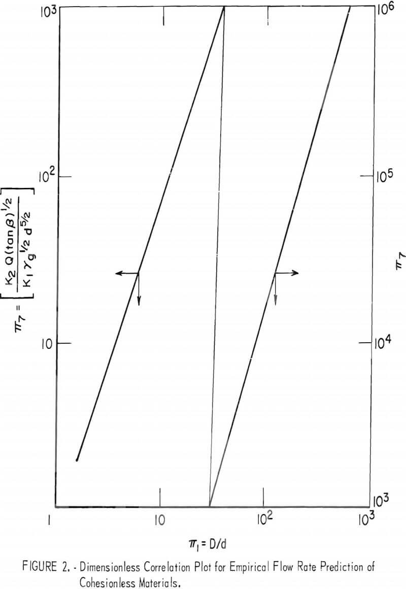
diameters from 0.005 to 0.591 inch, and angles of repose from 23 to 42 degrees. Bin hoppers generally were circular and fitted with centered, circular outlets. Hoppers were sloping as well as flat-bottomed. The ratio of outlet to particle diameter ranged from approximately 6 to 200, and some evidence exists that extrapolation to higher values is possible. At values lower than 6, flow stoppage caused by interlocking becomes highly probable.
The approach utilized in deciding upon the experimental trials leading to the construction of figure 2 is standard. Suppose it is decided that the important variables in the problem of estimating the outlet size required for a given flow rate Q (weight basis) are: (1) Outlet diameter-D; (2) bin diameter-B; (3) hopper slope angle-α; (4) particle diameter-d; (5) bulk density-γ; (6) angle of repose-β; and (7) gravity-g. A functional relationship among the chosen variables is symbolically:
F(D, B, α, d, p, β, g, Q) = 0………………………………………………………….(1)
If the fundamental units of the system are taken as mass-M, length-L, and time-T, then a straightforward dimensional analysis shows that

where the pi-terms (π) are linearly independent and dimensionally homogeneous products of powers of the chosen variables. For example, let

which are clearly independent, since each term contains a variable not included in any of the others. Tan d and tan β or powers of these functions instead of α or β alone could have been used equally well without affecting the generality of the discussion.
If the underlying physical laws governing flow rate are independent of scale, then the pi-terms constitute the requirements for similitude between model and prototype bin hopper systems. In fact, any dimensionally homogenous combination of variables constitutes a similitude requirement. For example, combining foregoing terms 1, 2, 3, and 4 and using tangents of angles results in

This pi-term is on the order of an educated hypothesis since a multitude of such terms exists, For a bin of specified geometry, excepting the outlet dimension which is to be determined in order to achieve a prescribed flow rate of a given material, there results

where the substitution of unit weight γ for the product pg has been made. K1 and K2 now can be viewed as correction factors for hopper slope angle and bin diameter. When experimental values of π7 are plotted against π1 = D/d, figure 2 is obtained, which is the correlation plot of Zenz and Othmer who have correction factors for hopper slope angle but not for bin diameter.
Flow Regime Considerations
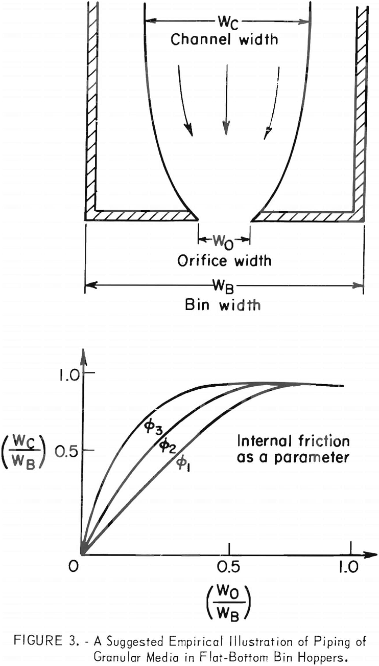
The prime consideration of flow regimes pertains to the question of whether or not the material will flow over the entire cross sectional area of the bin hopper. When the material flows downward so that particles are always moving along the sides of the bin hopper, it is called mass flow. When the material flows downward but with somewhat of a conical depression of varying diameters in the center of a symmetrical hopper and with no material movement along the walls, it is called funnel flow, which is the type of flow that occurs in practice most of the time in bin hoppers and silos. Failure to flow over the entire cross sectional area is one of the principal causes of functional bin hopper maloperation and also is known as piping. Published empirical studies supporting reliable no-piping design formula are practically non-existent, though a number of descriptive and case study reports can be found scattered throughout the literature. One ongoing study intended to relate the ratio of flow zone width to bin width as a function of the ratio of outlet width to bin width with hopper slope angle and internal friction as parameters is expected to help solve the problem as far as cohesionless materials are concerned. Figure 3 illustrates the information that such a study would provide.
Critique of the Empirical Approach
There is little that can be said in criticism of specific empirical studies conducted in attempts to establish reliable, predictive formulas concerning functional bin hopper design. In a certain sense, each such study is a self-contained entity and stands on its own. This is precisely the difficulty and constitutes the classic disadvantage of the empirical approach. Even though a large number of trials involving a large range of variables may be encompassed by an empirical investigation, an uncertainty of unknown magnitude always exists in the extrapolation of results to conditions even slightly different from those originally investigated.
The problem of choosing the significant variables from the multitude available in an empirical study should not be overlooked. In fact, results cited here are exclusively concerned with cohesionless media. Applied to a larger class of materials, the formulas would undoubtedly fail to provide reasonable estimates of flow-no flow conditions, flow rates, and flow regime
behavior. For example, the flow-no flow criterion given for cohesionless media in terms of a critical ratio of hopper outlet to particle diameter certainly is not applicable to fine particle media such as powders capable of supporting tensile stresses. Materials properties usually are relegated to a minor role in empirical studies; emphasis tends to be placed upon geometry. The empirical flow rate formulas were developed almost solely for cylindrical bins having centered circular outlets.
Numerous latter-day empirical studies of interest in themselves do not fit readily into any of the three subdivisions of functional bin hopper design considerations but deal instead with secondary or contributory factors that ultimately may or may not prove to be significant and useful. Other studies of a semi-empirical nature not directly related to functional predictions represent novel views and attempts at characterizing bulk materials in unusual ways. An intriguing example of the latter is described by Scarlett and Todd who propose a relationship between critical porosity of a flowing aggregate of particles and a statistical chord size distribution of the flowing aggregate. An example of the former that deals with such important but difficult to quantify phenomena as adhesion and agglomeration during flow is the survey presented by Pietsch.
In summary, the empirical approach toward the development of reliable, predictive bin hopper design formulas-including flow-no flow criteria, flow rate formulas, and flow regime consideration—at best has produced a rule of thumb to prevent flow stoppage due to interlocking of cohesionless particles, and a method for estimating the rate of flow of cohesionless media through cylindrical bins fitted with centered circular discharge orifices. Thus, useful formulas are restricted to a special class of materials stored and transferred in bin hoppers of limited geometric variation. The historical lesson should be clear. In spite of over a century of application of the empirical approach by numerous investigators, some of whom have painstakingly correlated their work with that of others in the field, the broadly applicable results required for general bin hopper engineering design have not be forthcoming. Nevertheless, the results that have been obtained are useful, and until a more general approach is formulated and tested, empirical formulas and experienced engineering judgment will be much in demand. There is the possibility that numerous combinations of the physical properties measurements, coupled with stress and velocity fields and other quantities within the bin hopper, could be used as parameters in a generalized empirical equation and a computer equation would be obtained by rejection of the insignificant terms. The greatest weakness in this approach is that it does not analyze the system physically, so that any change in regimes during flow is unknown and restricted sets of equations are obtained.
Review of the Phenomenological Approach
In the phenomenological approach to bin hopper engineering, the material handled is replaced mathematically by an idealized medium that deforms and flows in accordance with the principles of continuum mechanics. A phenomenological theory is one in which all the magnitudes for the casual chain must be observable; none can be inferred. For instance, the kinetic theory of gases postulates invisible disorderly movements and collisions of molecules and so is not a phenomenological theory. This type of theory is restricted to the macroscopic properties which appear in the commonplace level of experience. Classical thermodynamics is a phenomenological one. The equations connect only observable magnitudes. Usually, but not always, in the other theories the macroscopic properties are dissected and microscopic entities are postulated to represent the fundamental reality behind the macroscopic appearances. Sometimes the phenomenological approach is loosely defined as one of using idealized mathematical models obtained by theoretical analysis as contrasted to empirical approaches which depend primarily on experiment and data analysis.
A statistical argument is implied in that small volumes of the actual material are assumed to contain a sufficiently large number of individual particles to be representative of the material in the neighborhood of a point. All field quantities such as stress and strain thus refer to averages over a small volume about a point. The smallest dimension of a bin hopper is usually the width of a slot outlet or the diameter of a circular outlet. If the diameter of the largest material particle in the bin hopper is an order of magnitude less than the least dimension of the outlet, then the outlet will be well above the size required for the prevention of interlocking of particles and continuum concepts probably will be applicable. A representative volume, by the preceding order of magnitude argument, would contain at least a thousand particles. It is the same view that is tacitly invoked in the application of continuum or phenomenological theories to any material; for example, these theories are used in the elastic analysis of steel beams. Steel is composed of discrete grains, but in the aggregate of large numbers, such as those in a ¾-inch-diameter tensile test specimen, in this instance the material is adequately characterized as a continuum. The relatively large grain sizes often encountered in bulk materials handling problems necessitates an explicit recognition of the conditions under which a phenomenological approach reasonably can be assumed to apply, especially since there are important practical cases where the identity of individual particles must be maintained.
The traditional phenomenological descriptions of continua reside in the elastic, plastic, and viscous mathematical models of materials. Elastic materials are conservative in the thermodynamic sense; no net work is done on an elastic material over a cycle of loading and unloading. Elastic materials regain their original shape upon loading. Plastic and viscous materials are dissipative; hence, net work is done of these materials over a cycle of loading and unloading. Plastic and viscous materials, moreover, are capable of permanent deformation and thus may not regain their original shapes upon loading, whereas elastic and certain types of plastic materials are time independent in the mechanical sense and are incapable of supporting shear stresses indefinitely. Real materials, of course, are complex and exhibit time, temperature, and other environmental effects to varying degrees. The variation in bulk density at various locations within the mass caused by a non-uniform pressure field is not considered in any of the analyses.
However, if the idealization of the particular problem at hand is an intelligent one, then reasonable information can be obtained and reliable predictions made.
Because of the permanent and postyield nature of the deformation associated with flow processes of bulk materials in bin hoppers, an applicable idealization is that of plasticity theory. In fact, the modern trend in bin hopper engineering initiated in 1961 by A. W. Jenike is based upon a variant or adaptation of classical plasticity theory to bulk materials. The landmark document was his “Gravity Flow of Bulk Solids”. Only wedge-shaped and conical bin hoppers were considered. Important computational details may be found in “Stress and Velocity Fields in Gravity Flow of Bulk Solids”. A condensed and less mathematical version of reference 6 is “Storage and Flow of Solids”. These works by A. W. Jenike, J. R. Johanson, and A. W. Jenike, and A. W. Jenike, respectively, are the essential documents in the field of functional bin hopper design, with the exception of the work by J. R. Johanson. Much of their success seems to lie in their practical experience since there are restrictive assumptions involved in their formulas.
Other authors also have utilized plasticity theory in various forms for the analysis of the mechanics of bulk materials flow. Not all of these studies were aimed directly at the solution of practical bin hopper problems through immediate development of design formulas. A number were concerned with the more fundamental question as to the general applicability of plasticity theory to the mechanics of bulk materials. In such instances, the bin hopper served as a useful but incidental experimental vehicle. The accumulation of experimental evidence from these latter investigations indicates that plasticity theory is indeed a useful framework for the analysis of bin hopper problems satisfying the conditions for applicability of the phenomenological approach. Wide applicability and improved understanding are the principal advantages claimed for the phenomenological approach. The screening out and testing of the fines to obtain values for parameters used in the Jenike formulas is questionable. He assumed that the coarse particles are carried along by the granular material movement and that the maximum shear strength is determined by the fines. The presence of coarse material will influence these parameters, and even when they are not touching, except here and there, the larger particles do affect the flow. The application of plasticity theory and obtaining meaningful stress distributions and velocity fields thus is complicated.
Flow-No Flow Criteria
The specification of hopper outlet size sufficient to prevent stoppage of flow is in the phenomenological view tantamount to the specification of outlet dimensions necessary to prevent the formation of stable, cohesive domes or arches over the discharge orifice. Domes caused by mechanical interlocking of particles are not explicitly recognized but nevertheless are accounted for in view of the conditions established for the applicability of the phenomenological approach and empirically based flow-no flow criteria for cohesionless media. The outlet thus will be sufficiently large to prevent interlocking; the question is: How much larger must the outlet be in order to insure gravity flow of a cohesive medium?
Flow-no flow criteria per se are developed easily out of hand for cohesive media. Mathematical complexities reflecting the physical subtleties of the situation enter into the analysis at a later stage. One approach that can be used is to consider a dimensionless ratio of forces-those tending to cause flow and those tending to impede flow. Since free gravity discharge of bin hoppers is under consideration, the weight of material characterized by its specific weight γ tends to cause flow; whereas the strength of material, say, unconfined compressive strength Co tends to resist flow at the hopper outlet which has a characteristic dimension D. To account for different shapes of outlets, a shape factor K will be employed. Let the dimensionless ratio of forces be N, then
N = (υD)/KCo)…………………………………………………………..(7)
If the force of gravity is large relative to the strength, then N>>1, and flow will occur readily, or if N<<1, implying that a relatively strong material is under consideration, then gravity flow will be impossible. With a value of N equal to unity being decisive, a phenomenological flow-no flow criterion is
D>K(Co/γ)………………………………………………………….(8)
which states that for free gravity flow to occur the characteristic dimension of the outlet must exceed the ratio of unconfined compressive strength to unit weight of material multiplied by a constant. The criterion is identical with that of Jenike developed from a more explicit conception of hopper outlet conditions during flow. With K equal to unity, D corresponds to the width or lesser dimension of a slot outlet. With K equal to two, D corresponds to the diameter of a circular outlet.
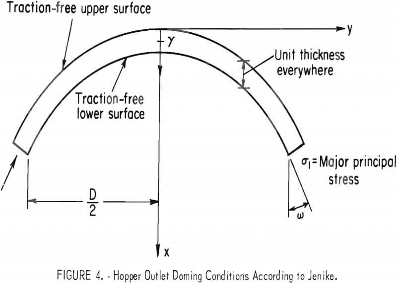
The flow-no flow criterion of Jenike is derived in final form from considerations of static equilibrium of the layer of material just above the outlet. The material is assumed to be at the yield point, and the layer is supposed to have a thickness of unity and to form a free-standing dome; that is, loading is due to gravity only and support is supplied only at the dome abutments which are located at the edge of the discharge orifice. Figure 4 illustrates the situation for either slot or circular orifices. Equating the vertical components of dome weight and abutment reaction, one obtains an expression for the major principal stress σ, in the dome, thus
![]()
where ω is the angle from the x-axis to the line of action of the major principal stress; m is zero for slot outlets and one for circular outlets. D is either the slot width or outlet diameter.
The basic form of the Jenike flow-no flow criterion is due to the requirement that for flow to occur the major principal stress must equal or exceed the unconfined compressive strength, thus
σ1 ≥ Co…………………………………………………………..(10)
is the Jenike flow-no flow criterion, where compressive stresses obviously are positive in sense. Substituting into one finds that it is sufficient to have
D > (l + m) (Co/γ)………………………………………………………..(11)
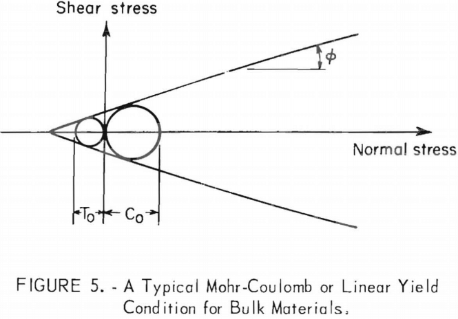
Other phenomenological flow-no flow criteria such as or can be displayed without difficulty, but nothing essentially new will be found nor can the accuracy of such criteria be improved. For example, if a Mohr-Coulomb yield condition is assigned to the material (represented graphically in fig. 5), the angle of internal friction ∅ is introduced into the criterion and is defined as the slope of the yield envelope in the shear stress-normal stress plane (fig. 5). Formula then might characterize the strength of the material by its cohesion k and internal friction ∅ instead of unconfined compressive strength Co, to obtain

which is obtained by substituting the usual expression for Co into. Formula (12) shows that a cohesionless material is free-running, but that a cohesive material even with an angle of internal friction of zero will require a definite sized outlet for flow. Moreover, for a given cohesion, the bulk density remaining the same, a higher angle of internal friction will require a larger outlet diameter. The latter is simply another way of stating that a material with a high unconfined compressive strength will require a large outlet. So nothing really new has been obtained although at first glance it may appear otherwise.
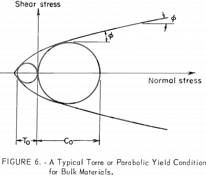
A material with a parabolic or Torre yield condition (fig. 6) would have a flow-no flow criterion in the form of

where ∅c is the inclination of the yield envelope to the Mohr stress circle corresponding to the unconfined compressive strength of the material. (In the parabolic case, Co = (2k/(l-sin∅c)), whereas in the linear case Co = (2kcos∅/(l-sin∅)) in which ∅ is a constant.) According to (13), materials that exhibit a parabolic yield envelope require, for equal cohesions and bulk densities, larger outlets for larger reference angles of internal friction ∅c a result similar to that obtained for materials exhibiting linear yield relationships.
The phenomenological flow-no flow criteria and or their variants and, though simple in appearance and formulated with relative ease, mask formidable obstacles to implementation. In general the material properties, especially the unconfined compressive strength, will be a function of the state of stress at the outlet and of the compaction the material has undergone in its traverse of the bin hopper to the outlet point. The real problem of sizing an outlet in advance of experience is then twofold, consisting of predicting (1) the state of stress and (2) the deformation field throughout the bin hopper. This twofold task presupposes a knowledge of the variation of strength with deformation; that is, one presumably has available a strain hardening or equivalent rule and an experimental procedure for its routine determination. In principle, computation of stress and deformation fields can be accomplished with sufficient effort. The critical requirement for successful flow-no flow prediction then is one for a reliable strain hardening type of rule relating strength to compaction.
In the work of Jenike, the requirement for a hardening rule is met through the introduction of an effective yield locus (EYL), a condition that is supposed to apply to materials undergoing steady flow. In practice, the EYL is approximated by a straight line passing through the origin and of slope tan δ in the normal stress-shear stress plane. The angle δ always is greater than the angle of internal friction ∅ for cohesive materials. In the case of cohesionless materials, δ=∅. Experimental procedures for the determination of the EYL are described in detail. Variations have been proposed. Once the EYL has been determined, the flow-no flow design procedure of Jenike becomes a cut-and-dry affair that involves the hopper slope angle and coefficient of friction between material and hopper wall as well as unit weight of material.
The flow-no flow design procedure of Jenike also involves an estimate of stresses in the outlet region of the hopper. For this purpose, Jenike employs the EYL in conjunction with a radial stress field described in a different context by Sokolovski. A radial stress field is one in which the stresses within a hopper decrease linearly towards zero at the vertex of the hopper. The radial stress field is given by the expression
σ = γrs (θ)……………………………………………………………(14)
where σ = ½(σ1 + σ3) is the mean normal stress in the plane of deformation, σ1 and σ3 are principal stresses, γ is the unit weight of material, r and θ are coordinate variables, and s=s (θ) is a function to be determined for the particular bin hopper under consideration. According to Jenike, compressibility of most bulk materials has a negligible influence on the function s, so that the unit weight of the particular material in the bin hopper is constant. Incompressibility also is an assumption made in the computation of Jenike velocity fields. This is an approximation since pressure can force smaller particles into voids or cause fracture and plastic flow. Charts incorporating radial stress field computations as contours of “flow-factors” on the plane have been prepared as aids to design. The angles θ’ and ∅’ are the hopper slope angle as measured from the vertical and angle of wall friction, respectively. Example problems illustrate the Jenike flow-no flow design procedure and chart usage.
Because of the length of the Jenike flow-no flow development, the essential steps without supporting details are listed here (in the notation of Jenike):
Establishment of the flow-no flow criterion,
B ≥ (l+m)fc/γ……………………………………………………………………….(15)
where B = slot width or diameter,
fc = unconfined compressive strength,
γ = specific weight,
and m = 0 for slot outlets or 1 for circular outlets when θ’ is zero.
Introduction of the effective yield locus-EYL,
(σ1/σ3) = (l+sinδ)/(l-sinδ)……………………………………………………….(16)
where σ1 = major principal stress during steady flow,
σ3 = minor principal stress during steady flow,
and δ = effective angle of internal friction.
Introduction of the radial stress field,
σ = γrs(θ)…………………………………………………………………..(17)
where σ = ½(σ1 + σ3)
and r, θ = polar coordinates
Introduction of the flow-factor concept,
ff = σ1/fc………………………………………………………………(18)
where ff = flow-fartor
and ffc = critical flow-factor, occurs whenever the equality holds in (15)
Combining the above relationships an expression for the critical flow-factor obtained is:
ffc = (l+m)(l+sin δ)s(θ’)/2sin(θ’)……………………………………………(19)
The primes refer to values taken at the hopper walls, that is, is the hopper slope angle as measured from the vertical. The hopper wall friction angle ∅’ as well as θ’ will influence the value of s (θ’). The critical flow-factor is thus a function of material, material-wall and hooper slope parameters.
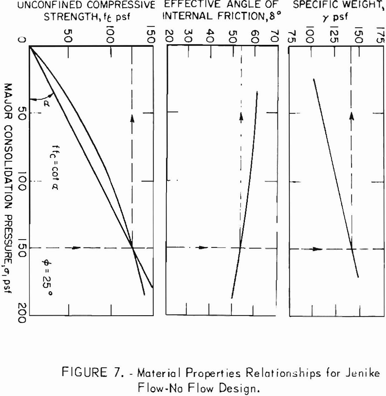
Once experimental values of fc , γ, and δ are obtained as functions of (fig. 7), design can proceed. A set of values (∅’, θ’, δ) determine an initial estimate of ffc which then is plotted as a straight line through the origin on the experimental fc versus σ1 plane (fig. 7). The intersection of this line with the experimental curve of fc versus σ1 determines fc and σ1 for the hopper and material under consideration. The value of σ1 also determines γ on the experimental plot. Using these values of fc and γ, one computes the critical outlet dimension B from (15).
Flow Rate Formulas
The only flow rate formula for cohesive materials within a phenomenological framework of analysis is one proposed by Johanson in 1965. An approximate formula for cohesionless granules was proposed by Brown in 1961. The latter derivation was based upon a minimum energy hypotheses; the first was developed essentially as an extension of the Jenike-Johanson flow-no flow analysis. In the instance of no cohesion, the Johanson formula becomes similar in essential respects to the empirical flow rate formula of Zenz and Othmer and is dimensionally identical with a form of the Zenz-Othmer flow rate design parameter given by equation (6). The same assertion can be made regarding a flow rate formula based upon the derivation of Brown. The derivations of Johanson and Brown are special cases obtainable within a more general but still approximate phenomenological approach, a stream tube analysis of energy change. More sophisticated analysis of bin hopper velocity fields within the framework of plasticity theory have not led to flow rate formulas, although the work of Savage holds promise in this respect. Usually, the stress and velocity fields are coupled only indirectly through the network of principal lines, and thus only a relative velocity field can be computed. In the work of Savage, the customary small velocity gradient assumption is abandoned and a more direct coupling between stress and velocity fields is obtained, though the steady flow assumption is retained. One result of the analysis of Savage in the case of radial stress is that the flow also is radial and unique.
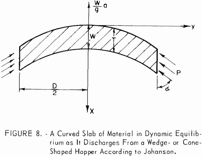
The Johanson formula begins with the analysis of a curved slab of material as it flows from a wedge-or cone-shaped bin hopper (fig. 8). Summation of forces in the vertical direction for a slab of unit thickness and loaded only by self-weight and wall reactions results in
F = W(l – a/g)………………………………………………………………(20)
where F is the wall reaction, W is the weight of the slab, a is the acceleration of the slab, and g is the acceleration due to gravity. If S is the width of a slot outlet of length L below a wedge-shaped hopper, then

if D is the diameter of a circular outlet at the bottom of a conc shaped hopper, then

where Co, is the unconfined compressive strength of the flowing material and y is the specific weight, Since the flow is steady and density changes are considered negligible, the average vertical velocity is
V = K/A………………………………………………………………………(23)
where K is a constant and A is the horizontal cross sectional area at the point V is observed. From and the material acceleration then
a = V(dV/dx) = (-V²/A) (dA/dx)………………………………………………………….(24)
For wedge geometry at the outlet,
a = (2V² tanα/S)……………………………………………………………….(25)
and for cone geometry at the outlet,
a = (4V² tanα/D)…………………………………………………………(26)
where α is the hopper wall inclination measured from the vertical. Substituting in for a slot outlet
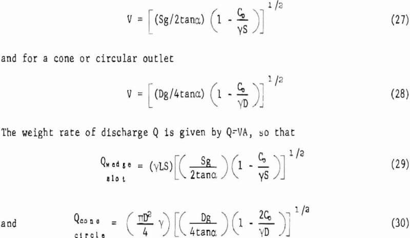
Formulas (29) and (30) can be used to calculate the steady weight rate of free gravity discharge of cohesive materials of unconfined compressive strength from wedge-shaped hoppers fitted with slot outlets and cone-shaped hoppers fitted with circular outlets provided flow occurs over the entire cross section of the hopper. If not, then α is replaced by the effective hopper wall inclination. If the material is cohesionless, then Co = 0 and reduces to


which is dimensionally homogeneous and similar to formula (6) previously derived through a dimensional analysis and verified empirically. The effect of cohesion according to (29) and (30) is to reduce the rate of discharge relative to a cohesionless material of the same unit weight. Wall friction probably has a similar influence in that the greater the wall friction the lower the flow rate.
In the terminology of Johanson, S and D are replaced by B and their terms (Co /γS) and (2Co /γD) by (ff/ffa). The latter is the ratio of critical to actual flow-factors. As in the development of the Jenike-Johanson flow-no flow analysis, formulas (29) and (30) require the determination of γ and Co, at the outlet. This, in turn, is accomplished through a series of steps utilizing plasticity theory and experimental procedures as particularized by Jenike for bin hopper engineering analysis and design. Experimental evidence offered by Johanson is in fair agreement with (29) and (30).
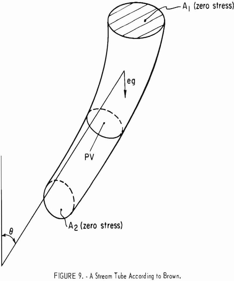
The flow rate formulas of Brown pertain to free gravity discharge of dry granules from wedge- and cone-shaped bin hoppers fitted with slot and circular outlets, respectively. The analysis is limited to bulk materials composed of granules of the same size, but is readily extended to bulk materials of various-size compositions by the continuum approach. The derivation begins with the hypothesis that the sum T of the kinetic and potential energies per unit volume decreases in the direction of flow because of friction on the sides of the stream tube. Figure 9 shows that
![]()
The pressure difference between the surfaces A1 and A2 normal to the stream tube is considered negligible. Jenike and Johanson assume that the pressures on the upper and lower surfaces of a potential dome or slab of material discharging from a hopper are equal to each other and equal to zero. The assumption then is made that the stream tubes are radial. In wedge flow V = K/R and In cone flow V = K/R², where K is a function of θ, but K in cone flow is not the same as in wedge flow. For wedge flow

for wedge and cone flow, respectively. Span S of a slot outlet and diameter D of a cone outlet are given by
S = 2Ro sinσ…………………………………………………..(38a)
and D = 2Ro sin α…………………………………………..(38 b)
where Ro, is the distance from the wedge or cone vertex to the hopper wall and a is the inclination of the hopper wall to the vertical.
Brown asserts that Ro is an upper limit for Rm, so that for wedges

and for cones

Equations (39) and (40) are obtained through an application of Q = γ∫VdA and (36) to (38).
With the exception of the integral factors, formulas (39) and (40) are identical to (29) and (30) for the cohesionless case. In the original derivation of (39) and (40), Brown replaced S and D with (S-k) and (D-k), where k is a small number due to what Brown calls the “effective empty annulus” at the out lot. Brown also intends a to be effective hopper angle in case flow does not occur over the entire cross sectional area of the hopper. In fact, Brown utilized flat-bottomed vessels for experimental observations. The data was in fair agreement with flow rates computed by (39) and (40).
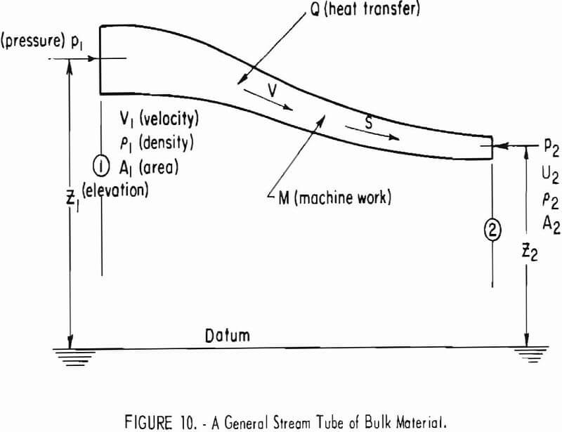
The preceding analyses are special cases of a more general view of energy changes along a stream tube. With reference to figure 10, the conservation of energy E required dE/ds = 0 along the stream tube, thus

for steady flow. The terms in (41) represent flow work; the work equivalent of heat transferred from the system; the change in internal energy; the work done on the tube; the change in gravitational potential energy; and the change in kinetic energy of the system per unit mass of the flowing material. Shears at the boundaries of the tube that produce frictional heating and any internal dissipation of energy are included in the Q and T terms.
In the absence of flow-promoting devices, dM/ds = 0, and for most practical purposes, the flow can be considered isothermal. Near the outlet, Johanson and Brown considered dp = 0 and the flow to be incompressible. These assumptions imply

With disregard of the heat term, the starting point for the analysis by Brown can be obtained. If, however, the heat transfer term is equated to the frictional dissipation of energy at the walls of the stream tube, then
dH/ds = (τP/ρA)…………………………………………………………………………(43)
where τ is the shear stress at the wall, P is the perimeter of the stream tube, p is the mass density, and A is the cross sectional area of the stream tube. If σ is the normal stress at the walls of the stream tube, then t = µσ, where
µ is the coefficient of friction. At the outlet of a wedge- or cone-shaped hopper with axis-z positive downwards and flow vertical, then

where again α is the hopper wall inclination from the vertical. Using V = K/A in (44) and solving for velocity V, one obtains

for circular outlets. At the outlet, the wall shear stress cannot exceed (½)Co.
The weight rate of discharge then is given by

The angle α represents the effective hopper slope whenever flow does not occur over the entire cross section of the hopper. Formulas (46) and (47) yield lower estimates of flow rates than do the Johanson formulas (29) and (30). It is interesting and worthwhile to observe that the flow-no flow criterion established by equation (7) requires the ratio (KCo/γD) to be less than unity for flow to occur, thus there is assurance that the terms in (46) and (47) will be real. Johanson notes that his calculated flow rates tended to be higher than observed flow rates. Because (46) and (47) yield lower estimates of flow rates, they may provide improved estimates of weight rate of discharge. Formulas (46) and (47), presented here for the first time, however, require experimental verification.
If in (41), the pressure term is retained, n number of interesting results can be obtained, including as a special case, the Janssen formulas for bin wall stresses.
Flow Regime Considerations
In the broadest sense flow regime refers to the pattern of flow that occurs during bin hopper drawdown. Distinct patterns of flow observed in empirical investigations of the flow of cohesionless materials in laboratory size bin hoppers reveal the occurrence of at least three readily distinguishable regimes in the vicinity of the discharge orifice. These are illustrated schematically by figure 11. The flow regime of figure 11A is characterized by the presence of one region of uniform flow that occurs over the entire cross sectional area of the hopper. In figure 11B two different zones are present-one is the central region of fast-moving material and the other is a region of much slower moving material adjacent to the hopper walls. In figure 11C three types of zones are present. In addition to a fast-moving central region bounded by zones of slower moving material, regions of nonmoving or dead material occur adjacent to
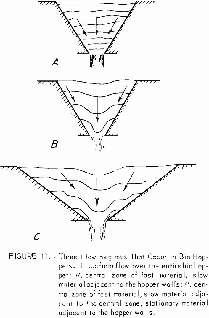

the hopper walls. These three flow patterns have been analyzed within a framework of plasticity theory by several authors, but such analyses, although of interest in a basic way, are not in themselves design procedures.
A functional, engineering classification of flow regimes by Jenike examines the complete bin hopper system and distinguishes between mass flow and funnel flow regimes only. Figure 12 illustrates mass and funnel flow regimes.
Mass flow regimes figure 12A are highly desirable from a practical or engineering standpoint. Material entering the bin first will be the first material to be discharged, thus the bin functions on a first-in-first-out basis. Flow occurs typically over the entire cross sectional area of the bin. Mixing also occurs in mass flow bin hoppers and aids in controlling segregation. Generally mass flow bin regimes require steep hoppers, so that relatively tall, narrow structures result.
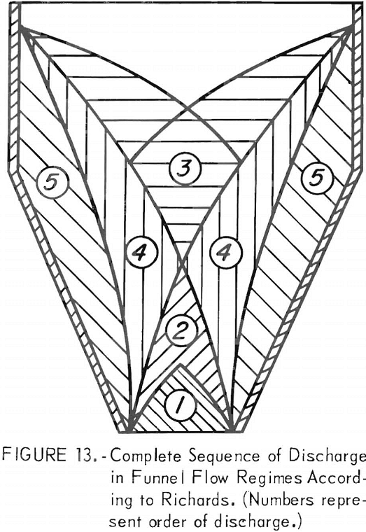
Funnel flow figure 12B is characterized by the formation of a narrow zone of fast-moving material, centered over the outlet that is bounded by zones of stationary mate¬rial adjacent to the bin walls. Material enters the central zone from a funnel-shaped surface that develops at the top of the pipe and discharges from the bin before the material in the stationary zones. In funnel flow the material that first enters the bin hopper is the last to discharge. The complete sequence of discharge in a funnel flow bin according to Richards is shown in figure 13. This is the type of flow which is often encountered in practice but which has not been satisfactorily described analytically.
It may happen, however, that the pipe walls are sufficiently strong to stand unsupported. The central zone empties, but free standing material remains in the zones adjacent to the bin walls Jenike refers to this condition as “piping” and points out
that piping constitutes one of the major causes of bin hopper malfunction—the other is doming. Piping is much less understood than doming and is more difficult to control and to make a design for.
The no-piping design originated by Jenike is based upon an adaption of the phenomenological theory of plasticity to the mechanics of bulk materials and represents the only quantitative design consideration of flow regimes extant. The underlying viewpoint is that a stable pipe will not develop provided the walls of the potential pipe are brought to a point of incipient failure by the discharge of material from the flowing central zone. Should the walls of the potential pipe obtain a state of incipient failure that extends to the bin walls, then stable pipe formation is not a real possibility. Concern, therefore, is with conditions leading to bounded zones of incipient failure, that is, zones not extending to the bin walls.
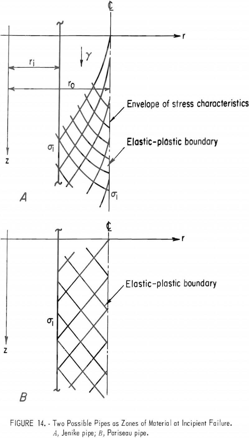
There are at least two physically different ways for a zone of incipient failure to develop at the pipe walls but not to extend to the bin walls. The two cases are depicted in figure 14. In figure 14A the zone of incipient failure of inner radius r1 and outer radius r0 terminates at an envelope of stress characteristics, according to Jenike. In figure 14B, the zone of incipient failure terminates because the stress state beyond the surface r0 no longer satisfies the criterion for failure.
The specific question that the Jenike analysis poses is: What is the smallest radius r1 at which incipient failure still occurs? The implication is that for outlets greater than the least or critical radius, a zone of incipient failure develops and flow ensues. This analysis is as follows:
Consider an idealized circular pipe (fig. 14A) of sufficient length that the stresses do not vary along the length. Symmetry with respect to the axis-z then implies that the stresses do not vary with the angular coordinate ω. There are three equations involving four unknown components of stress-two of equilibrium and one of yield. With the assumption (Harr-von Karman hypothesis) that the circumferential stress is equal to the major principal stress, the system becomes statically determinate in the sense that there are as many equations of stress as unknowns. Manipulation of these equations results in two equations involving Tm and θ (defined below) , one can be used to obtain the radius ri to the traction free inner wall of the pipe, thus

where TM is the maximum shear stress, θ is the angle between axis-r and the major principal stress direction, and γ is the specific weight of material. Equation (48) is indeterminate at r = ri. Application of l’Hospital’s rule results in
![]()
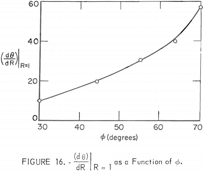
where Co, is the unconfined compressive strength and the dimensionless variable R = r/ri has been introduced. Inspection of (49) shows that the least value of the quantity (dθ/dR)|R=1 will minimize ri. Accordingly, no-piping requires that the hopper outlet radius be greater than min(ri) computed from (49).
The quantity (dθ/dR)|R = 1 can be computed from the second equation obtained from equilibrium and yield, thus

where ∅ is the angle of internal friction. Equation (50) is indeterminate at R=l, so that a simple evaluation is not possible. Moreover, it is necessary to distinguish between integral curves of (50) that lead to bounded zones of incipient failure and those that do not.
With reference to figure 14A, the zone of incipient failure terminates on an envelope of stress characteristics. The slope of the characteristics becomes infinite there and θ assumes a value of π/2 ± µ, where µ = π/4 – ∅/2. Thus, bounded fields are associated with integral curves of (50) that obtain values of π/2 ± µ. The situation is depicted schematically in figure 15. From figure 15 it is apparent that all integral curves of (50) pass through the point (l,π/2). The slope of a curve at (l,π/2) is just (dθ/dR) |R = 1 which serves as the parameter of the family of integral curves defined by (50). It also is evident from figure 15, that the least admissible value of (dθ/dR)|R=1 is associated with the curve A that divides the θ-R plane into bounded and unbounded regions. Curve A intersects the line θ = π/2 + µ, at Ro. Hence, the radius to the outer pipe wall is ri Ro. The value of is obtained by substituting the value π/2 + µ into the expression in brackets in (50) and
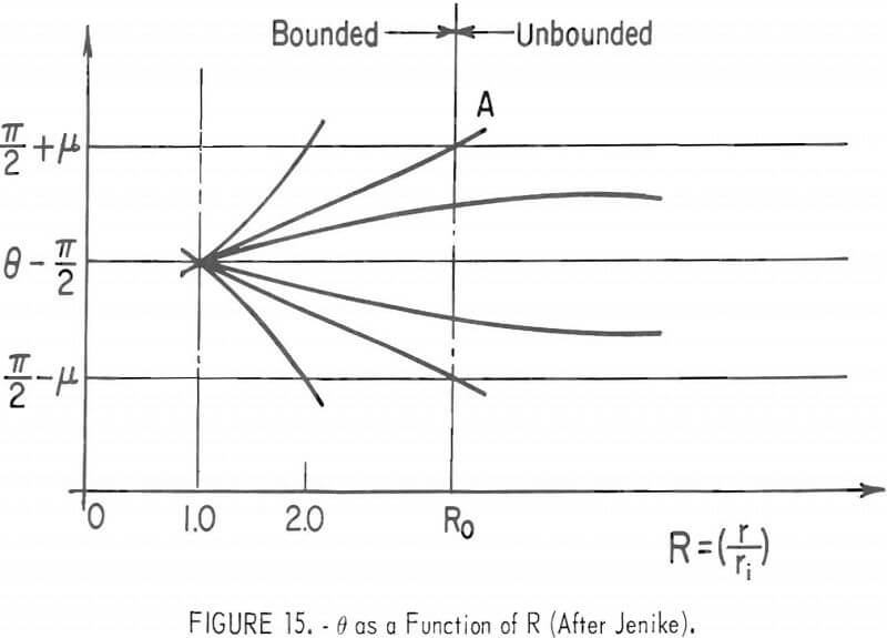
equating the expression to zero, thus
Ro = (2sin∅ – 1)-½……………………………………………………………(51)
Jenike then states that values of the parameter (dθ/dR)|R=1 have been computed numerically and presents a plot (fig. 16) of this parameter versus the angle of internal friction ∅. Figure 16 and equation (49) can be used to design for no-piping, provided the specific weight and compressive strength (γ, Co) that develop in the pipe are known.
The determination of the appropriate γ and Co, proceeds in a manner identical with that for Jenike no-doming design. Experimental values of Co, (fc in the notation of Jenike), γ, and δ (effective angle of internal friction as defined by Jenike) are plotted as functions of the major principal consolidating stress σ1. A critical flow-factor ffc for no-piping (different than ffc for no-doming) is then computed and plotted on the experimental Co, – σ1 plane as a straight line passing through the origin. The intersection of this line with the experimental curve provides the required values of Co, and γ for no-piping design.
Prior to pipe development, the major principal stress at r=ri in the flowing central zone is given by

where δ is the effective angle of internal friction. By definition the flow-factor ff = (σ1 /Co), so that

The value of θ in (53) is approximately π/4+∅/2. However, Jenike recommends the use of simply π/4 on physical grounds. Using θ=π/4 in (53) and (49) there results an expression for the critical no-piping flow-factor, thus

It is implied that the angle of internal friction developed in the material at rest in the pipe be used. If ∅ does not change significantly with time, then

The complete sequence of computations for no-piping design is:
- Experimental determination of flow properties γ, δ, ∅, and Co, as functions of σ1.
- Determination of (dθ/dR) R =1 from graph in (6).
- Determination of ffc by (55) or (54) if time buildup of strength significant (or by graph in (6)) .
- Plot of ffc to point of intersection with experimental curve of Co versus σ1 to find appropriate Co and γ.
- Computation of required discharge orifice radius ri by (49) and appropriate Co, γ, and (dθ/dR)|R=1
Critique of the Phenomenological Approach
The strong appeal of the phenomenological approach, as exemplified in the highly successful pioneering work of Jenike, can be attributed to the great power of generalization inherent in the method. Once the basic material behavior is described, a broad spectrum of bin hopper engineering problems can be formulated and pursued to predictive solutions. Given the computational capability of modern, high-speed digital computers, one can postulate quite complicated models of material behavior. For example, models that include time and moisture effects on anisotropic and heterogeneous materials can be handled, in principle, without difficulty. The assumption of steady flow conditions explicit in the work of Jenike and others could be relaxed, and the progressive development of flow regimes could be followed from the outset. These and other complications such as gas counterflow through the interstices of fine-particle bulk materials that arise in real situations could be examined in great detail within a phenomenological framework with the aid of the computer.
The practical success of the phenomenological approach has been spectacular. Within a decade the methodology has been introduced and accepted by industry to the extent that Jenike now records over 2,000 industrial applications.
However, there are disadvantages to the phenomenological approach to bin hopper engineering. A constitutive equation must be postulated that represents the actual material behavior reasonably well; otherwise, predictions will be of little or no value. Moreover, the formulation of realistic mathematical models of material behavior necessitates experimental verification, at least in the initial stages of development. During later stages of the design process, relatively simple, economic laboratory testing procedures for the determination of the requisite physical parameters of the material must be developed. Thus, whereas the computational capability of the computer enables coping with quite complicated material behavior, the utility of output is constrained by the reliability of input. The full potential of the approach, therefore, will not be realized without the benefit of a sustained experimental research effort.
Despite the recognized problems associated with the phenomenological approach to bin hopper engineering, the demonstrable successes of the method indicate that potential benefits far outweigh development costs. Short-term research (2 years) certainly can produce significant improvements of existing bin hopper science. Technologic innovations would follow. For example, the capability of present generation computers eliminates the former practical necessity of utilizing one stress field (the radial stress field) for all bin hopper problems. It is entirely feasible to construct computer codes capable of simulating arbitrary bin hopper outlet conditions as they develop during the activation of the discharge orifice. Computers can be used in different ways. As a simulator of phenomenological behavior, the computer becomes an experimental laboratory in its own right. The information that could be produced through a systematic exploitation of such a simulator, undoubtedly, would enhance knowledge of the mechanics of mined materials at a rate and in detail that would not be possible through traditional physical experimentation.
Specific criticism of the phenomenological analysis of flow-no flow, flow rate, and flow regime considerations certainly is possible. Simplifying assumptions required to produce useful design formulas capable of being implemented numerically without strenuous computational efforts always are suspect. The no-doming and flow rate analysis of Jenike and Johanson both depend upon an a priori notion of the mechanical state of the material at the outlet. In particular, steady-state flow is assumed and then the postulate is that if a dome can form it will (Murphy’s law). This is not the same problem as that of predicting doming upon opening the discharge gate (and thus failure to flow in the first place). But any fair and constructive criticism of individual analyses would require detail in quantity beyond the scope of this report. In view of the many simplifying assumptions that must be made, the success that has been achieved in describing the complicated behavior of real materials in bin hoppers under actual field conditions is encouraging.
Conclusions
Continued progress in the engineering of bin hoppers and similar passive materials handling units would seem to depend upon further research efforts in two areas that underlie the whole of materials handling science.
One crucial area in the realm of basic research concerns the constitutive equations for bulk solids. Although the elastic-plastic idealization and the concept of effective yield proposed by Jenike has proven useful in a number of cases, more general models of work hardening and consolidating materials that account for the effects of transient interstitial fluid pressures are highly desirable. Sustained experimental investigations of such matters as the utility of a locking material model and the determination of nonassociated flow rules also are highly desirable. In fact, it would be difficult at this time to overestimate the need for improved material models and constitutive equations. The application of the finite element method of analyzing bin hopper flow could result in a computer model that would be much more general and widely applicable than any previous ones.
Another problem area that falls mainly in the realm of applied research concerns the solution of boundary value problems encountered in functional bin hopper engineering. The Jenike design charts are based upon steady flow and radial stress and ignore the presence of singularities at the edge of the discharge orifice. A worthy area of investigation then concerns the progressive development of stress and deformation fields that lead to the establishment of steady flow only as an end state. Funnel flow, the type most found in practice, requires much more statistical and theoretical analysis. The influence of feeders on flow patterns and bin hopper discharge has only qualitatively been analyzed despite the extensive use of feeders. Flat-bottomed bins are useful in many bulk materials handling situations but have received scant in-depth investigation. Vibrators are used extensively in practice to cause flow from bin hoppers; but no analysis of vibration effects exists.
In conclusion, quite respectable achievements in this field of functional bin hopper engineering have been made within the past two decades, mainly because of the pioneering work of A. W. Jenike who took the bold step of applying a phenomenological theory of plasticity to problems involving the steady flow of bulk materials in bin hoppers. However, his method appears to lead to overdesign of a bin hopper. Much remains to be accomplished before a broad spectrum of bin hopper engineering problems can be solved on a routine basis. The perennial questions of engineering design, of course, never will be answered completely. The quality of the reply to the question as to which idealization is most appropriate for a particular situation, how this idealization can best be quantified, and whether the simplified problem will lead to an adequate engineering solution of the real problem always will depend in large measure upon the skill and ingenuity of the individual engineer.
