Multiple V-Belt Drives are used for transmitting from fractional to 6000 horsepower constant speed, and to 300 horsepower adjustable speed. The V-belt design utilizes angled sides to transmit power through a V-grooved pulley by wedge contact between the angled sides of the belt and the angled sides of the groove. The multiple V-belt drive has supplanted the flat belt drive on many transmission drives because it is capable of pulling loads over very small grooved pulleys or sheaves without slip; they are smooth-starting, absorb shock loads, easy on bearings, compact, operate on short center distances, silent, clean and economical. They are used on speed ratios up to 7 to 1 and slightly over, permitting the use of lower cost higher speed motors. Five different cross section V-belts and various diameters of sheaves for transmitting up to 250 horsepower are stocked in for immediate shipment. The sheaves have removable bushings to fit the most common shaft diameters.
More complete information can be obtained by writing any Equipment Company office.

V-BELT, Step-Cone Pulley Drives are used for transmitting fractional power to Laboratory Machines. It is possible to obtain three or four different speeds with the use of step-cone pulleys having grooves machined with several diameters.
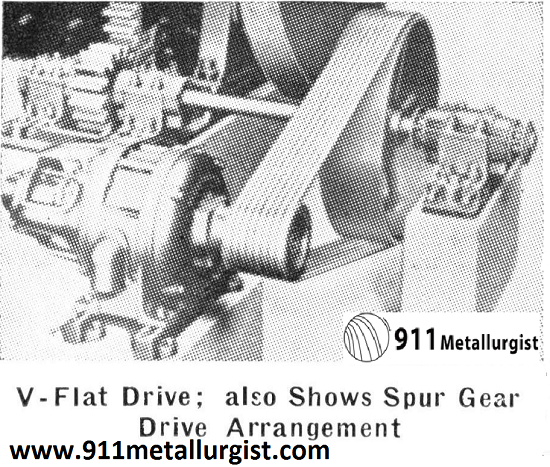
V-TO-FLAT Belt Drives transmit power from grooved driver sheaves to flat-face pulleys or to flywheels. This adoption of the V-belt drive is commonly found in plants making a gradual changeover from flat belts to the multiple V-belt drives. The chief advantage of the V-to- flat belt drive is low initial cost. However, they are limited to drives where the speed ratio is over 3 to 1 and where center distance is less than diameter of large sheave.
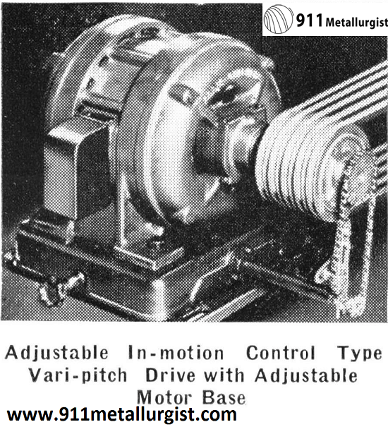
Adjustable Speed V-Belt Drives consist of one or both sheaves arranged to permit adjustment of the grooves, thus providing a larger or smaller diameter, resulting in an increase or decrease in speed of the driven shaft. The one- or two-groove adjustable-pitch diameter sheaves in combination with light-duty cast iron standard sheaves provide up to 50% speed range by a simple micrometer arrangement, and will transmit up to 4 horsepower. On 1- to 300-horsepower drives, vari-pitch sheaves can be obtained in two types: adjustable in motion or stationary; they require “companion” sheaves grooved to match vari-pitch groove spacing, and it is possible to obtain 9% to 28% speed variations. The adjustable In-Motion Control Vari-Pitch Sheave is used when speed changes are frequent and when adjustment is to be made while the sheave is in motion. A special motor base which moves on ball-bearings provides and maintains. uniform belt tension throughout the speed adjustment range. A handwheel located in the motor base increases or decreases the pitch diameter of the vari-pitch sheave, thereby varying the speed and simultaneously maintaining the proper belt tension by compensating for change in center distance. The Stationary Control Type Vari-Pitch Sheave is used when speed changes are infrequent and may only be made while the drive is stationary. By merely stopping the motor, releasing the belt tension, adjusting the pitch diameter, and restoring tension, the change is completed.
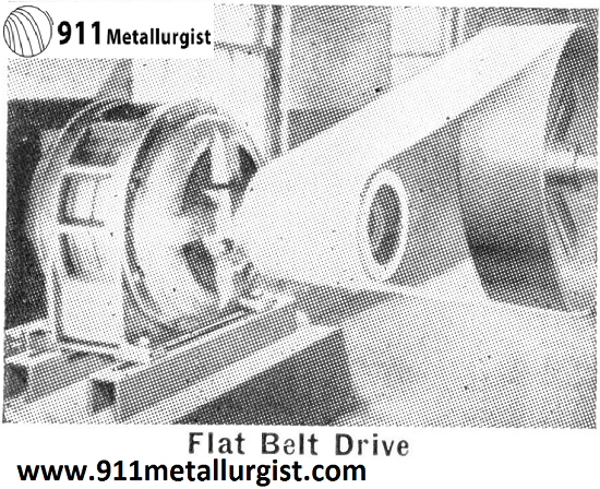
FLAT-BELT Drives may be used for transmitting power where the center distances of the pulleys are of considerable length. This type of drive receives considerable favor for group drives; that is, where a number of machines located adjacent to one another are so arranged that the group can be driven from one line- shaft and therefore from one source of power. The driving power is produced by a diesel or gasoline engine, waterwheel, steam engine turbine or electric motor. Due to the diversity of loads, the combined horsepower required to drive a group of machines is usually one-half to two-thirds of that required if each of the machines are individually driven. Rubber belts made of cotton duck and special compound of rubber are best used where the atmospheric conditions are damp or dusty.
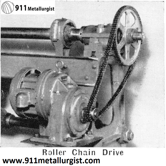
ROLLER Chain Drives are especially applicable when the distance between the driving and driven shafts is too short for belting and too long for gearing. The roller chain drive is positive, compact, and without the initial tension required for a V-belt or flat-belt drive. The initial cost is somewhat higher than the belt drive, but this is offset by greater efficiency, non¬slip, and obtaining a uniform turning movement. They have particular application on slow-speed drives, especially when motorized speed reducers are used.
More complete information can be obtained by writing any Equipment Company office.
SILENT Chain Drives are used for high speed power transmission up to 2000 horsepower. They have been used successfully on thousands of installations, and many of them have operated efficiently for 10, 20, and even 30 years. Due to positive tooth-to-tooth action they transmit full speed and power of the prime mover. There is no slippage as with belts. Their long wearing life with low upkeep expense make them desirable for many drive installations.
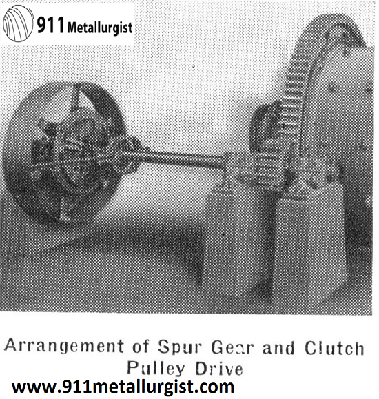
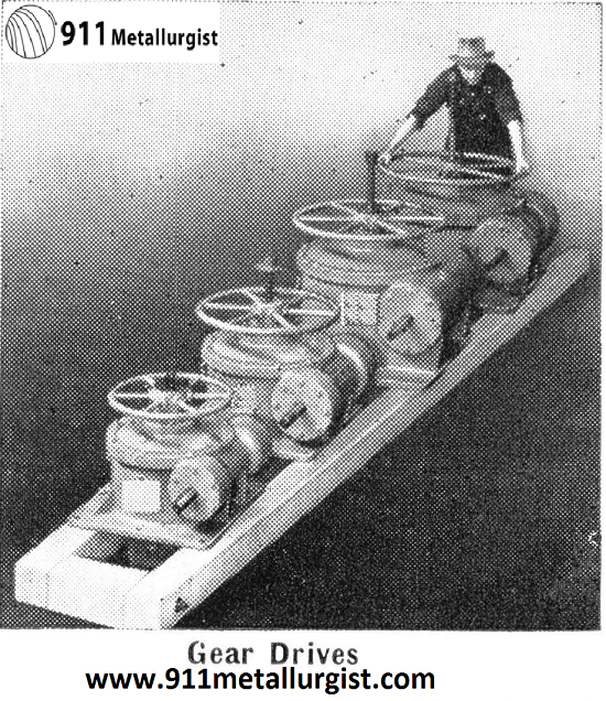
GEAR Drives are important elements of machines for transmitting power positively from one shaft to another shaft with the minimum of shaft centers. Spur, helical, and herringbone gears operate with parallel shafts; miter, bevel, worm and helical gears operate with their shafts at right angles to each other; and bevel and spiral gears may operate with their axis at an angle other than 90°.
For transmitting moderate loads with low-rim velocities cast-tooth gears are satisfactory; however, with high loads to be transmitted and high rim velocities, cut-tooth gears are recommended. Helical, spiral, and herringbone gears are always made with cut teeth. Spur gears are usually cut with 14½° pressure angle. Gears with teeth cut with 20° pressure angle are stronger and are used especially where pinions with a small number of teeth are required. The usual speed ratios range from 1:1 to approximately the following for various types of gears: Spur, 10:1; helical, 10:1; herringbone, 10:1; miter, 1:1; bevel, 6:1; worm 160:1. Where noise is objectionable, it is advisable to use rawhide, bakelite, or some approved type of non-metallic gear in conjunction with mating gear made of metal.
SPEED Reducers employ all the various types of gear drives described in the preceding paragraph. The gears are enclosed in a metal case which excludes water and dirt from the gears and which also provides an oil reservoir for supplying the gears with a continuous bath of lubricant. Speed reducers are used on many Equipment Company products such as side and center air-lift agitators, repulpers and scrubbers.
More complete information can be obtained by writing any Equipment Company office.
Information Required: Our Engineering Department will gladly assist you. Send in the following information:
- Horsepower and type of motor, or other power source.
- What is the name of machinery driven?
- Running H.P., starting H.P., peak H.P.
- Describe load conditions; uniformity, shock, reversal.
- Service conditions: temporary, intermittent, continuous.
- Atmosphere: dampness, water, acid, oil, dust, temperature.
- Shaft speeds and diameters.
- Direction of rotation of shafts.
- Which shaft is the driver?
- Horizontal distance between shafts.
- Vertical distance of shafts above floor.
- Distance to walls, ceilings, bearings, etc., which limit pulley, sheave, sprocket, or gear diameters, or belt widths.
- Pulley diameter and width of face on equipment in use.
- Is belt to be endless or to have fasteners?
- Desired pulley, sheave, sprocket or gear centers.
Source: This article is a reproduction of an excerpt of “In the Public Domain” documents held in 911Metallurgy Corp’s private library.
