Belt conveyors have proven themselves for many years as a dependable and low cost method of handling bulk materials at high flow rates. The success of a belt conveyor system greatly depends on the initial loading of the material on the belt. If the material is loaded on the belt at the center, at approximately the same speed and with minimum impact, then most of all belt conveyor problems disappear. Proper belt loading is primarily determined by the engineering and design of the conveyor transfer point.
General Design Considerations
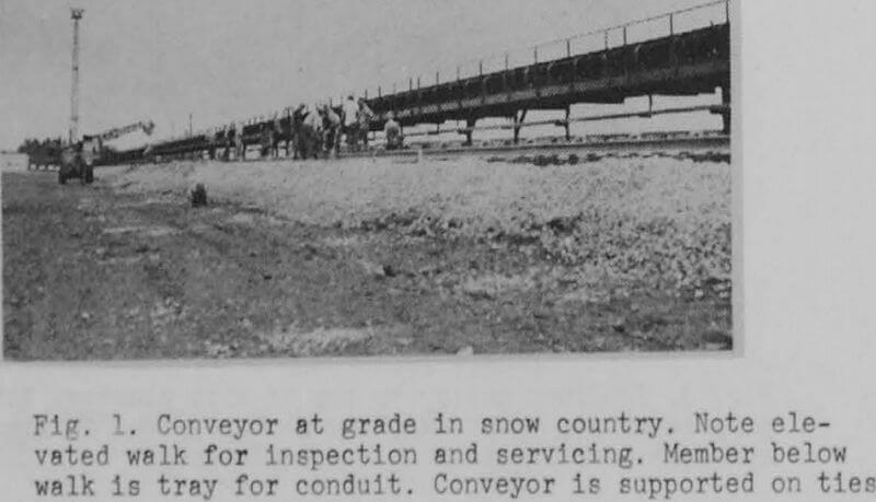
In the preliminary study of a material handling system involving belt conveyors, the number of belt transfer points should be reduced to a minimum in order to reduce degradation, dust and cost. All belt lines are to be elevated a few feet above ground to facilitate inspection, maintenance and cleanup. Railroad and plant roadway clearances for cranes and other mobile equipment, also for fire control must be considered, along with all contemplated future extensions. Initially about a 10 foot vertical distance should be allowed between working points of belts at transfer points. If of sufficient importance, a small scale model of the facility might be considered.
Proceeding further, the width and speed of conveyors for desired capacity, pulley diameters’, drives and motors, take-ups, etc. shall be calculated using accepted formulae found in catalogs and handbooks. All of this would be governed by operating experience. Some operators prefer to use 35° idlers only to minimize spill, while still using the standard 20° idlers for figuring capacity. Lagging of head pulley, if it is the driver, is considered good practice, with resultant saving in belt design. Drives should be direct connected where possible. It is assumed that any tramp iron has been removed prior to the transfer point, and therefore no magnetic protection is required. The number of various pulley sizes is to be kept to a minimum.
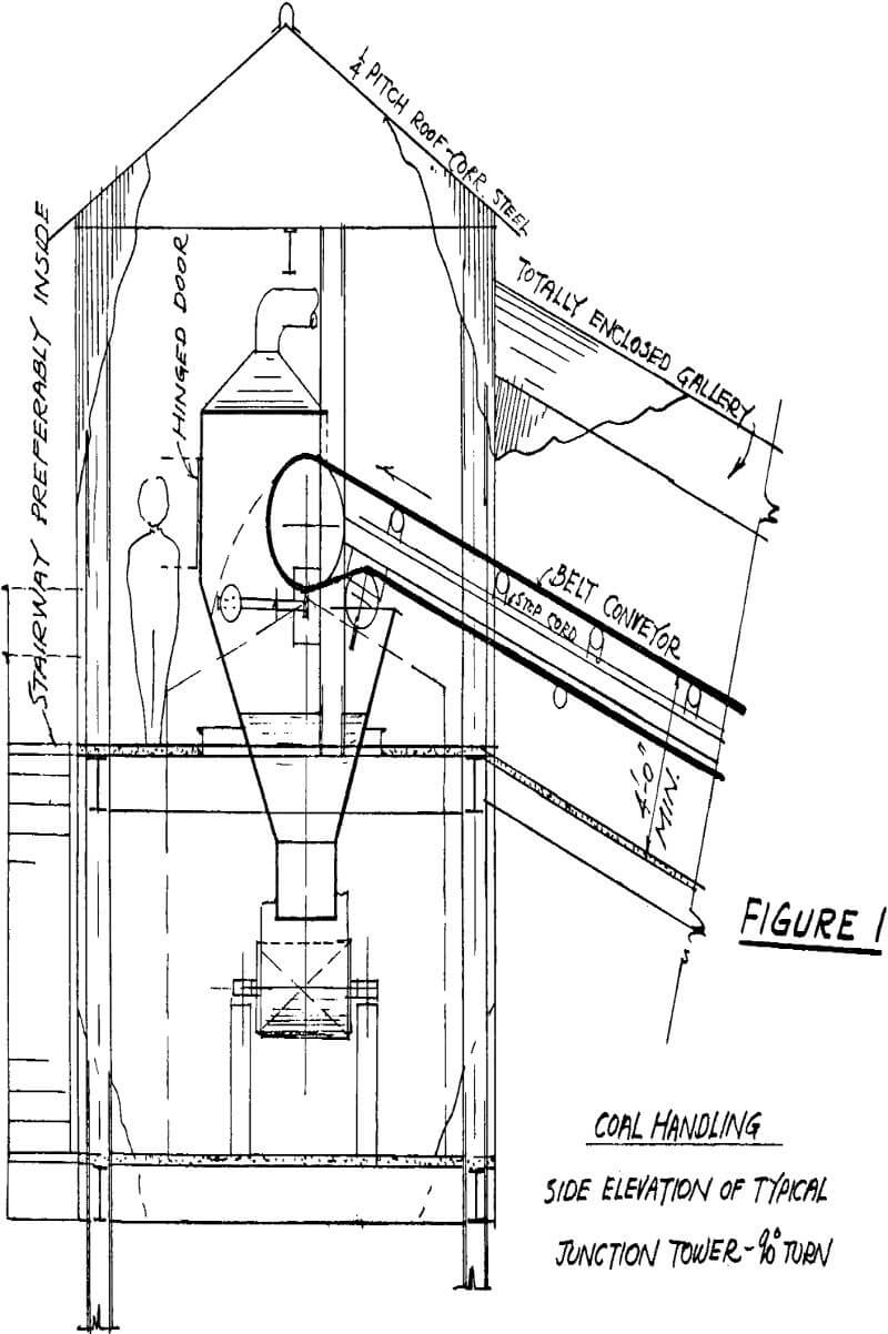
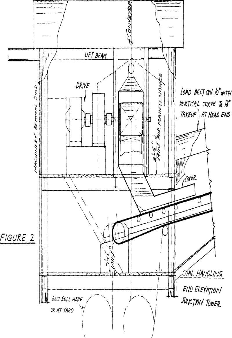
With the double-back chute design shown, the impact of material can be taken by steel plate for finer material, or by the so-called “stone box” for lumps. There is quite a controversy in the industry regarding the double-back chute design. The main selling point is that the back, slope of the chute is located far enough under the conveyor to catch most of the dribble-spill and minimize cleanup. The disadvantage of this design is that degradation of friable materials will be greater. It will depend on each specific operation which criterium is the determining factor.
Conveyor Discharge and Impact
Materials carried by a belt conveyor can be discharged from the belt in different ways to effect certain desired results. The simplest discharge from a conveyor belt is to let the material pass over a terminal pulley.
In most conveyor installations, the troughed belt goes through a transition section onto a flat pulley. The time required must be short enough to prevent the material, originally contained in the trough from spilling over the edges of a flat belt. The transition period should not exceed one second. Especially with free flowing materials like iron ore pellets, the belt speed should be at least 500 fpm to minimize spillage along the side of the head pulley.
In order to determine the point of impact at the loading point of the belt, the trajectory of the material from the head pulley must be established. As shown in figure 4 the material will leave the pulley at a point where the centrifugal force equals the gravity force, or Wm . cos r = Wm . V²/g . r The value of the term V²/g . r can be easily calculated and the initial point of tangency determined. Once this point is established, the trajectory of the discharged material can be plotted. The graphical method can be found in CEMA handbook “Belt Conveyors for Bulk Materials”.
Loading Chutes
Probably the most important feature at the transfer point is the “Chute”, on which the design is often subject to much controversy. The function of a chute is to transfer material in such a manner that breakage will be minimized for friable material, and that the material will flow in unison with the delivery and without plugging. The fines or scrapings from any cleaning device should be confined within the chute and this also applies to any snub pulley if possible.
Minimum working clearances for various materials passing through the chute are largely a matter of judgment. Thickness of steel in chutes is usually decided by first cost, competition or Purchaser, also the liners.
Flat valleys should be avoided as they tend to slow the flow. Some operators feel that stainless steel liners improve the flow angles by at least 5 degrees in addition to providing a cleaner surface. 5/16″ thick carbon steel is considered good practice for R.O.M. coal, with liners if desired. Suitable inspection doors should be included, at least 18″ square and preferably hinged.
Skirt Boards
To retain the material on the belt, while it is accelerating after leaving the loading point, skirt boards are generally required. These skirt boards usually are an extension of the sides of the loading chutes and extend parallel to one another for some distance along the belt.
Skirt boards should generally follow the accepted rule of inside-width equal to 2/3 of belt width. They should be as short as possible but long enough to settle the material on belt, and designed to relieve the gap between them and belt both vertically and horizontally. The bottom of skirtboards should be equipped with a flexible sealing device to prevent belt damage, and readily adjustable for wear. Abrasive liners are required when handling such material. There are innumerable designs of belt sealing devices, most of which have been made by master mechanics on the job after altering original equipment. Consider bolted cover over skirt boards if dictated by nature of material handled and degree of dust control.
Belt Conveyor Structures
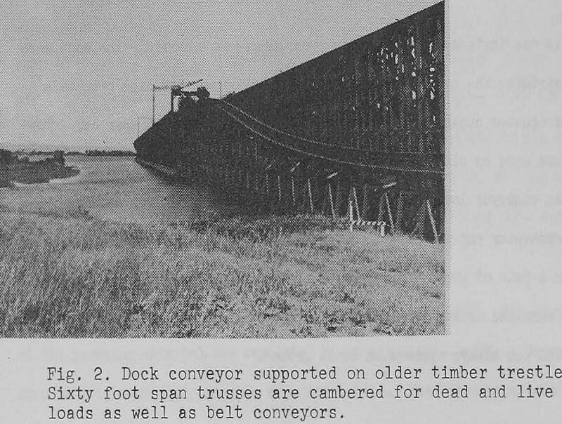
It is axiomatic that in designing a bulk material handling system the primary consideration is the functioning of the machines. The structure is secondary its reasons for being are to support, enclose and provide access to the machine, for servicing. This results in a wide variety of supporting structures. Other considerations are: plant layout, local soil conditions, climate, local laws and codes, and last, but by no means least, the Customer’s wishes.
Nearly all of our steel is shop welded and field bolted using high strength bolts. We normally shop assemble the work into the largest pieces which can be economically shipped and handled in the field. Structural grade steel, ASTM A-36 is used for most work although we have used ASTM A-242 for corrosion resistance and alloy steels for reduction in dead weight.
Loading conditions vary from job to job but the following must be considered:
- Dead load, which includes the structure itself, the mechanical components, belt, idlers, pulleys, drive, limit switches, wiring, etc.
- Earthquake forces according to seismic zone.
- Snow load according to geographical area.
- Belt pull during starting, stopping or running. Accelerating or decelerating will be governed by electrical controls or allowable belt tensions, and so varies from job to job.
- Live load due to material on the belt.
- Live load on walkways. Normally taken at one hundred pounds per square foot locally but twenty five pounds per square foot for the span.
- Wind in any direction. The wind loads are as given in American National Standards Institute, “Minimum Design Loads in Buildings and Other Structures”.
- No allowance is made for impact due to the bouncing of lumps as they move along the belt.
For dusty materials hoods may be employed to contain the dust. They are normally semi-circular and rest on the stringers or on brackets which are attached to the stringers. They are usually hinged on the side opposite the walkway and can be raised in short sections for inspection or servicing. Hoods are likely to be made of corrugated galvanized steel or aluminum. Some hoods may be shaped differently. For example: some may be a circular arc above the belt with both sides open, some may have a vertical side with a circular arc over the belt and one side open.
Belts exposed to the wind may lift off the idlers and conceivably endanger an expensive belt or personnel. Where there is no hood to prevent this a semi-circular hoop is used to limit the amount of uplift and shorten the distance – between node points. Where the material is dusty and there is a tripper or other machine which does not permit the use of hoods, wind guards are used. These are generally sheet metal plates extending two inches above the top of the belt, flanged at the top for stiffness and bolted to the stringers. They are used on the side from which the prevailing wind comes or, better still, on both sides.
Foundations for conveyors are as varied as are the local conditions, running the gamut from timber ties on ballast to deep piled foundations. They are treated just as foundations for any other project. Normally the vertical loads are comparatively light and the foundation design is likely to be governed by uplift or lateral loads.
Belt conveyors are often a major component of large material handling machines and the structure for these range from very simple fixed tripper frames to extremely complicated structures. For example, a stacker-reclaimer tows a tripper trailer which operates in two positions. For stacking, the tripper boom is raised and the material passes from the yard belt over the tripper, through a chute to the stacker boom and thence to the stockpile. When the tripper boom is in its lower position the distance from the tripper to the stacker is increased by some twenty seven feet, allowing the head pulley to clear the stacker chute and be lowered to a by pass chute. This permits incoming material on the yard belt to by pass the stacker boom, drop back onto the yard belt and continue on to the dock. Alternately material from the stock pile can be placed in a chute at the outer end of the lowered stacker boom. The belt is reversed and material flows back over the tail pulley and onto the yard belt.
The portable hopper had a capacity of 1000 tons “as filled”. The trajectory of the incoming material was regulated by an adjustable baffle. There were four outlets each equipped with a quadrant gate. The gates were located so that two bottom dump trucks could drive under the hopper simultaneously. One truck was loaded while the adjoining aisle was being cleared and a new truck taking position.