In all ore dressing and milling Operations, including flotation, cyanidation, gravity concentration, and amalgamation, the Working Principle is to crush and grind, often with rod mill or ball mill, the ore in order to liberate the minerals. In the chemical and process industries, grinding is an important step in preparing raw materials for subsequent treatment. In present-day practice, the ore is reduced to a size many times finer than can be obtained with crushers. Over a period of many years, various fine grinding mills have been developed and used, but the ball mill has become standard due to its simplicity and low operating cost.
A ball mill efficiently operated performs a wide variety of services. In small milling plants, where simplicity is most essential, it is not economical to use more than single stage crushing, because the Steel-Head Ball or Rod Mill will take up to 2″ feed and grind it to the desired fineness. In larger plants where several stages of coarse and fine crushing are used, it is customary to crush from 1/2″ to as fine as 8 mesh.
Many grinding circuits necessitate the regrinding of concentrates or middling products to extremely fine sizes to liberate the closely associated minerals from each other. In these cases, the feed to the ball mill may be from 10 to 100 mesh or even finer. Here this Ball Mill Design Calculator.

Where the finished product does not have to be uniform, a ball mill may be operated in open circuit, but where the finished product must be uniform it is essential that the grinding mill be used in closed circuit with a screen, if a coarse product is desired, and with a classifier if a fine product is required. In most cases it is desirable to operate the grinding mill in closed circuit with a screen or classifier as higher efficiency and capacity are obtained. Often a mill using steel rods as the grinding medium is recommended, where the product must have the minimum amount of fines (rods give a more nearly uniform product).
Often a problem requires some study to determine the economic fineness to which a product can or should be ground. In this case the 911Equipment Company offers its complete testing service so that accurate grinding mill size may be determined.
Ball Mill Capacity VS Rod Mill Capacity
Until recently many operators have believed that one particular type of grinding mill had greater efficiency and resulting capacity than some other type. However, it is now commonly agreed and accepted that the work done by any ball mill depends directly upon the power input; the maximum power input into any ball or rod mill depends upon weight of grinding charge, mill speed, and liner design.
Working Principle & Operation
The apparent difference in capacities between grinding mills (listed as being the same size) is due to the fact that there is no uniform method of designating the size of a mill, for example: a 5′ x 5′ Ball Mill has a working diameter of 5′ inside the liners and has 20 per cent more capacity than all other ball mills designated as 5′ x 5′ where the shell is 5′ inside diameter and the working diameter is only 4’8″ with the liners in place.
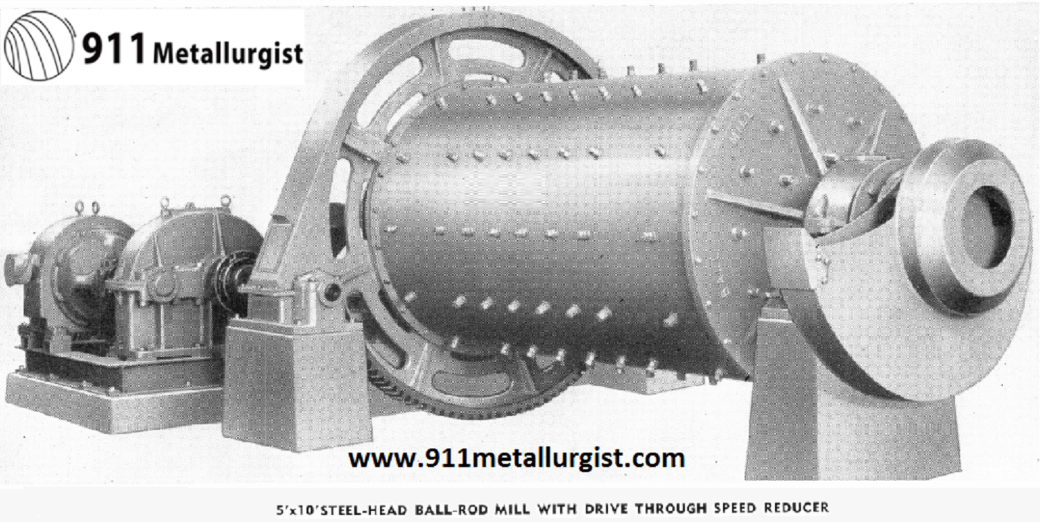
Ball-Rod Mills, based on 4″ liners and capacity varying as 2.6 power of mill diameter, on the 5′ size give 20 per cent increased capacity; on the 4′ size, 25 per cent; and on the 3′ size, 28 per cent. This fact should be carefully kept in mind when determining the capacity of a Steel- Head Ball-Rod Mill, as this unit can carry a greater ball or rod charge and has potentially higher capacity in a given size when the full ball or rod charge is carried.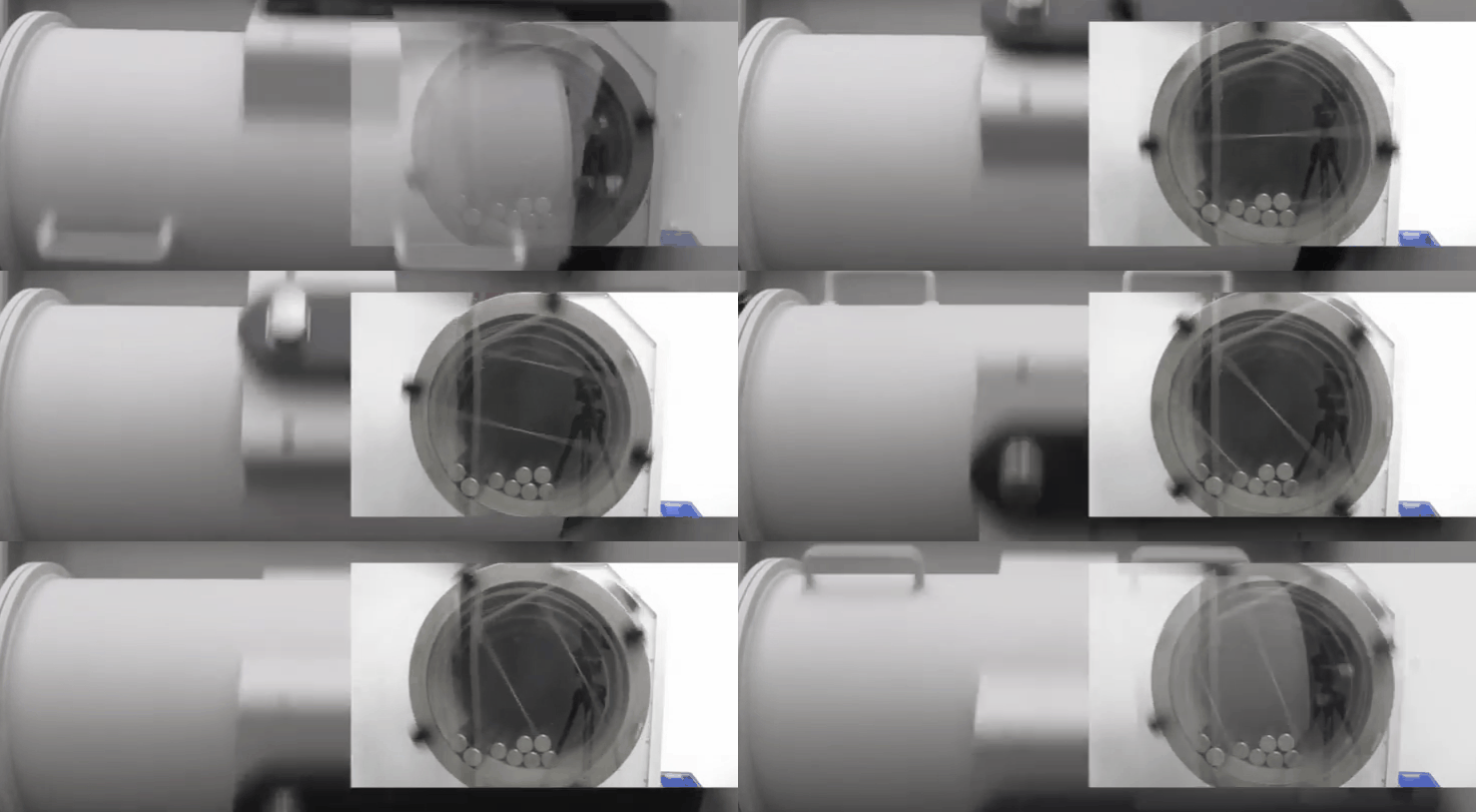
A mill shorter in length may be used if the grinding problem indicates a definite power input. This allows the alternative of greater capacity at a later date or a considerable saving in first cost with a shorter mill, if reserve capacity is not desired.
The capacities of Ball-Rod Mills are considerably higher than many other types because the diameters are measured inside the liners.
In Table I capacities have been calculated according to the conditions specified.
A grate discharge may give beneficial results on certain ores especially where an excess of fine sizes is detrimental.
Rod Mill Capacity Table
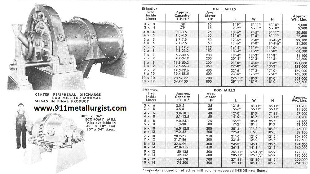
Small Ball Mill Capacity and Sizing
Ball VS Rod Mill Conversion
The correct grinding mill depends so much upon the particular ore being treated and the product desired, that a mill must have maximum flexibility in length, type of grinding medium, type of discharge, and speed. With the Ball-Rod Mill it is possible to build this unit in exact accordance with your requirements, as illustrated.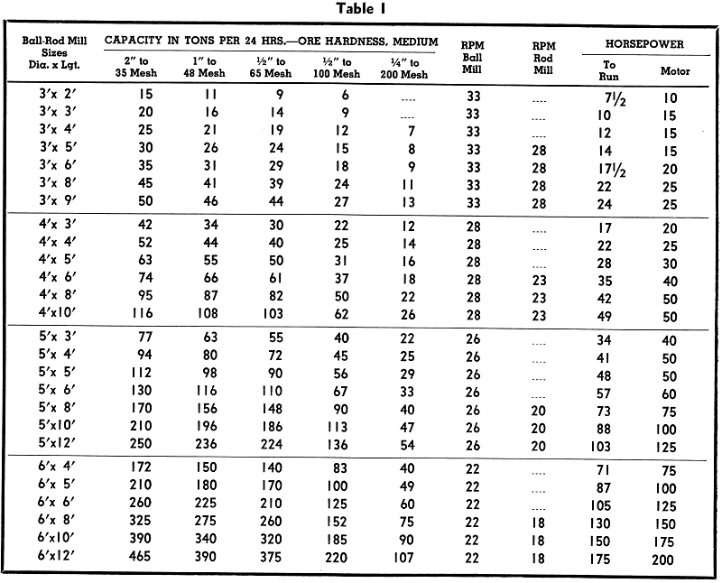
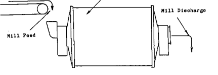
Types of Mill Discharge
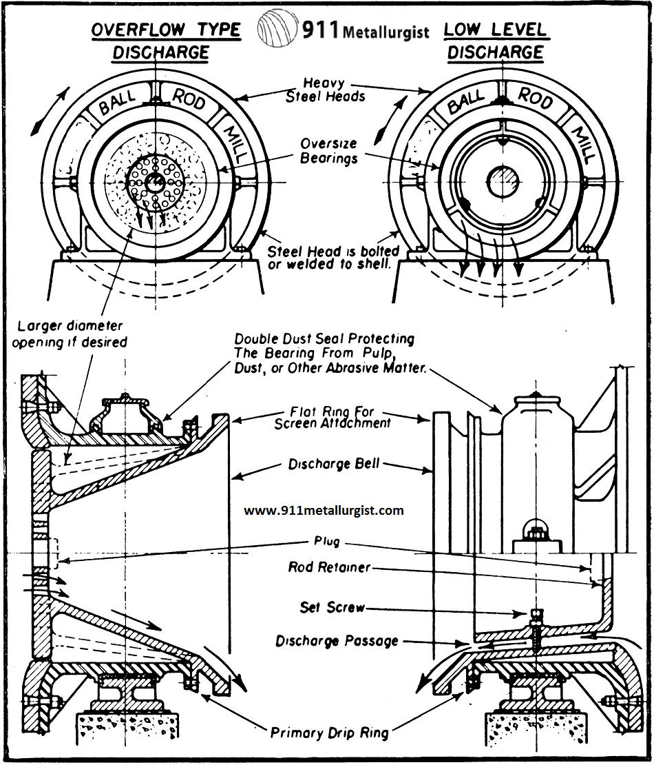
Steel-Head Ball-Rod Mills are available in any one of five different types of discharge:
- Overflow,
- perforated overflow,
- return spiral,
- grate, and
- peripheral.
To best serve your needs, the Trunnion can be furnished with small (standard), medium, or large diameter opening for each type of discharge. The sketch shows diagrammatic arrangements of the four different types of discharge for each size of trunnion opening, and peripheral discharge is described later.
Ball Mill Trunnion and Mill Grate Discharge
The overflow type is more commonly used as it is lower in first cost. These mills have large trunnion openings which allow high circulating loads to be carried if desired.
Any overflow type mill can be easily converted to a grate discharge type by merely adding the improved grate head liners and the proper shell liners, or vice versa.
Ball-Rod Mills of the grate discharge type are made by adding the improved type of grates to a standard Ball-Rod Mill. These grates are bolted to the discharge head in much the same manner as the standard headliners.
The grates are of alloy steel and are cast integral with the lifter bars which are essential to the efficient operation of this type of ball or rod mill. These lifter bars have a similar action to a pump: i. e., in lifting the product so as to discharge quickly through the mill trunnion.
These Discharge Grates also incorporate as an integral part, a liner between the lifters and steel head of the ball mill to prevent wear of the mill head. By combining these parts into a single casting, repairs and maintenance are greatly simplified. The center of the grate discharge end of this mill is open to permit adding of balls or for adding water to the mill through the discharge end.
Instead of being constructed of bars cast into a frame, Grates are cast entire and have cored holes which widen toward the outside of the mill similar to the taper in grizzly bars. The grate type discharge is illustrated.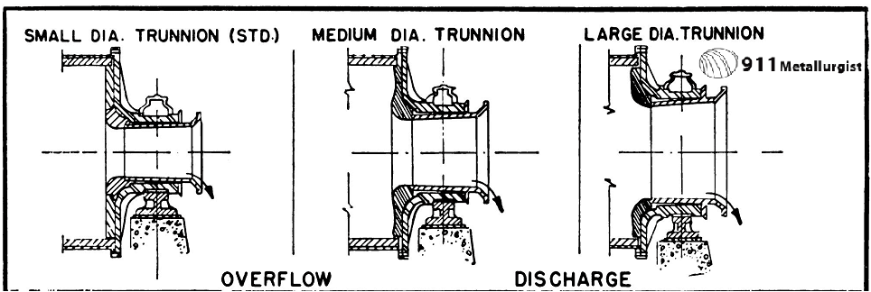


Peripheral Grinding Mill Discharge
The peripheral discharge type of Ball-Rod Mill is a modification of the grate type, and is recommended where a free gravity discharge is desired. It is particularly applicable when production of too many fine particles is detrimental and a quick pass through the mill is desired, and for dry grinding.
The drawings show the arrangement of the peripheral discharge. The discharge consists of openings in the shell into which bushings with holes of the desired size are inserted. On the outside of the mill, flanges are used to attach a stationary discharge hopper to prevent pulp splash or too much dust.
The mill may be operated either as a peripheral discharge or a combination or peripheral and trunnion discharge unit, depending on the desired operating conditions. If at any time the peripheral discharge is undesirable, plugs inserted into the bushings will convert the mill to a trunnion discharge type mill.

Load Capacity of Trunnion Bearings
are made to support a mill with a length double its diameter


Ball Mill & Rod Mill Liners
The head and shell liners for Ball-Rod Mills can be furnished of:
- Decolloy,
- Hard White Iron,
- Electric Steel,
- Chrome-Moly Steel,
- Manganese Steel.
These liners are all of ample thickness to give long life and uniform wear, yet, when new, they do not unduly decrease the capacity of the ball mill.
What is Decolloy? Decolloy is one of the hardest and toughest white cast iron compositions commercially available. It is essentially a high carbon base chrome and nickel iron.
Unless otherwise specified, a hard iron liner is furnished. This liner is made of the best grade white iron and is most serviceable for the smaller size mills where large balls are not used. Hard iron liners have a much lower first cost.
Electric steel, although more expensive than hard iron, has advantage of minimum breakage and allows final wear to thinner section. Steel liners are recommended when the mills are for export or where the source of liner replacement is at a considerable distance.
Molychrome steel has longer wearing qualities and greater strength than hard iron. Breakage is not so apt to occur during shipment, and any size ball can be charged into a mill equipped with molychrome liners.
Manganese liners for Ball-Rod Mills are the world famous AMSCO Brand, and are the best obtainable. The first cost is the highest, but in most cases the cost per ton of ore ground is the lowest. These liners contain 12 to 14% manganese.
The feed and discharge trunnions are provided with cast iron or white iron throat liners. As these parts are not subjected to impact and must only withstand abrasion, alloys are not commonly used but can be supplied.
Liners for any size mill are of such dimensions and weight that they will pass through the manhole without difficulty.
Grinding Mill Gears
Gears for Ball-Rod Mills drives are furnished as standard on the discharge end of the mill where they are out of the way of the classifier return, scoop feeder, or original feed. Due to convertible type construction the mills can be furnished with gears on the feed end. Gear drives are available in two alternative combinations, which are:
- Cast Tooth Spur Gear and Pinion. These gears are made of high grade cast iron with cast teeth which are made from a full pattern and not a sweep pattern. This insures round gears which run true and accurately. The pinion is made of cast electric steel with correctly formed teeth; cut steel pinion can be supplied.
- Cut Tooth Spur Gear and Pinion. The gear is made of high grade cast iron with teeth accurately machine cut from the blank; the pinion is a steel forging with precision machine cut teeth.
The gears are provided with a substantial web centrally placed, machined on both faces and drilled to template so that if the gear is worn on one side, it can be reversed, as both sides are machined.
All pinions are properly bored, key-seated, and pressed onto the steel countershaft, which is oversize and properly keyseated for the pinion and drive pulleys or sheaves. The countershaft operates on high grade, heavy duty, nickel babbitt bearings.
The three point bearing pinion shaft insures perfect alignment, and longer, more dependable life. Shaft and bearings are heavy and of ample size; bearings are hooded to exclude dirt.
The bearings are mounted on heavy sole plates which give perfect alignment. These sole plates are provided with take-ups for easy and quick adjustment.
Grinding Mill Drives
Any type of drive can be furnished for Ball-Rod Mills in accordance with your requirements. Belt drives are available with pulleys either plain or equipped with friction clutch. Various V- Rope combinations can also be supplied.
When a motor drive is selected, please mention which drive arrangement is to be used.
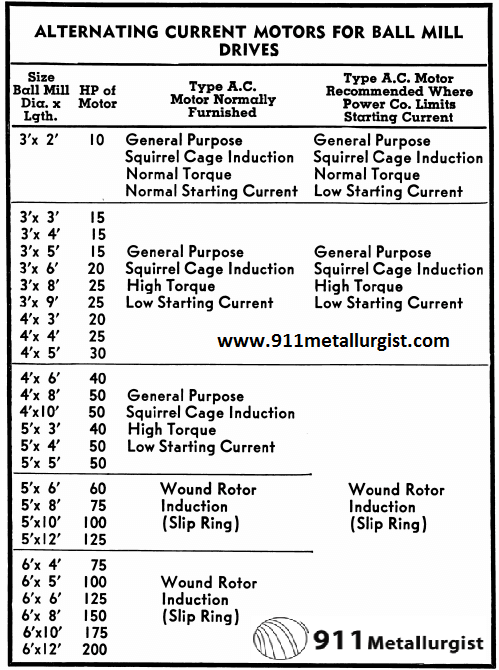
The most economical drive to use up to 50 H. P., is a high starting torque motor connected to the pinion shaft by means of a flat or V-Rope drive. For larger size motors the wound rotor (slip ring) is recommended due to its low current requirement in starting up the ball mill.
Should you be operating your own power plant or have D. C. current, please specify so that there will be no confusion as to motor characteristics. If switches are to be supplied, exact voltage to be used should be given.
Ball Mill Grinding Circuit
Even though many ores require fine grinding for maximum recovery, most ores liberate a large percentage of the minerals during the first pass through the grinding unit. Thus, if the free minerals can be immediately removed from the ball mill classifier circuit, there is little chance for overgrinding.
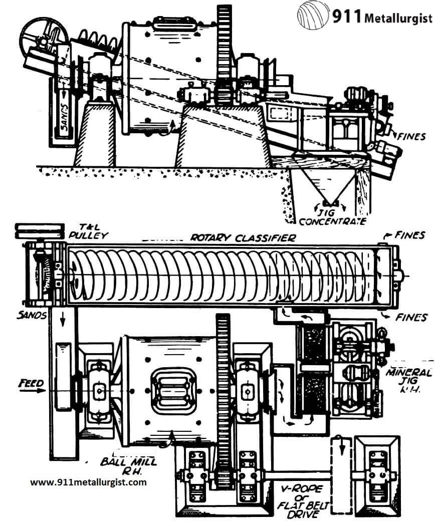
This is actually what has happened wherever Mineral Jigs or Unit Flotation Cells have been installed in the ball mill classifier circuit. With the installation of one or both of these machines between the ball mill and classifier, as high as 70 per cent of the free gold and sulphide minerals can be immediately removed, thus reducing grinding costs and improving over-all recovery.
The advantage of this method lies in the fact that heavy and usually valuable minerals, which otherwise would be ground finer because of their faster settling in the classifier and consequent return to the grinding mill, are removed from the circuit as soon as freed. This applies particularly to gold and lead ores.

The Mineral Jig is a high speed fine mineral recovery unit and is distinctive in that it does not dilute the circuit; minimum water is used due to synchronization of the valve with plunger stroke.
The “Sub-A” Unit Flotation Cell has the exclusive gravity flow principle of circulating coarse material, which has made it possible to use flotation of a ball mill discharge without chokeups.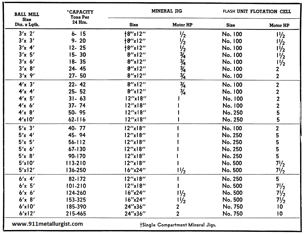
Ball Mill Specifications
All-Steel Shells and Heads
Ball-Rod Mills have heavy rolled steel plate shells which are arc welded inside and outside to the steel heads or to rolled steel flanges, depending upon the type of mill. The double welding not only gives increased structural strength, but eliminates any possibility of leakage.
Where a single or double flanged shell is used, the faces are accurately machined and drilled to template to insure perfect fit and alignment with the holes in the head. These flanges are machined with male and female joints which take the shearing stresses off the bolts.
The Ball-Rod Mill Heads are oversize in section, heavily ribbed and are cast from electric furnace steel which has a strength of approximately four times that of cast iron. The head and trunnion bearings are designed to support a mill with length double its diameter. This extra strength, besides eliminating the possibility of head breakage or other structural failure (either while in transit or while in service), imparts to Ball-Rod Mills a flexibility heretofore lacking in grinding mills. Also, for instance, if you have a 5′ x 5′ mill, you can add another 5′ shell length and thus get double the original capacity; or any length required up to a maximum of 12′ total length.
On Type “A” mills the steel heads are double welded to the rolled steel shell. On type “B” and other flanged type mills the heads are machined with male and female joints to match the shell flanges, thus taking the shearing stresses from the heavy machine bolts which connect the shell flanges to the heads.
The manhole cover is protected from wear by heavy liners. An extended lip is provided for loosening the door with a crow-bar, and lifting handles are also provided. The manhole door is furnished with suitable gaskets to prevent leakage.
Trunnion Bearings of Grinding Mill
The trunnions are an integral part of the steel heads and are turned true with the axis of the mill. After machining, the trunnions are given a polished surface to minimize friction.
The mill trunnions are carried on heavy babbitt bearings which provide ample surface to insure low bearing pressure. If at any time the normal length is doubled to obtain increased capacity, these large trunnion bearings will easily support the additional load.
Trunnion bearings are of the rigid type, as the perfect alignment of the trunnion surface on Ball-Rod Mills eliminates any need for the more expensive self-aligning type of bearing.
The highest grade nickel babbitt obtainable is used in the trunnion bearings and pinion shaft bearings.
The cap on the upper half of the trunnion bearing is provided with a shroud which extends over the drip flange of the trunnion and effectively prevents the entrance of dirt or grit. The bearing has a large space for wool waste and lubricant and this is easily accessible through a large opening which is covered to prevent dirt from getting into the bearing. Ball and socket bearings can be furnished.
Types of Mill Feed Chute
Scoop Feeders for Ball-Rod Mills are made in various radius sizes. Standard scoops are made of cast iron and for the 3′ size a 13″ or 19″ feeder is supplied, for the 4′ size a 30″ or 36″, for the 5′ a 36″ or 42″, and for the 6′ a 42″ or 48″ feeder. Welded steel scoop feeders can, however, be supplied in any radius.
The correct size of feeder depends upon the size of the classifier, and the smallest feeder should be used which will permit gravity flow for closed circuit grinding between classifier and the ball or rod mill. All feeders are built with a removable wearing lip which can be easily replaced and are designed to give minimum scoop wear.
A combination drum and scoop feeder can be supplied if necessary. This feeder is made of heavy steel plate and strongly welded. These drum-scoop feeders are available in the same sizes as the cast iron feeders but can be built in any radius. Scoop liners can be furnished.
The trunnions on Ball-Rod Mills are flanged and carefully machined so that scoops are held in place by large machine bolts and not cap screws or stud bolts. The feed trunnion flange is machined with a shoulder for insuring a proper fit for the feed scoop, and the weight of the scoop is carried on this shoulder so that all strain is removed from the bolts which hold the scoop.
Steel Head Ball Mills

Steel-Head Rod Mills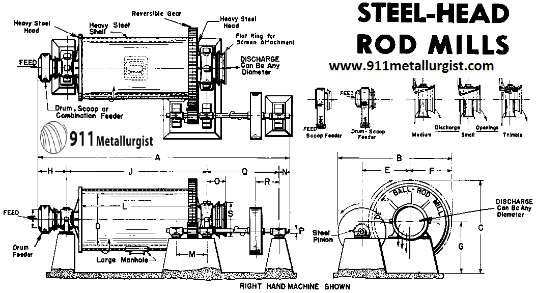
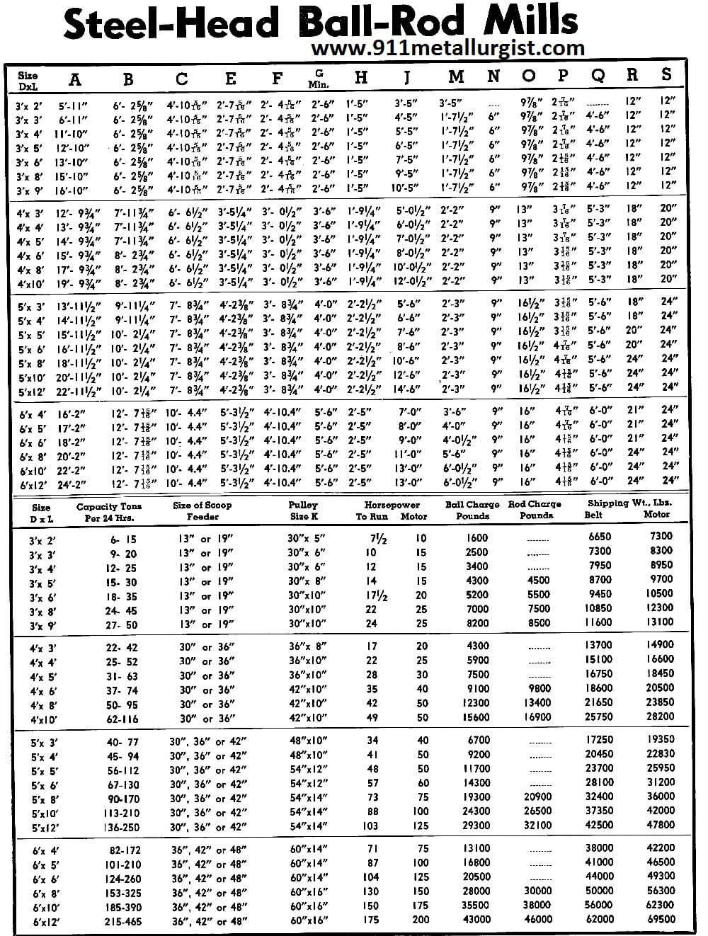
Quotation on a Ball Mill Price or a Rod Mill Price
When requesting a quotation on a Ball- Rod Mill, it is requested that you include the following information:
- Type of mill: Type “A” is standard, except 3′ x 2′ which is Type “B” without manhole.
- Discharge, whether overflow, perforated over-flow, return spiral, grate or peripheral discharge. The size of trunnion opening desired should be specified. Unless specified, the small diameter trunnion overflow type will be furnished.
- Liners—hard iron liners are standard and will be furnished unless otherwise specified.
- Gears—whether cast tooth spur gear and pinion (standard) or cut tooth spur gear and pinion.
- Drive—belt or motor. Belt drive without pulley is standard. If motor drive, specify type of motor and also type of drive arrangement.
- Feeders—cast iron scoop feeder with removeable wearing lip of alloy steel is standard; welded steel scoop can be supplied if desired. Drum-scoop feeder made of welded steel, is available. Specify size desired.
- When ordering, include a small sketch of your ball mill classifier layout. Right hand mill is standard. This should show the ball mill (feed, discharge and position of drive); Unit Flotation Cell or a Mineral Jig, if in circuit, and classifier.
Grinding Rods
High carbon steel rods are recommended, hot rolled, hot sawed or sheared, to a length of 2″ less than actual length of mill taken inside the liners.
The initial rod charge is generally a mixture ranging from 1.5″ to 3″ in diameter. During operation, rod make-up is generally the maximum size. The weights per lineal foot of rods of various diameters are approximately: 1.5″ to 6 lbs.; 2″-10.7 lbs.; 2.5″-16.7 lbs.; and 3″-24 lbs.
Grinding Balls
Forged from the best high carbon manganese steel, they are of the finest quality which can be produced and give long, satisfactory service.
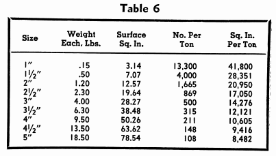
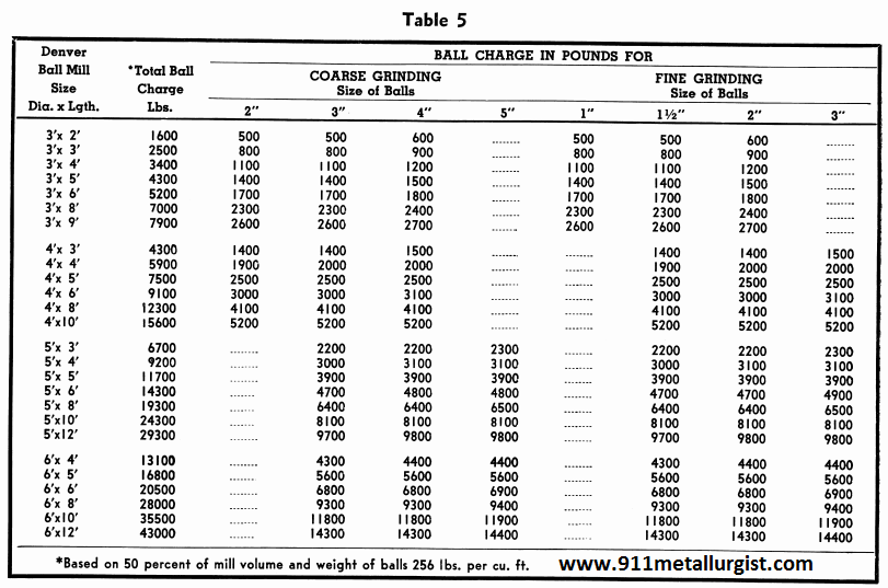
Data on ball charges for Ball-Rod Mills are listed in Table 5. Further information regarding grinding balls is included in Table 6.
What is the Steel Charge of a Ball Mill
Difference Between a Rod Mill and Ball Mill
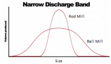
Rod Mills has a very define and narrow discharge product size range. Feeding a Rod Mill finer rocks will greatly impact its tonnage while not significantly affect its discharge product sizes. The 3.5” diameter rod of a mill, can only grind so fine.
 |
 |
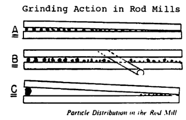
Crushers are well understood by most. Rod and Ball Mills not so much however as their size reduction actions are hidden in the tube (mill). As for Rod Mills, the image above best expresses what is going on inside. As rocks is feed into the mill, they are crushed (pinched) by the weight of its 3.5” x 16’ rods at one end while the smaller particles migrate towards the discharge end and get slightly abraded (as in a Ball Mill) on the way there.
How much steel enters a ball mill
Source: This article is a reproduction of an excerpt of “In the Public Domain” documents held in 911Metallurgy Corp’s private library.
Small Ball Mill FOR SALE
We have Small Ball Mills for sale coming in at very good prices. These ball mills are relatively small, bearing mounted on a steel frame. All ball mills are sold with motor, gears, steel liners and optional grinding media charge/load.
Ball Mills or Rod Mills in a complete range of sizes up to 10′ diameter x 20′ long, offer features of operation and convertibility to meet your exact needs. They may be used for pulverizing and either wet or dry grinding systems. Mills are available in both light-duty and heavy-duty construction to meet your specific requirements.
All Mills feature electric cast steel heads and heavy rolled steel plate shells. Self-aligning main trunnion bearings on large mills are sealed and internally flood-lubricated. Replaceable mill trunnions. Pinion shaft bearings are self-aligning, roller bearing type, enclosed in dust-tight carrier. Adjustable, single-unit soleplate under trunnion and drive pinions for perfect, permanent gear alignment.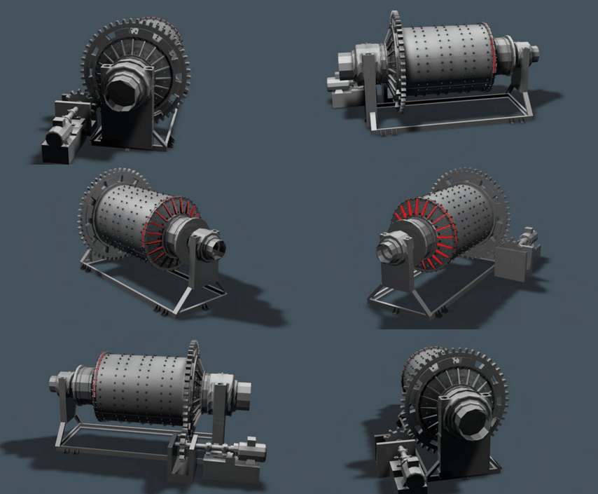
The Ball and Rod Mill size we specialize in are:
|
600 mm X 1200 mm [ 24″ X 48″] = [ 2′ X 4′] |
|
600 mm X 1800 mm [ 24″ X 72″] = [ 2′ X 6′] |
|
900 mm X 1800 mm [ 36″ X 72″] = [ 3′ X 6′] |
|
1200 mm X 2400 mm [ 48″ X 96″] = [ 4′ X 8′] |
|
1500 mm X 3000 mm [ 60″ X 120″] = [ 5′ X 10′] |
|
1500 mm X 3500 mm [ 60″ X 138″] = [ 5′ X 11.5′] |
|
1800 mm X 3000 mm [ 72″ X 120″] = [ 6′ X 10′] |
|
and up to 10′ x 12′ |
Choice of liners including ceramic, manganese, decolloy, alloy steel or steel plate in wide variety of types, including blade type liner for washing tenacious clay from the product.
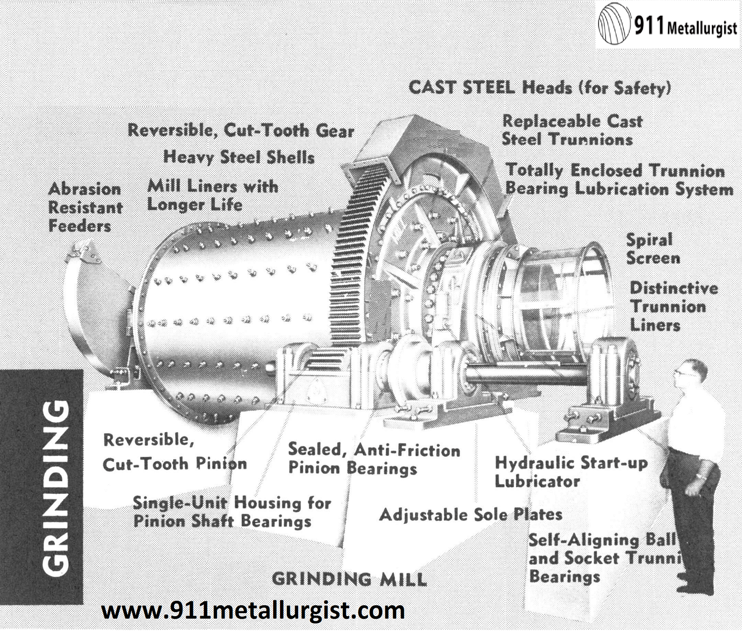

CERAMIC LINED BALL MILL
Ball Mills can be supplied with either ceramic or rubber linings for wet or dry grinding, for continuous or batch type operation, in sizes from 15″ x 21″ to 8′ x 12′. High density ceramic linings of uniform hardness male possible thinner linings and greater and more effective grinding volume. Mills are shipped with liners installed.
Ceramic linings are designed for close tolerance precision fit. Grinding media can be furnished as either flint pebbles or high density ceramic balls (3.4 sp. gr. same as ceramic lining brick).
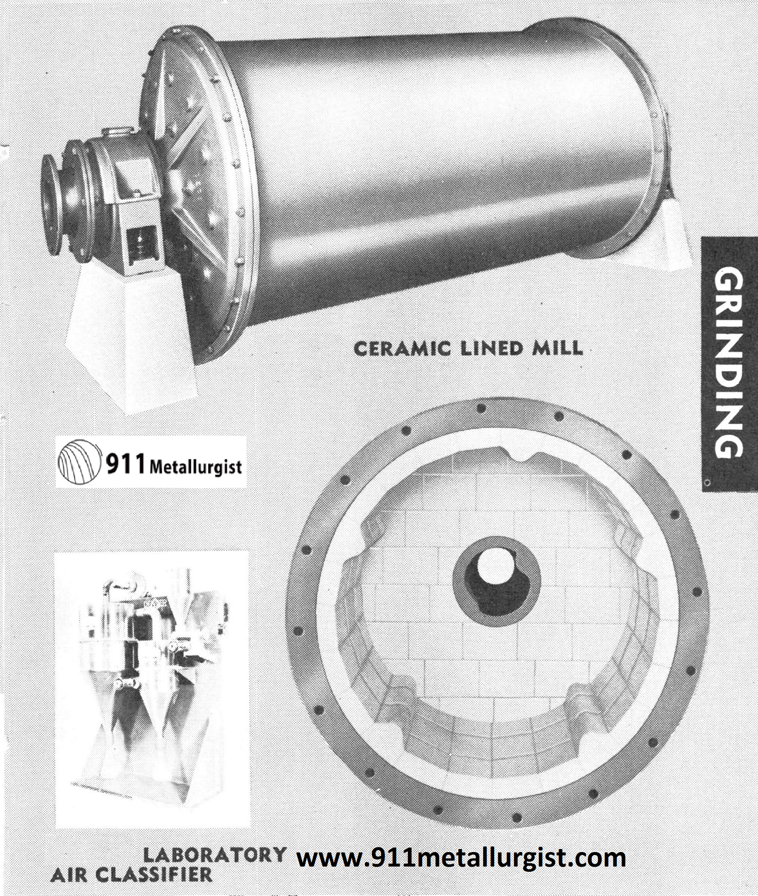
DRY GRINDING BALL MILL
Complete laboratory testing service, mill and air classifier engineering and proven equipment make possible a single source for your complete dry-grinding mill installation. Units available with air swept design and centrifugal classifiers or with elevators and mechanical type air classifiers. All sizes and capacities of units. Laboratory-size air classifier also available.

RAPID DISCHARGE GRINDING BALL MILL
High-capacity, low cost grinding, wet or dry. Simple, efficient, dependable; eliminate fines, slimes. Write for Bulletin.
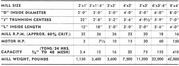
 RAPID-DISCHARGE MILL
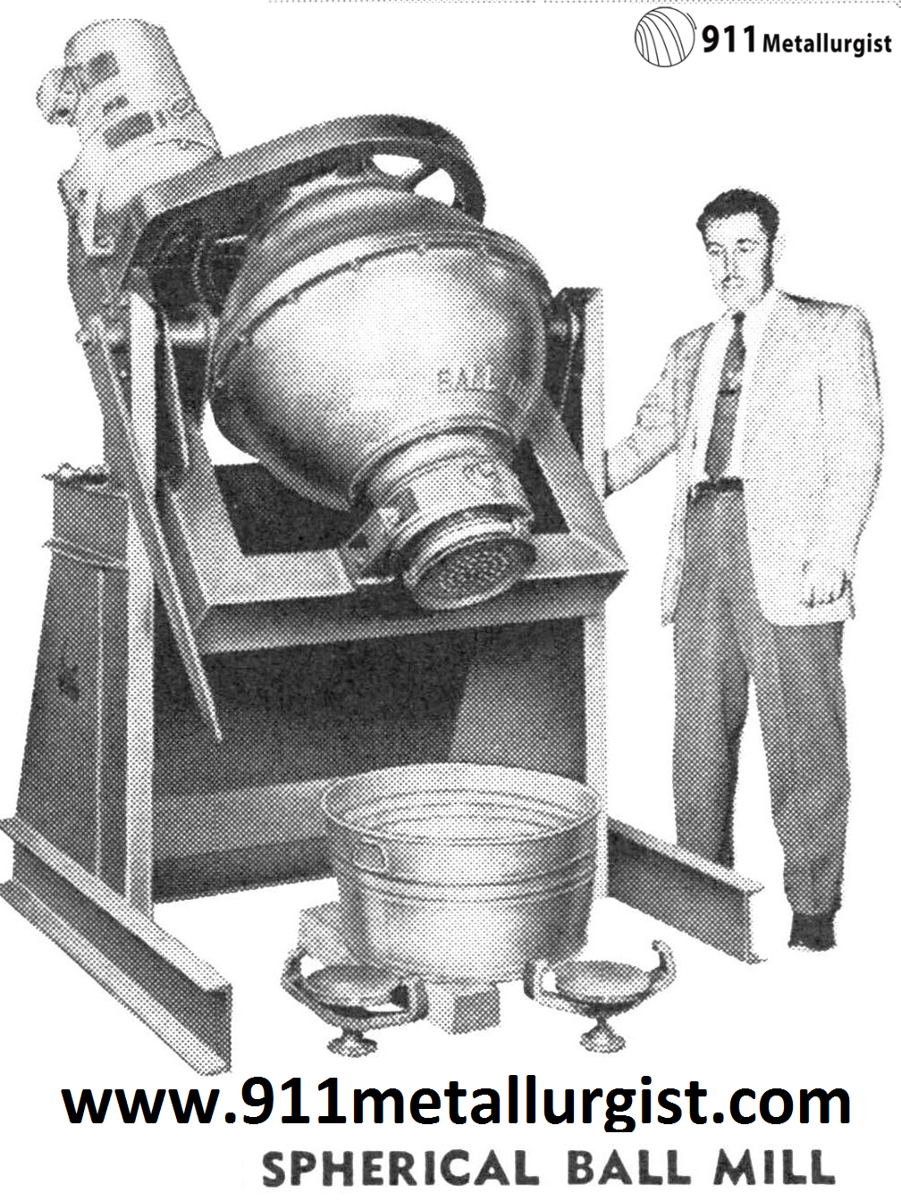
SPHERICAL BALL MILL
A special purpose batch mill designed especially for grinding and mixing involving acids and corrosive materials. No corners mean easy cleaning and choice of rubber or ceramic linings make it corrosion resistant. Shape of mill and ball segregation gives preferential grinding action for grinding and mixing of pigments and catalysts. Made in 2′, 3′ and 4′ diameter grinding drums.
 Contact me if you need a small ball mill.
Nowadays grinding mills are almost extensively used for comminution of materials ranging from 5 mm to 40 mm (3/16″—1 5/8″) down to varying product sizes. They have vast applications within different branches of industry such as for example the ore dressing, cement, lime, porcelain and chemical industries and can be designed for continuous as well as batch grinding.
Ball Mills
Ball mills can be used for coarse grinding as described for the rod mill. They will, however, in that application produce more fines and tramp oversize and will in any case necessitate installation of effective classification. If finer grinding is wanted two or three stage grinding is advisable as for instant primary rod mill with 75—100 mm (3″—4″) rods, secondary ball mill with 25—40 mm(1″—1½”) balls and possibly tertiary ball mill with 20 mm (¾”) balls or cylpebs. To obtain a close size distribution in the fine range the specific surface of the grinding media should be as high as possible. Thus as small balls as possible should be used in each stage.
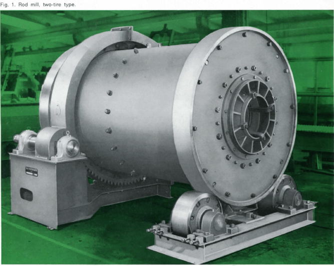
Rod Mills
The principal field of rod mill usage is the preparation of products in the 5 mm—0.4 mm (4 mesh to 35 mesh) range. It may sometimes be recommended also for finer grinding. Within these limits a rod mill is usually superior to and more efficient than a ball mill. The basic principle for rod grinding is reduction by line contact between rods extending the full length of the mill, resulting in selective grinding carried out on the largest particle sizes. This results in a minimum production of extreme fines or slimes and more effective grinding work as compared with a ball mill. One stage rod mill grinding is therefore suitable for preparation of feed to gravimetric ore dressing methods, certain flotation processes with slime problems and magnetic cobbing. Rod mills are frequently used as primary mills to produce suitable feed to the second grinding stage. Rod mills have usually a length/diameter ratio of at least 1.4.
Tube Mills
Tube mills are in principle to be considered as ball mills, the basic difference being that the length/diameter ratio is greater (3—5). They are commonly used for surface cleaning or scrubbing action and fine grinding in open circuit.
Pebble Mills
In some cases it is suitable to use screened fractions of the material as grinding media. Such mills are usually called pebble mills, but the working principle is the same as for ball mills. As the power input is approximately directly proportional to the volume weight of the grinding media, the power input for pebble mills is correspondingly smaller than for a ball mill.
 |
Wet or dry grindingA dry process requires usually dry grinding. If the feed is wet and sticky, it is often necessary to lower the moisture content below 1 %. Grinding in front of wet processes can be done wet or dry. In dry grinding the energy consumption is higher, but the wear of linings and charge is less than for wet grinding, especially when treating highly abrasive and corrosive material. When comparing the economy of wet and dry grinding, the different costs for the entire process must be considered. |
Method of Mill Discharge
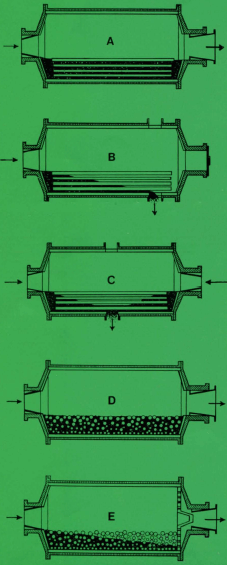 |
Overflow Rod Mill: Recommended for normal wet grinding in rod mills. The diameter of the discharge trunnion is larger than that of the feed trunnion giving an easy material flow through the mill. The discharge trunnion can be furnished with a trommel screen to remove rod fragments, wooden chips etc. from the mill discharge. |
| Rod Mill with End Peripheral Discharge: Used when a moderately coarse product is desired. | |
| Rod Mill with Centre Peripheral Discharge: Suitable for dry grinding at extremely high capacities and very coarse grinding, wet or dry. Also applicable for very viscous material and humidities of 3—15 % by weight. | |
| Overflow Ball Mill: Suitable for almost all applications where a ball mill is required. Simple and trouble-free grinding method. The discharge trunnion can be furnished with trommel screen. | |
| Grate Discharge Ball Mill: This type of mill usually works with a high circulating load and thus produces very little extreme fines. The specific power consumption is therefore less than for an Overflow Mill. A Grate Discharge Mill will also have 15—25 % higher capacity per volume unit as compared with an Overflow Mill. The discharge trunnion can be furnished with trommel screen. |
Optimum Ball Mill Speed
Mill speed is generally referred to as a percentage of critical, which is defined as the speed at which an infinitely small particle just follows a smooth shell lining in its motion.
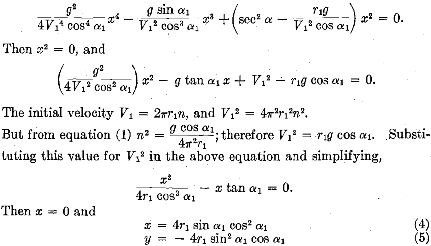
An increase in the mill speed will give a directly proportional increase in mill power but there seems to be a square proportional increase in the wear. Rod mills generally operate within the range of 60—75 % of critical speed in order to avoid excessive wear and tangled rods. Ball and pebble mills are usually operated at 70—85 % of critical speed. For dry grinding the speed is usually somewhat lower.
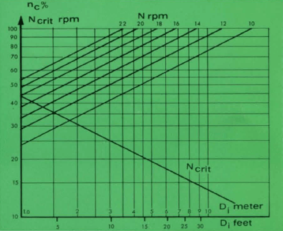
Example : A mill with 4.5 m dia (15′) N obtained = 20 rpm.
If N = 15 rpm nc obtained = 75 %.
Ball Mill Lining
The mill lining can be made of rubber or different types of steel (manganese or Ni-hard) with liner types according to the customers requirements. For special applications we can also supply porcelain, basalt and other linings.
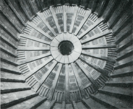
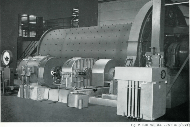
Fig. 3. Rubber lining, grate mill.
Ball Mill Charge volume
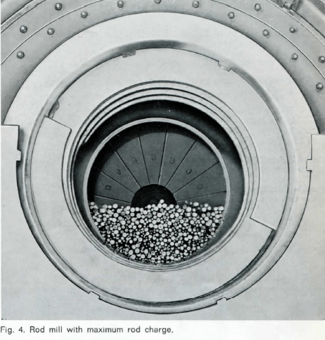
The mill power is approximately directly proportional to the charge volume within the normal range. When calculating a mill 40 % charge volume is generally used. In pebble and ball mills quite often charge volumes close to 50 % are used. In a pebble mill the pebble consumption ranges from 3—15 % and the charge has to be controlled automatically to maintain uniform power consumption.
The volumetric density of a rod and a ball charge is around 4.9 ton/m³ (310 lb/cu.ft) corresponding to 37 % void space.
Sizing of Mills
Factors influencing the mill size are:
- Type, hardness and screen analysis of feed
- Desired product size after grinding
- Required capacity
In all cases the net energy consumption per ton (kWh/ton) must be known either from previous
experience or laboratory tests before mill size can be determined. The required mill net power P kW ( = ton/hX kWh/ton) is obtained from
- P = const. x c x q x nc x Li x Di2.5
- where an approximate figure for the constant is 3.5 for rod mills, 4.0 for overflow ball or pebble mills and 4.5 for grate discharge ball or pebble mills.
- ç is specific gravity of grinding media (for rods or balls normally 7.85)
- q is the charge volume in fraction of mill volume (40 % = 0.40)
- nc is the mill speed in fraction of critical speed
- Li and Di are length and diameter inside shell lining respectively (in meters)
For a mill with more than 2.1 m (7′) diameter the total power is obtained by dividing net power by 0.85.
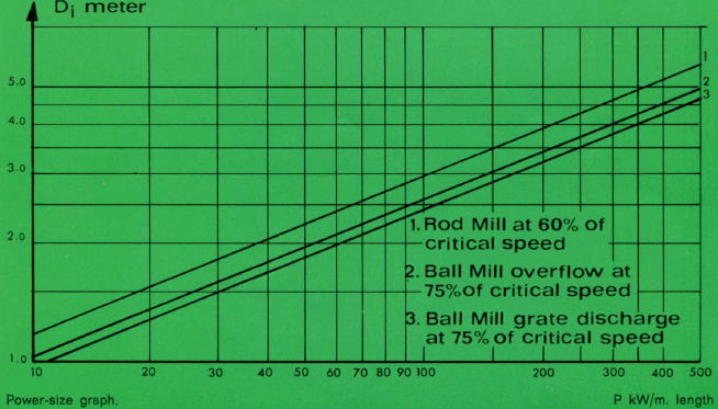
The graph is based on 40% charge volume.
Ball Mill Manufacturing
Shell of steel plate quality B.S. En. 2 B arch welded, stress relieved and with machined flanges. If desired the shell can be provided with manholes.
Heads of S.G. iron (nodular) or steel castings with machined and drilled connection flanges to shell and trunnion.
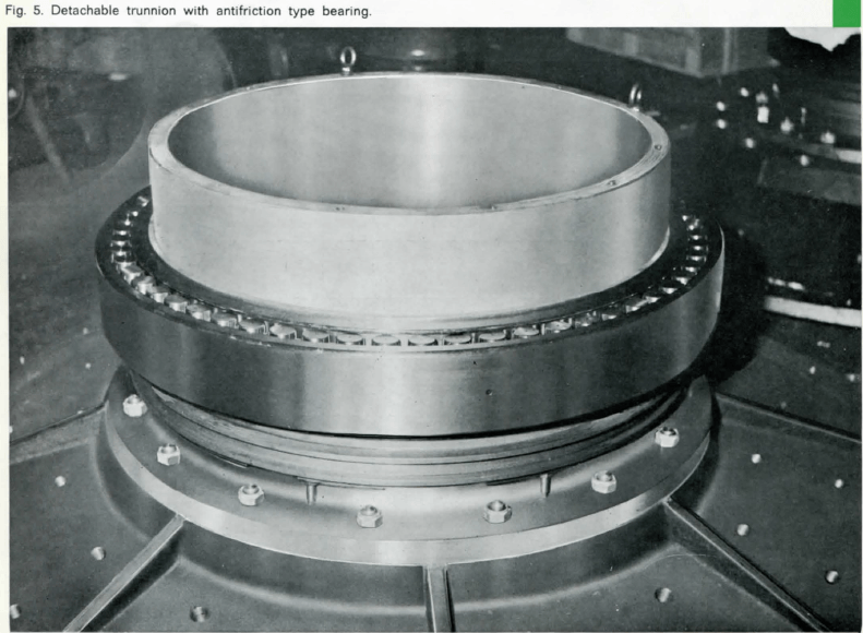
Trunnions of S.G. iron or steel castings with machined flange and bearing seat incl. device for dismantling the bearings. For smaller mills the heads and trunnions are sometimes made in grey cast iron.
Bearings and housings of SKF anti-friction type or self-aligning ball and socket type.
Gearing of spur type in S.G. iron or steel with cut teeth.
Pinion of steel quality B.S. En 43 with cut teeth and flame hardened to suitable hardness.
Pinion Shaft of quality B.S. En 43, press fitted and key locked to the pinion and carried in two SKF standard anti-friction bearings. For bigger mills the pinion shaft is integral with the pinion.
Speed Reducer with cast iron casing and shafts and gears of special steel carried in anti-friction bearings.
Flexible Couplings provided between motor and speed reducer as well as between speed reducer and pinion shaft.
Ball Mills for laboratories and pilot plants
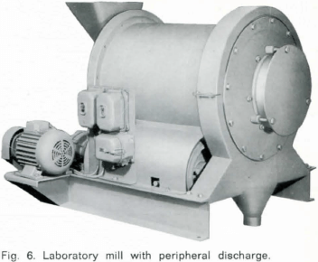
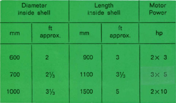
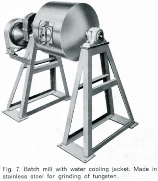
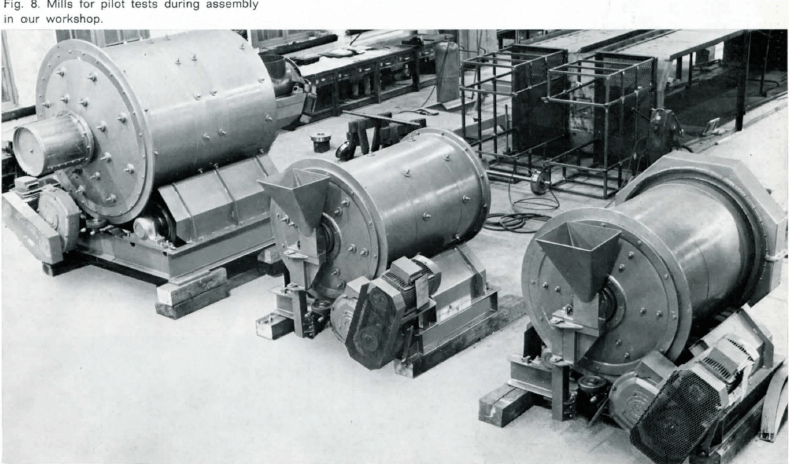
| For smaller capacities and laboratory use we manufacture grinding mills with sizes according to the table below. These ball mills are built on a steel frame, on which the complete drive is also installed. The mill runs on rubberized rollers, which are driven via torque arm speed reducers and rope drives from two standard squirrel-cage motors. The speed reducers are of standard type running in oil in dust-tight housings.
The mills can be used either for dry or wet, rod or ball grinding. By using a separate attachment the discharge end can be changed so that the mills can be used for peripheral instead of overflow discharge. The lining is generally made as a plate of wear resistant steel with welded on lifters. The heads are bolted onto the shell which simplifies the change of lining. |
 |
 |
 |
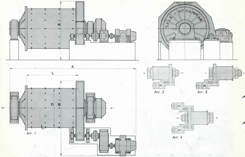
Ball Mill Shell Dimensions VS Motor Sizes
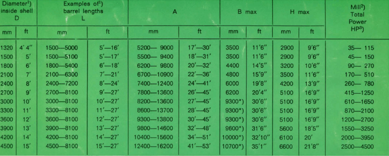
- Diameters and barrel lengths are manufactured with a modulus of 300 mm (abt. 1′). Tube mills with greater lengths than shown in the table can be delivered. For calculations of power input and critical speed the diameter and length should be reduced with the liner thickness.
- Ball mill grate discharge with 40 % charge and speed 75 % of critical. For rod mills with 40 % charge and 60 % of critical multiply power figure by 0.60.
- Drive motor with min. 10 % higher power should be chosen.
Dual drive as per arr. 4. All measurements are for preliminary use only.
How to Size a Ball Mill -Design Calculator & Formula
 A) Total Apparent Volumetric Charge Filling – including balls and excess slurry on top of the ball charge, plus the interstitial voids in between the balls – expressed as a percentage of the net internal mill volume (inside liners).
B) Overflow Discharge Mills operating at low ball fillings – slurry may accumulate on top of the ball charge; causing, the Total Charge Filling Level to be higher than the Ball Filling Level. Grate Discharge mills will not face this issue.
C) This value represents the Volumetric Fractional Filling of the Voids in between the balls by the retained slurry in the mill charge. As defined, this value should never exceed 100%, but in some cases – particularly in Grate Discharge Mills – it could be lower than 100%. Note that this interstitial slurry does not include the overfilling slurry derived from the difference between the Charge and Ball Filling.
D) Represents the so-called Dynamic Angle of Repose (or Lift Angle) adopted during steady operation by the top surface of the mill charge (“the kidney”) with respect to the horizontal. A reasonable default value for this angle is 32°, but may be easily “tuned” to specific applications against any available actual power data.
Mill Selection
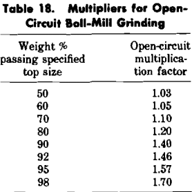
The first step in mill design is to determine the power needed to produce the desired grind in the chosen ore. The most used equation, for this purpose, is the empirical Bond equation (Bond, 1960, 1961; Rowland and Kjos, 1978).

In this equation, E is the specific energy required for the grind, and F80 and P80 are the sizes in micrometers that 80% of the weight passes of the mill feed and product respectively. The parameter Wi, known as the work index of the ore, is obtained from batch bench tests first devised by Bond (1961). The power calculated on using equation 1, (Bond, 1961; Rowland and Kjos, 1978), relates to:
1) Rod milling – a rod mill with a diameter of 2.44 meters, inside new liners, grinding wet in open circuit.
2) Ball milling – a ball mill with a diameter of 2.44 meters, inside new liners, grinding wet in open circuit.
When the grinding conditions differ from these specified conditions, efficiency factors (Rowland and Kjos, 1978) have to be used in conjunction with equation 1. In general, therefore, the required mill power is calculated using the following equation

where n is the number of efficiency factors, EFi, used and fo is the feed rate of new ore to the mill. The power calculated from equation 2 can be looked up in published tables (Rowland and Kjos, 1978) and the correct mill size and type can be selected.
Note that any efficiency factors can be dropped from equation 2 on substituting the work index, Wi, in equation 1 by an effective work index, Wie where

The philosophy in the development of the MRRC grinding simulation package was to build interactive software that could be used as an inexpensive means of providing a semi-quantitative check on a grinding mill design. In addition the software is designed to “slot in” to a general mineral processing package now undergoing development at the MRRC.
The software, written in BASIC+, and implemented on a Dec 11/60 computer, consists of three main programs:
- input program: – gr dat
- well-mixed flow simulation:- – gr mix
- plug flow simulation: – gr plug
Ball Mills
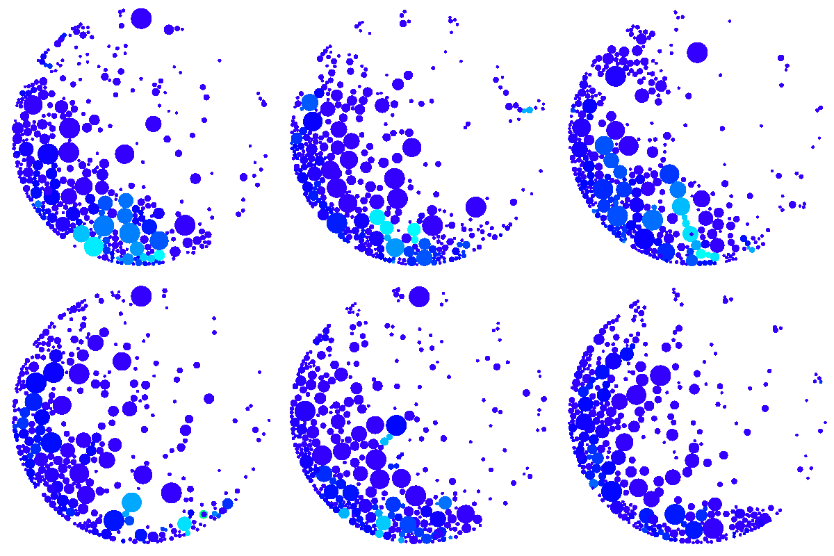
The ore from the crushing section is delivered to the fine ore bin placed at the head of the grinding section, from which it is fed, together with water, to one or more grinding units consisting of a ball mill or rod mill in circuit with a classifier. One such unit with a conical ball mill is shown in Fig. 9. A ball mill consists essentially of a conical or cylindrical shell supported on hollow trunnion bearings on which it revolves; the construction of the various types is described later. The ore enters through one trunnion and leaves by the other. The mill is kept about half-full of balls and is driven at the speed at which their cascading and rolling action has the maximum crushing and grinding effect on the ore as it passes through under pressure of incoming feed ; the cascading action crushes the ore by impact and the rolling action grinds it by attrition. In a rod mill steel rods replace the balls; the cascading action is less, and the rolling action is responsible for most of the work done.
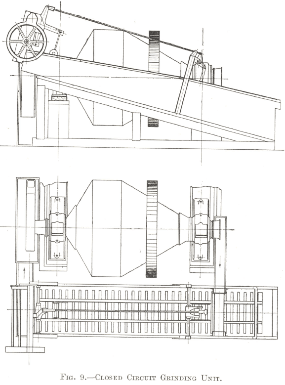
The pulp is discharged into a classifier where it is further diluted with water. The classifier is adjusted so that the ore which has been crushed fine enough overflows with the water at its lower end, while all coarser particles are transported back to the feed end of the mill. Thus a circulating load is maintained round the circuit and any particles of ore that are too coarse to overflow pass through the mill again ; they continue to go round the circuit in this way until they have been crushed fine enough to be discharged. This circulating load may amount to five or six times the weight of new feed entering the circuit. However carefully the classifier is regulated, many particles are crushed so small that when they finally escape they are very much finer than is required. In practice it is always found that the discharge contains all sizes of particles from the maximum allowable size, as determined by the setting of the classifier, down to the finest slime. For example, if a classifier were set to give a discharge of 5% plus 48 mesh material, the proportion finer than 200 mesh would probably amount to 45% ; this would be termed “ 48 mesh grinding ”. The amount of minus 200 mesh material produced at a given “ mesh of grinding ” varies according to the physical condition of the ore, but it is usually between the following limits:
Fine grinding to 100 mesh or more is best done in two stages, and the present tendency is to extend this practice to grinding as coarse as 48 mesh. The original method was to pass the ore straight through the primary mill without classification (open circuit) to a secondary circuit similar to the arrangement of Fig. 9 (closed circuit). Greater efficiency in grinding is now obtained by adding a classifier to the first stage so as to convert it into a closed circuit. The overflow of the primary classifier passes to the second stage and the overflow of the secondary classifier is the finished product of the grinding section.
Ball Mill Grinding P80 Size
The mesh of grinding usually lies between 48 and 200 mesh. On account of their size in relation to that of the bubbles, particles larger than 48 mesh generally have too great a tendency to drop out of the froth and escape in the tailing, while the lower limit is determined by the fact that grinding finer than 200 mesh is usually too costly to be economical, rather than by any factors affecting flotation.
In theory the critical mesh of grinding should depend on the size of the smallest particle of mineral as it occurs in the ore. In order that the valuable minerals may be separated from the gangue in the flotation machines, they must have been more or less completely released from the rock-forming and other minerals with which they are associated, and for an ideal separation they would have to be entirely free, but in practice this is often undesirable and uneconomical on account of the fact that the operation of grinding is more costly than that of any other section of the flotation plant, for which reason the ore should not be crushed any finer than is necessary.
It has already been pointed out that a ball mill inevitably produces a considerable quantity of material that is too fine. In addition, the mineral is generally more friable than the rest of the ore, and is therefore ground proportionately finer than the gangue ; consequently the largest particles in the classifier overflow consist mainly of gangue with only a small proportion of mineral. For these reasons the mesh of grinding can generally be much coarser than the size of the smallest particle of mineral in the ore. If, however, the product is so coarse that the mineral is locked up in the gangue, it passes out with it in the tailing and the recovery suffers, but it must be remembered that it is often possible to float mineral which has not been completely liberated from the gangue and has only a portion of its surface exposed ; in this case the recovery of the mineral does not suffer, but the grade of the concentrate is reduced in proportion to the amount of gangue that enters it attached to the particles of mineral.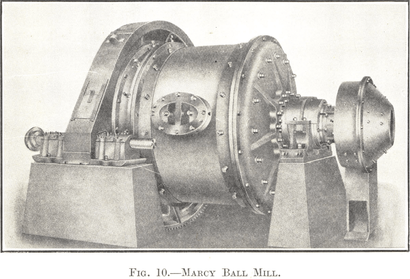
The correct mesh of grinding for any particular ore can be determined within certain limits by small-scale tests, but it can only be finally settled by experiment in the plant itself. It is always a compromise between the completeness of the liberation of the valuable minerals and the cost of grinding, and it depends to a certain extent on the physical characteristics of the ore as they affect grinding and of the minerals as they affect flotation.
Cylindrical Ball Mills
The only cylindrical ball mills in common use are those of the grate discharge type, the most important being the Marcy and the Allis-Chalmers mills.
Fig. 10 illustrates the construction of the Marcy Ball Mill. The cylindrical shell and the feed and discharge heads are made of cast semi-steel. The hollow trunnions at each end run in self-aligning bearings and are fitted on the inside with manganese steel liners to protect them from wear. The feed-end liner is made with a deep spiral screw on the inside to facilitate the entrance of the feed, but the liner at the discharge-end is smooth. A scoop feeder is bolted to the trunnion at the feed end. As most of the wear occurs at the end of the scoop when it digs into the material in the feed-box at every revolution, this point is provided with a renewable lip of manganese steel.
The shell liners are of the rectangular overlapping type and are made of manganese steel. They vary from 3 to 5 in. in thickness at the deepest part of the section according to the size of mill for which they are intended. The feed-end liners are also made of manganese steel and vary in thickness at the deepest part from 2 to 4½ in.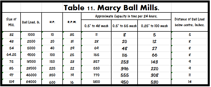
The discharge head and trunnion are shut off from the interior of the mill by a grate assembly which is shown in Fig. 11. It consists of a number of grate sections held in place by clamp bars which fit over the junctions between the sections and are bolted to the head. Radial spacing and lifting ribs, cast in one piece with the head and arranged parallel to the clamp bars, keep the whole assembly several inches clear of the end of the mill. The space so formed is thus divided by the ribs into the same number of compartments as there are grates, each compartment being open at its apex to the discharge-end trunnion.
All the material that passes through a grate when it is in its lowest position collects in the compartment behind and is carried up by the revolution of the mill until it can flow out by gravity through the opening at the apex. This is shaped so as to deflect the pulp into the trunnion, through which it is discharged from the mill.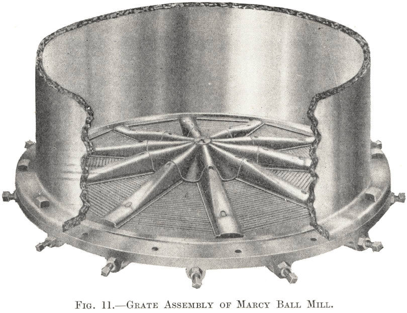
The bars composing the grates are made of high-carbon tempered tool steel with a certain proportion of chromium and are welded up into sections. They are tapered slightly towards the discharge side to prevent choking, and the spacing between them varies from 3/16 to 3/8 in. according to the work required of the mill. The direction of the slots is designed to present an almost continuous opening to the pulp as the mill revolves, and the arrangement provides an efficient and rapid method of discharge into the lifting compartments behind. The radial clamp bars assist the passage of the pulp through the grates to some extent by keeping them clear of balls and large pieces of ore, protecting them at the same time from excessive wear.
The mill is filled with balls to a level several inches below the axis. The ball load, speed, etc., are regulated so that under normal running conditions most of the ore is small enough to pass through the grates by the time that it reaches the discharge end. At the feed end the pulp enters at the level of the trunnion, but its level gradually falls along the length of the mill until at the discharge end it passes freely through the grates at a point only a few inches above the periphery of the shell. Thus the intensity of grinding is greatest at the feed end where it is needed, but diminishes towards the discharge end owing to the gradually increasing rate of travel of the particles of ore, a condition which tends to reduce overgrinding. With a similar object in view this type of mill is designed with its diameter greater than its length so as to achieve the maximum grinding effect in the minimum time.
The capacities, power requirements, etc., of the various sizes of Marcy Ball Mills are given in Table 11. It should be noted that the first figure of the number of a mill represents its diameter, and the second one its length.
The Allis-Chalmers Ball Granulator is made on the same principles as the Marcy Ball Mill, but differs considerably in detail. One of the main points of difference is in the design of the grate assembly. A diaphragm, perforated with round holes, shuts the discharge compartments off from the interior of the mill. The grates are mounted on the front of the diaphragm, the openings between the bars being arranged radially instead of circumferentially as in the Marcy Mill. Any material that gets through the grates has also to pass through the holes of the diaphragm, the purpose of which is to enable the pulp level to be raised if necessary. This adjustment is effected by plugging up one or more of the outermost rows of holes, and the level can in this way be brought up to a point halfway between the periphery and the axis of the mill. For grinding to 65 mesh or coarser the lowest possible discharge is generally found to give the best results, the ability to raise the pulp level being a doubtful advantage ; the adjustment is useful, however, for finer grinding. While it is possible in both types of machine to bring up the level by increasing the amount of water added to the pulp, this does not always give satisfactory results. The Allis-Chalmers design has the advantage that the level can be altered without interfering with the W/S ratio of the pulp. Its grate area, however, is not as large as that of a Marcy Mill of the same diameter and the radial arrangement of the bars does not give such a free discharge as is obtained when they are in a circumferential direction. Thus the Marcy Mill has the advantage in cases where the lowest possible discharge level is required.
Conical Ball Mills
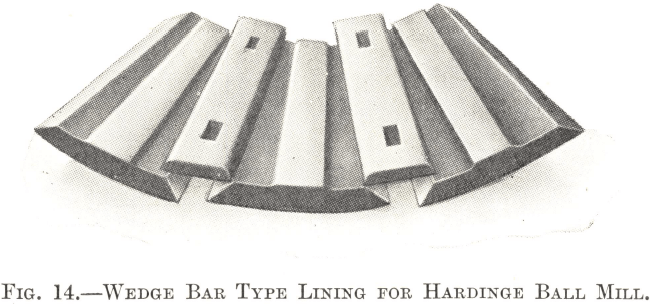
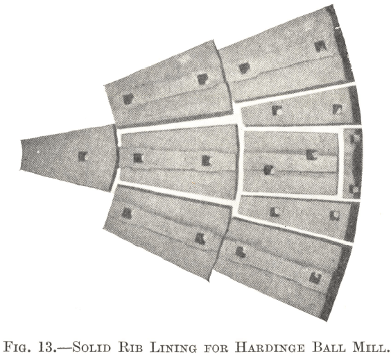
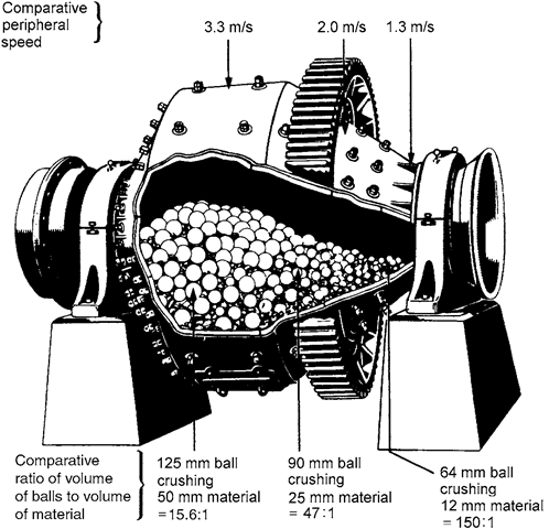 The only conical ball mills on the market are those made by the Metso. Fig. 12 shows the construction of this type of mill. It consists essentially of a short cylindrical section with conical feed and discharge ends. The shell is made up of steel plates riveted or welded together. The hollow feed and discharge trunnions are riveted or welded to the conical ends and run in bearings of ample size ; they are protected from wear on the inside by cast-iron liners. The feed trunnion carries a scoop feeder of the type shown in Fig. 16. The shell is lined with specially shaped sections of chrome or manganese steel, each of which is held in position by two bolts ; these are illustrated in Fig. 13. A cheaper lining, shown in Fig. 14, consists of cast-iron plates clamped in place by wedge bars, the bars being secured to the shell by two bolts each. The bars are of chrome steel and project above the plates ; the thickness of each is such that they are both worn out at about the same time.
The cone at the feed end of the mill is steep in order that the incoming material may pass as rapidly as possible into the cylindrical section which constitutes the zone where the grinding action is most intense. The length of the cylindrical part is only about half its diameter, the proportions being designed to keep overgrinding at a minimum while still reducing as much of the ore as possible to a size suitable for the “ finishing ” stage in the conical section at the discharge end. The slope of the cone at this end is not as steep as at the feed end and a decided classification of the material takes place inside it. It is most noticeable in the case of the balls, the smallest sizes of which segregate at the smallest diameter of the cone and vice versa. 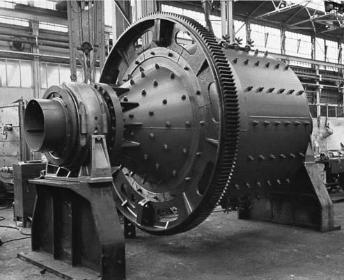 The segregation of the ore is similar but is not so marked ; this is chiefly due to the irregularity in the shape of the pieces and to the continual surging motion inside the mill, which interferes with the proper classification of the comparatively light particles of ore in the cone while scarcely affecting the much heavier balls. The general tendency is for the largest pieces of ore to remain with the largest balls at the bottom of the cone where the intensity of grinding is greatest, and for the finest particles to segregate at the smallest diameter with the smallest balls where the intensity of grinding is least.
Overgrinding is therefore reduced to a minimum and the smallest particles rise in preference to the larger sizes to the apex of the cone where they are discharged. In order to get the most economical consumption of power, the ball load in a Hardinge Mill should be kept up to the level of the trunnions.
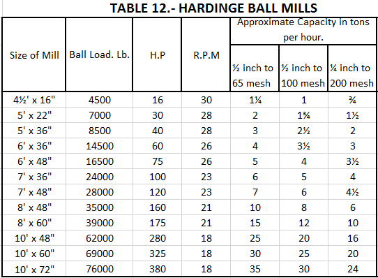
The capacities, power requirements, etc., of the various sizes of Hardinge Ball Mills are given in Table 12. It should be noted that the two figures describing the size of a mill represent the diameter of the cylindrical section in feet by its length in inches.
Rod Mills
A rod mill is a long cylindrical mill without grates using rods as a grinding medium. Its length is usually twice its diameter, the most popular size being 6 ft. in diameter by 12 ft. in length; the largest made up to the present is 9 ft by 12 ft.
The first two are fitted with trunnions at both ends, the opening at the discharge end being rather larger than at the feed end. The Marcy Mill, however, has a trunnion at the feed end only ; round the shell at the other end is bolted a tyre which runs on two supporting rollers. This construction makes it possible to provide a very large opening in the discharge head, which enables a correspondingly low pulp discharge level to be maintained and so helps to reduce overgrinding in much the same way as in a ball mill with discharge grates ; it also gives very convenient access to the interior. The discharge opening is provided with a splash door which swings on an independently supported hinge ; in the closed position it is held a few inches clear of the discharge head, leaving an annular opening through which the pulp can pass without undue splash. The Hardinge Mill has conical ends.
The mills are charged with high-carbon steel rods cut a few inches shorter than the interior length of the mill. As a rule 3-in. diameter rods are employed for primary and 2-in. for secondary grinding. The shell liners are usually of chrome steel of the ordinary rectangular pattern.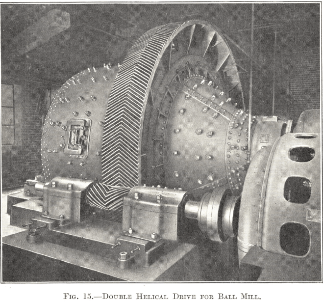
A load of rods has more of a rolling and less of a cascading motion than a load of balls, and the shattering effect of the rods on the ore is consequently not as great as that of balls. While it is possible, if not advisable, to allow pieces of 2″ or even 3″ size in a ball mill, it is essential that the feed of a rod mill should be no larger than 1-in. and preferably smaller. For the same reason the ore must be friable ; rods cannot compete with balls in grinding hard or tough material.
Since the surface area of a load of rods is much less than that of a load of balls occupying the same space, the ore is not ground so fine in a rod mill as it would be in a ball mill of the same size. Moreover, a given feed of ore passes more quickly through a rod mill, since the percentage of voids in a rod load is less than in a ball load. A rod mill generally works best with a thick pulp, which should be viscous enough to stick to and coat the rods to some extent. The larger pieces of ore keep the rods apart so that the grinding action is concentrated on the larger sizes and the smaller particles are not overground to the same extent as in a ball mill.
For these reasons the shell is made about 50% longer than that of a ball mill of the same diameter and still gives less undersize when grinding the same tonnage to the same mesh. In fact, the characteristic of the rod mill is the unusually granular nature of its product but, because the larger pieces keep the rods apart, a rod mill will not grind efficiently below 65 mesh and it works best at a comparatively small reduction ratio. Its most efficient range is usually from about ½ in. to 20 mesh, and, when grinding finer, it is com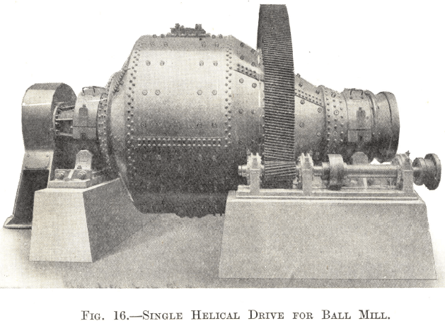 mon practice to employ two stages, each in closed circuit with a classifier.
Although rod mill installations are thus restricted in normal practice to the coarse crushing of soft and friable ores, it is sometimes found that the most economical method of grinding an ore of not more than average hardness is to use a rod mill in the primary and a ball mill in the secondary stage. Such a circuit is not uncommon in large plants, but it is seldom adopted in small installations, for which it is generally found preferable to provide each stage with the same type of mill in order to facilitate maintenance and repairs.
On the class of work for which it is especially suitable the power consumption of a rod mill is about three-quarters that of a ball mill with the production of less undersize. The rod and liner consumption is also about 75% of that of a ball mill, and rods cost less than balls because they are more easily manufactured. Outside of this special sphere of work a rod mill cannot compete with a ball mill.
Ball Mill and Rod Mills Drives
In all cases, except in a few laboratory sizes, ball and rod mills are driven by a pinion which is mounted on a counter-shaft and engages with a gear-wheel bolted to the shell. For small machines the simplest way of driving the countershaft is by belt and pulley to a motor, Tex-ropes being preferable to a flat belt because the distance between pulley centres can be much shorter, making a more compact layout, and there is less danger of accident in the event of breakage. Ordinary spur gearing is used for the gear-wheel and pinion.
A belt drive is unsuitable for large mills and present practice is to connect the counter-shaft directly to a slow-speed motor through a flexible coupling, using double helical gearing for the gear-wheel and pinion. This method is illustrated in Fig. 15. Fig. 16 shows a single helical drive with thrust bearing, which is a recent development of the direct drive and is somewhat simpler and easier to maintain in adjustment than the double helical gear. The slow-speed motor and helical gearing, however, make the direct drive rather expensive ; a cheaper way is to use ordinary spur gearing and to drive the counter-shaft by a high-speed motor through a train of gears and a flexible coupling. This method is preferable to a belt-drive, but a direct drive gives less trouble on the whole than any other.
Grinding Media & Ball Mill Liners
Balls are made of cast-iron, high-carbon, and chrome steel. Cast-iron balls are only used as a rule when they can be cheaply produced locally with no charge for freight. Ordinarily high- carbon or chrome forged steel balls give a lower cost per ton of ore ground on account of their better wearing qualities, although they are more expensive in first cost.

Table 13 is a rough guide to the wear that may be expected from the three classes of balls. Their average relative grinding ball consumption is approximately as follows:
Chrome: high-carbon: cast-iron = 100 : 140 : 170.
Their average factory cost is:
Chrome: high-carbon: cast-iron = 100 : 95 : 75.
 If, therefore, the freight charge is not taken into consideration, chrome steel balls show a lower cost per ton of ore ground than those of high-carbon steel, and the latter show a lower cost than those of cast- iron. The freight charge per pound of metal is the same for all classes of balls, but the freight cost per ton of ore ground is less for chrome steel than for high-carbon steel because it is spread over a larger tonnage of ore ; similarly, the cost per ton of ore for high-carbon steel is less than for cast-iron. It follows that, when freight charges are high, it is cheapest to use the steel that wears longest, even though it is the most expensive in first cost, but if balls can be made or bought locally at a reasonably cheap rate, the cost of freight is eliminated, and it may pay to use them in preference to a more expensive class of ball that has to be imported. This is the reason in most cases for the employment of cast-iron balls, which will generally be found to come from a local foundry. They are not satisfactory, however, when their diameter exceeds 2½ in., since they break up too quickly and give rise to an excessive consumption of iron.
The above considerations apply also to the linings of ball and rod mills. Liners of cast-iron can be substituted for chrome or manganese steel, but, as a general rule, they only show a lower cost per ton of ore ground when they can be produced locally and when steel liners would have to bear a heavy freight charge.
For rough calculations the wear of liners is usually reckoned to be 25% of the ball consumption when both are made of the same material.
The size of the balls used for grinding depends on the size of the material entering the mill; they should be just large enough to break the biggest lump of ore likely to be encountered. Balls of 5-in. diameter are the largest in common use, but they are only suitable for coarse feeds of 1-in. size or over. Balls from 3 to 4 in. in diameter are ordinarily employed in mills when the feed consists of the discharge of a cone crusher, while 2 to 2½-in. balls are necessary for secondary grinding. They are not made in diameters smaller than 2 in. The first charge of balls is graded to give the minimum percentage of voids, but the largest size only is added subsequently to make up for wear, as the balls themselves wear down more or less automatically in such a way as to give the minimum volume of voids.
Cylindrical VS Conical Ball Mills
For coarse grinding the cylindrical grate mill will, as a rule, give a lower consumption of power per ton of ore than a conical mill. The reason for its better performance lies in the low pulp discharge level which reduces overgrinding at the point where it would do most harm—i.e., at the discharge end of the mill. Thus the least possible amount of power is wasted in grinding material that is already too fine and more power is therefore available to do useful work in grinding ore that is not fine enough.
For fine grinding, on the other hand, it is usually found that the conical mill is the more economical. A fine product demands the use of smaller balls than a coarse one, since the smaller particles of ore can be broken with a lighter blow, and, as has already been explained, in this type of mill the balls tend to grade themselves automatically in the conical discharge end according to size, the smallest balls lying in the smallest diameter. The mill feed, therefore, is reduced in the cylindrical section to a size suitable for the final stage, overgrinding being kept to a minimum by making the length of this section short compared with its diameter, and it then enters the finishing zone in the conical discharge end. Here, as the size of the balls progressively decreases, there is a corresponding increase in the area of grinding surface per unit of ball charge volume and so in the efficiency of grinding, and the particles, passing through the cone from smaller to smaller balls, receive successively lighter and lighter blows, with the result that a more uniformly ground product is made than is possible in a cylindrical grate mill, in which the composition of the ball charge at the discharge end is the same as at any other point.
The above explanation is largely conjecture, but it can be stated as a fact that an analysis of flotation mill construction during the last few years shows that the Marcy type of ball mill is preferred for coarse and the Hardinge type for fine grinding.
For medium grinding between 65 and 100 mesh some difference of opinion exists as to which type of mill is the better. Other conditions being equal, the Hardinge Mill possesses the advantage that it can be relined without lifting the shell off the trunnion bearings, whereas a grate mill has to be taken off its bearings and dismantled for some of the routine replacements.
This advantage may be worth considering in a small plant, but it is negligible in a large installation where maintenance work can be better organized. The decision to install a particular make of mill for medium grinding has often depended on the fact that the type has previously proved satisfactory in an existing plant or in the locality. For a small company that cannot afford to experiment there is a good deal to be said for such a policy.

