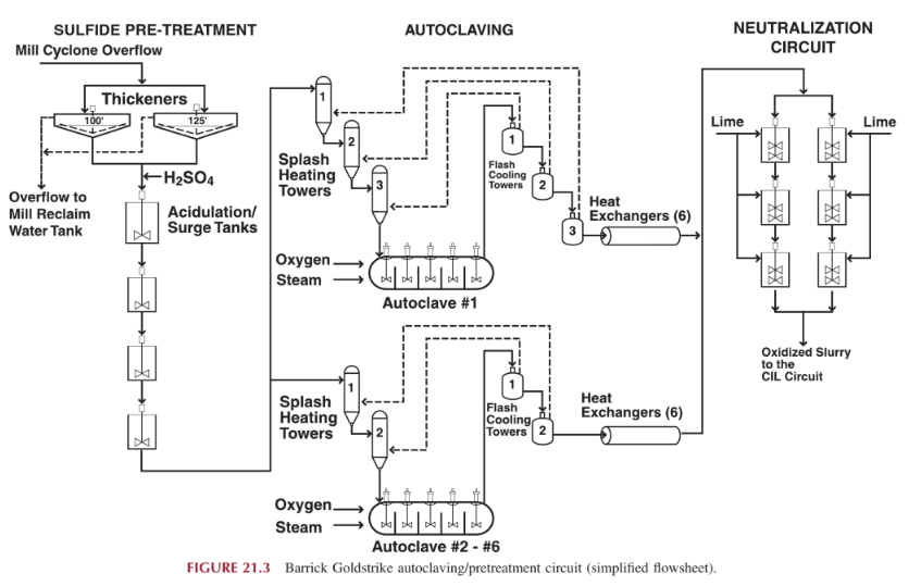
Slurry from the grinding circuit, at approximately 35% solids and 80—85% passing 135 mm is pumped to three thickeners. Thickener underflow, at approximately 54% w/w solids, is pumped to a train of four acidulation tanks. Sulfuric acid is added to the slurry to destroy sufficient carbonate prior to entering the autoclave circuit. Process air is also injected into the acidulation tanks to aid in carbon dioxide removal. Carbonate levels are typically reduced to <2% in the acidulation tanks.
As a rule of thumb, about 1% sulfide sulfur (S ) in the autoclave feed destroys 0.9% CO3 and typically the autoclave feed ranges from 2.0% to 2.5% S2-. At higher levels of S2-, slightly less than 0.9% CO3 is destroyed for each 1% S2-.
The slurry is advanced from the acidulation tanks through a series of direct contact heater (“splash”) vessels before feeding into the autoclave. The slurry is preheated to a temperature of 165—175 °C as it passes through the splash vessels. The heat source in the splash vessels is the flashed steam, which is released from the slurry discharging from the autoclave as it passes through the pressure let down (“flash”) vessels. The slurry enters the splash vessels at the top and cascades down the internal baffles, while the flashed steam enters the lower section of the vessel and rises, contacting the slurry for direct heat transfer. The bottom of each vessel serves as a pump box for the interstage feed pumps.
The discharge from the high-pressure splash vessel is pumped by two positive displacement piston-diaphragm (Geho) pumps into the autoclave. The pumps are operated in parallel with individual suction and discharge lines. Each pump can deliver approximately 60% of the required feed rate to the autoclave.
All six autoclaves have an outside diameter of 4.6 m; autoclave No. 1 is 23 m in total length, and autoclaves Nos. 2—6 are 25 m in total length. Each autoclave is divided into five compartments, with each compartment containing an agitator and injection pipes for oxygen, steam and water. Autoclave retention time ranges from 40 to 60 min, and the vessel operates at approximately 2900 kPag and 215—220 °C. The corrosion-resistant membrane of the autoclave vessels is 8-mm-thick chemical lead panel-bonded to the carbon steel shell, thermally protected by 3-mm Fibrefrax™ paper and 23-cm-thick courses of acid-resistant fireclay brick.
Sulfide sulfur oxidation through the autoclave is typically of the order of 90—92%. Residual S exiting the autoclave is targeted at less than 0.2%. Values greater than 0.25% S“ typically result in poorer gold recoveries in the C1L circuit. Free-acid levels in the autoclave discharge are a function of S2 and CO2- in the autoclave feed, but normally range from 10 to 25 g/L H2S04.
The slurry discharges from the autoclave and passes through a series of pressure let down stages called flash vessels. Pressure and temperature are gradually let down to atmospheric pressure and 96 °C, after passing through the flash vessel circuit. The steam released by the instantaneous reduction in pressure through the flash vessel is ducted to the corresponding splash vessel. Slurry leaving the pressure let down circuit is then cooled from 96 to 48 °C by a series of six to eight shell and tube heat exchangers. The cooling water is on the shell side of the heat exchanger and the slurry passes through the tubes. In summary, the flash/splash system is a heat-recovery system, which minimizes the use of direct steam with inherent operating cost benefits. After the slurry passes through the slurry coolers it is pumped to two parallel trains of neutralization tanks, where the pH value is elevated from 1—2 to ~ 10.5.
Neutralized slurry from the pressure-oxidation circuit is pumped to two parallel trains of eight CIL tanks for gold extraction and subsequent recovery of gold in a conventional Zadra elution circuit.
Suitable ancillary facilities are installed to supply flocculant, sulfuric acid, oxygen, lime, steam, and compressed air to the autoclave facility. The control system is a Bailey Network 90™ distributed control system (DCS).
