Table of Contents
In situ recovery of minerals has great potential as a mining technology to mine deposits that might otherwise be overlooked by conventional techniques. Some hard-rock deposits, however, will not have adequate permeability to permit successful in situ mining and will require permeability enhancement of the rock deposit prior to leaching. The leaching process in this instance becomes modified in situ mining rather than true in situ mining.
This paper examines the use of high explosives to create fractures and make ore deposits more permeable which will allow better rates of mineral recovery. Blasting can be used to fragment both orebodies located near the surface and those at depth. If the ore deposit to be leached is well below the surface it may also possess inadequate permeability due to increased in situ stresses, as reported by McKee et al. (1983), and blasting in this case could play an important role in permeability enhancement prior to successful in situ mining.
Although other fracture techniques exist, such as hydraulic fracturing, blasting with high explosives can potentially create a distribution of fractures not achievable by the other techniques. Warpinski et al. (1979) examined multiple fracturing in a volcanic ash-fall tuff formation using three different propellants, and mineback facilities provided the opportunity to directly observe the resulting fracture network. They concluded using high explosives could cause considerable crushing and compaction around the borehole, possibly sealing off any cracks that were formed.
Laboratory studies conducted by Science Applications International Corporation (SAIC) for the Gas Research Institute, and reported by Schatz et al. (1987), involved the numerical prediction and interpretation of multiple radial fractures using black powder and high explosives. Their work, however, was conducted in hydrostone, an easily cast gypsum-based cement, whose physical properties and fracture characteristics are significantly different from deep hard-rock deposits.
Steckley et al. (1975) and D’Andrea et al. (1976, 1977, 1978) conducted blasting experiments to recover copper from deposits by in situ mining, but their research did not involve the application of leach solutions. Ahlness (1983) summarized the Bureau work and concluded that all of the test patterns investigated produced adequate fragmentation for in situ mining.
Very little data exist on the effects of high explosives to enhance the permeability of hard-rock deposits at depth. This paper describes fifteen single-hole laboratory shots which used high explosives detonated in granite blocks to create fractures. Three different polyaxial load cells were used to simulate in situ stresses from 1.72×10 6 to 1.76×10 7 Pa (250 to 2550 psi). All of the blocks were sawed open to expose the fracture network generated by the blasting. The nature and the extent of the fracture patterns are reported.
Confinement Cells
The laboratory test blasts were carried out in polyaxial load frames which simulated in situ stresses and were located in the blasting shelter at Twin Cities Research Center, and in facilities operated by TerraTek Geoscience Services, Salt Lake City, Utah, and SAIC, Las Vegas, Nevada, respectively. The latter two laboratories utilized special equipment to achieve greater stress levels and this equipment was not available at Twin Cities.
The Bureau tests utilized a .51- by .51- by .56-m (20- by 20- by 22-in) confinement cell constructed out of six .019 m (¾ in) thick steel plates. Threaded rods held the cell together. The fully assembled test cell is shown in figure 1. To compensate for blocks of differing size, grout was used to fill the gaps between the block and the assembly walls. After the grout had hardened, the nuts were torqued to give the desired stress level. All of the tests conducted at the Bureau utilized a maximum stress level of 1.72×10 6 Pa (250 psi).
The confinement cells at both TerraTek and SAIC utilized a steel box surrounded by six flat jacks and a hydraulic control system to provide independent pressures on 3 axes of the granite blocks. These cells were capable of simulating three dimensional stresses up to 2.1×10 7 Pa (3000 psi). In the tests conducted for the Bureau the stress levels were varied from 1.72×10 6 to 1.76×10 7 Pa (250 to 2550 psi). All of the confining pressures applied in the tests represented uniform stresses, i.e., there were no variations in differential stress.
Charge Configuration
The general charge configuration consisted of an exploding bridgewire detonator (EBW) taped to the end of a piece of detonating cord, centrally located in the granite blocks, as shown in figure 2. For these tests, 1.6×10-³, 3.2×10-³, or 6.5×10-³ kg (25-, 50-, or 100-grain) detonating cord was inserted in 9.5×10-³ m (3/8-in) holes. The main component of the central core of the detonating cord is pentaerythritol tetranitrate (PETN), a molecular-type military explosive.
Charcoal Granite
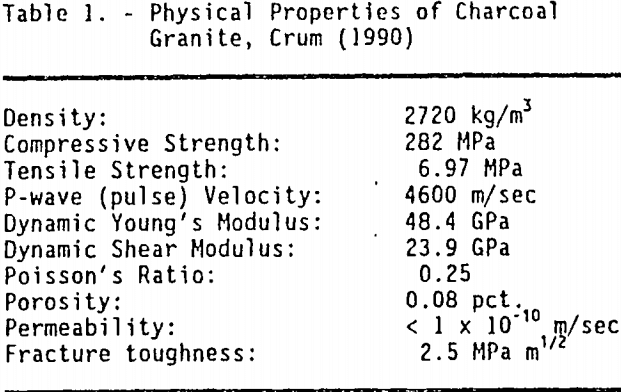
Careful consideration was exercised to select a rock sample for use in these tests. Except for one sample, all of the blocks used were cut from a single large block of St. Cloud gray granodiorite obtained from a quarry located near St. Cloud, MN. St. Cloud gray granodiorite is often referred to by its trade name, charcoal granite. Besides being relatively homogeneous, charcoal granite was also readily availability and massive in character. All of the test samples were fine grained and dark in color. Physical properties of charcoal granite were reported by Crum et al.(1990) and are listed in table 1. The other test sample was a block of oracle granite, obtained from a Bureau cooperative field site located near Casa Grande, AZ, where an in situ copper mining experiment is being conducted.
Test Summary
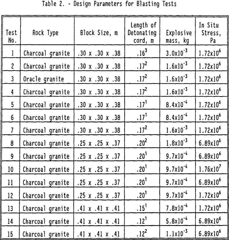
The various test parameters are summarized in table 2. Tests 8-12 were conducted at TerraTek and tests 14-15 were conducted at SAIC. To calculate the amount of explosive used in each test, the explosive contained in the detonating cord was added to the explosive in the EBW initiator. The explosive contained in the detonating cord represents the actual amount of PETN, rather than the nominal values designated by the manufacturer. All of the shots, with the exception of shot 7, were fully coupled. A quick-drying grout was used to completely fill each borehole.
Two of the tests at TerraTek, numbers 11 and 12, were vented to the atmosphere. Although they were fully coupled, they were not stemmed. Once the grout, upon addition, reached the top of the explosive column, no further grout was added. At the time these tests were conducted, it was believed that such venting would lower the long-term gas-pressure strain.
Results
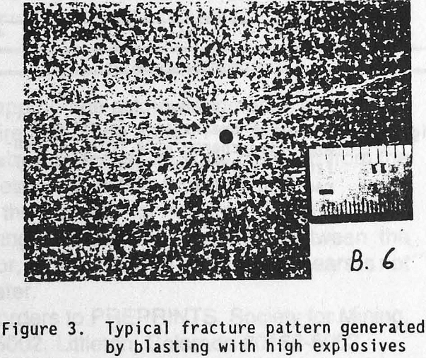
After the blocks were blasted, they were cut perpendicular to the borehole in the middle of where the explosive column once existed. Figure 3 shows a typical fracture pattern. The blocks were carefully inspected to determine if severe crushing or compaction existed around the borehole. Although numerous fractures were observed close to the borehole, there was no evidence that the borehole radius changed in any of the fifteen tests, including test 7, the uncoupled shot. Although the degree of damage near the borehole wall was not quantified, the grout surrounding the explosive column remained intact.
To assess the fracture network, the number of cracks intersecting concentric circles at .013 m (½-inch) intervals was counted. Dye penetrants were used but did not facilitate the crack counting. The results are shown in table 3, where the number of cracks is tabulated against the radial distance from the center of the borehole. Two characteristic trends were observed when examining the fracture patterns. First, in all cases, a dense zone of tight radial fractures existed around the borehole. These fractures extended out to 20 to 30 charge diameters, in agreement with the results of Spathis et al. (1987). By comparison with previous Bureau researchers, Olson et al. (1973) reported 9-10 charge diameters for tests in granite using C-4 (a military explosive), Siskind et al. (1973) reported 21-27.5 charge diameters for tests in shale using 60 pct dynamite, and Siskind and Fumanti (1974) reported 7 charge diameters for tests in granite using ANFO. The second characteristic trend observed was that in some of the cases, approximately 2 to 6 gas-driven fractures propagated out to the edge of the block.
These trends can be identified in figure 4, where the number of cracks is plotted versus radial distance for tests 8 and 15. In test 15 the number of cracks falls off quickly. In test 8, however, several cracks propagated out to the edge, past the largest radial distance for which cracks were counted. When the size of the block was increased sufficiently, the second trend was not observed and the dense zone of tight radial fractures around the borehole remained essentially unaffected.
In the case of block 3 (the granite block obtained from the Sacaton mine in Arizona) numerous blast-induced fractures could not be accurately counted due to preexisting cracks and the intergranular boundaries. The preexisting cracks or open joints, about .15 m (6 in) long, acted as free surfaces, and at least one radial crack opened upon intersecting a joint.
To verify that the number of cracks increases with increased explosive mass, the number of cracks at a radial distance of .051 m (2 in) was plotted against the amount of explosives used for all of the cases where the simulated in situ stress level was 1.72×10 6 Pa (250 psi). These results are shown in figure 5. The least squares fit through the points is also displayed. Although there is some scatter, the data supports the above hypothesis.
To determine the effect of in situ stress on the fracture pattern generated, the number and total length of cracks were plotted against stress for those tests using 1.6×10-³ kg detonating cord, and are shown in figures 6 and 7, respectively. In figure 6, the number of fractures at a radial distance of .051 m (25 hole diameters) was chosen to be representative of the results. The total crack length was determined by summing up the lengths of individual cracks at the same .013-m (½-in) intervals at which the number of cracks was determined and adjusted for any cracks which exceeded the .076-m (3-in) radial distance. Although there is considerable scatter in the data, especially at lower stress levels, the results are similar to the results for tests conducted in hydrostone and reported by Schatz (1987), where crack length of fractures showed some scatter at lower stress levels. Using an envelop of the data, increasing the stress level from 6.89×10 6 to 1.72×10 7 Pa (1000 to 2500 psi) reduces the number and length of cracks by about 33 pct.
Although blasting-induced permeability enhancement is of interest to this paper, no permeability measurements were made. The existing laboratory test procedures to measure the permeability of rock samples, as reported by Lewis and Tandanand (1974), is limited to about 9.9×10-²² m² (0.1 md). For rocks considerably less permeable than that, for example, granites with permeabilities of 9.9×10-²² m² (1 nd) and below, Brace et al. (1968) devised a transient flow test.
The Bureau was unable to perform transient tests, because the equipment needed to do them was not available. Because there has been no observed crushing near the borehole wall in any of the tests conducted by the Bureau (which might seal off cracks which are formed), it is assumed that the crack data obtained in the laboratory will be adequate to assess the feasibility of using high explosives to enhance permeability. The Bureau is investigating using computerized tomography techniques to determine lixiviant flow in the damaged zone closed to the borehole wall. Permeability tests will be performed in the field, where blasting and leaching tests will eventually be done.
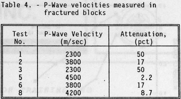
To corroborate the crack data, P-wave velocities were measured in some of the blocks (edge to edge, perpendicular to the borehole axis). The results are listed in table 4. The greatest attenuation in velocity, 50 pct, occurred in blocks 1 and 3 (6.5×10-³ kg and 3.2×10-³ kg detonating cord, respectively). The P-wave tests were not conclusive in defining the extent of rock damage. Further testing is needed to relate these results to the visually obtained data.
Conclusions
The Bureau of Mines conducted 15 single-hole tests to determine if high explosives could be effectively used to enhance permeability in hard-rock deposits for in situ mining. Two distinct trends were observed. High explosives generated a zone of numerous (e.g., 20) tight radial fractures that extended at least 20 to 30 explosive diameters. In situ stresses up to 1.76×10 7 Pa (2550 psi) were applied. The data appear to suggest that in situ stress influences the fracture density and the total overall length of cracks, but more data are needed to substantiate this conclusion. Increasing the in situ stress from 6.89×10 6 to 1.72×10 7 Pa (1000 to 2500 psi) reduced the fracture density and total overall length of cracks by approximately 33 pct. If the blocks were not large enough, gas-driven fractures were able to propagate to the edges of the blocks, but a zone of dense radial fractures was, nevertheless, still observed. To prevent fractures from propagating to the edges of blocks in single-hole tests under the conditions described in this paper, it is recommended that .41 m (16-in) cubes or larger blocks be used. The observed fracture patterns imply that a blast design including .25 m holes placed 12 m apart would be adequate to sufficiently fracture ore deposits for modified in situ mining down to 305 m.


