Table of Contents
Copper smelting practice has not changed much over the last century. Little attention has been paid to the gas-fired reverberatory furnace because it has traditionally represented only about 10 percent of the total cost of producing copper from its ores. However, the emphasis on air pollution control, fuel shortages, and costs have generated interest in alternative smelting practices. Electric furnace smelting to produce copper matte is among the leading contenders.
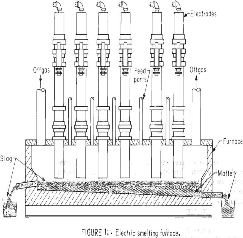
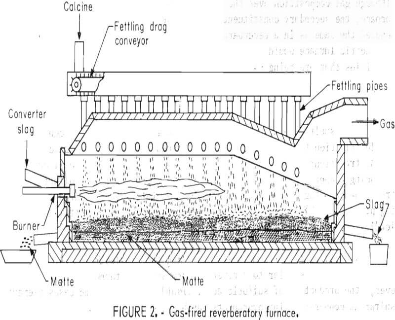
The configuration and materials handling for an electric smelting furnace (fig. 1) is quite similar to a reverberatory smelting furnace (fig. 2). However, the production of sulfuric acid, liquid SO2, or in some cases elemental sulfur as copper-smelting byproducts can be achieved at less expense due to
lower gas volumes and higher SO2 concentrations in the gases from an electric smelting furnace.
ASARCO Incorporated was interested in evaluating electric furnace smelting as a possible alternative for their custom smelter in Tacoma, Wash. The company entered a cooperative agreement with the Bureau of Mines to perform a series of smelting tests in an 800-kva electric furnace at the Bureau’s Albany Metallurgy Research Center (AMRC).
The investigation was designed to determine the feasibility of producing copper matte in an electric furnace from a feed similar to charge materials being smelted at ASARCO’s Tacoma smelter. The raw concentrates that are being processed at the Tacoma smelter come from many sources and present a wide variety of unique compositions. Consequently, several of the test plans emphasized procedures to determine the effects of charge composition, gas sweep, and furnace operating parameters on matte grade and the distribution of impurity elements in the furnace products.
Smelting Copper Concentrates in an 800-Kva Electric Furnace
Several combinations of chalcopyrite concentrates and smelter byproducts were blended by ASARCO to be processed in an electric arc furnace. The furnace charges were calculated to simulate the present and anticipated material flow through the cooperator’s smelter in Tacoma, Wash. Smelting parameters were changed during the test series to determine the effect of various electric-furnace smelting conditions on the compositions of the smelting products.
Materials Used for Smelting in the Electric Furnace
One concentrate from a single source and three blended concentrates were shipped to AMRC from the Tacoma smelter for the first seven smelting tests. The uncombined concentrate was particularly significant because it contained 11.4 wt-pct arsenic. The blended materials consisted of seven or eight different concentrates that are received by the custom smelter.
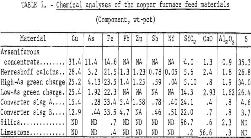
The concentrates and blends as they were received at AMRC were mixed with the appropriate amounts of converter slag and flux; furnace charges were calculated on the basis of individual concentrate and furnace byproduct analyses. The chemical analyses shown in table 1 were used for the material balances in smelting tests 1 through 6.
Additional furnace charges were blended at the Tacoma smelter for the last six smelting tests and some additions were made at AMRC. Feed compositions for the last six tests were based on chemical analyses of samples that were taken from the feeder belt during each smelting test.
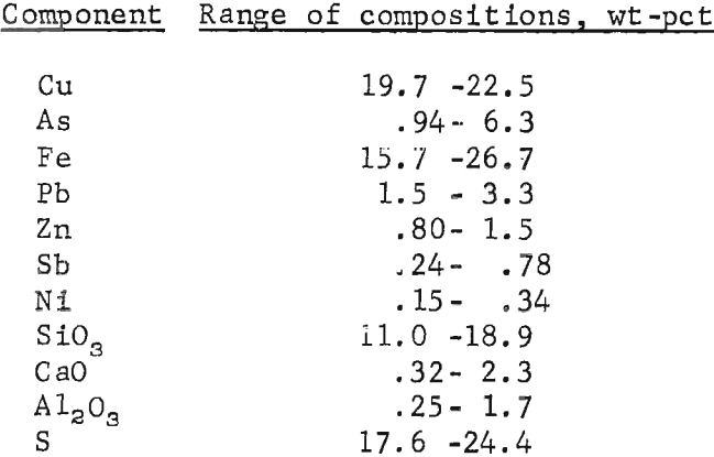
The feed materials for all tests included amounts of pulverized converter slag equivalent to the amounts of molten slag that return to ASARCO’s reverberatory furnaces,. Therefore, the predicted amount of iron reporting to the matte was equal to the iron in the converter slag that was being added. That parameter is necessary to maintain a balanced flow through the entire smelter and was adhered to throughout the investigation. Fourteen tests were made to smelt furnace charges containing the following components:
Equipment Used During Smelting Tests
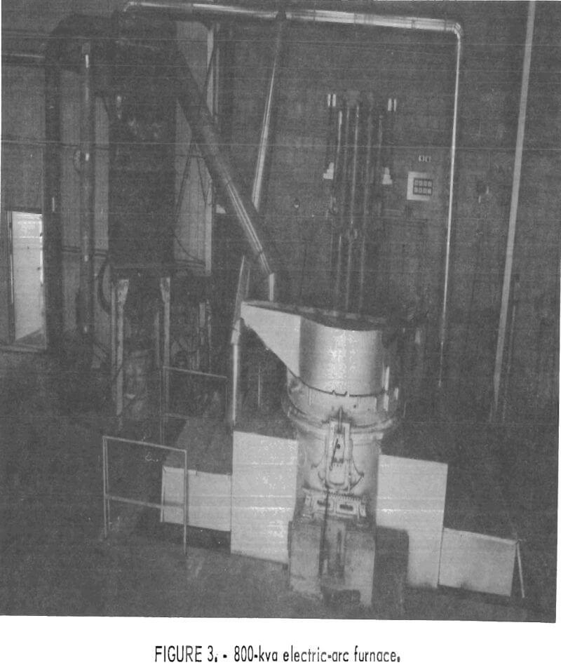
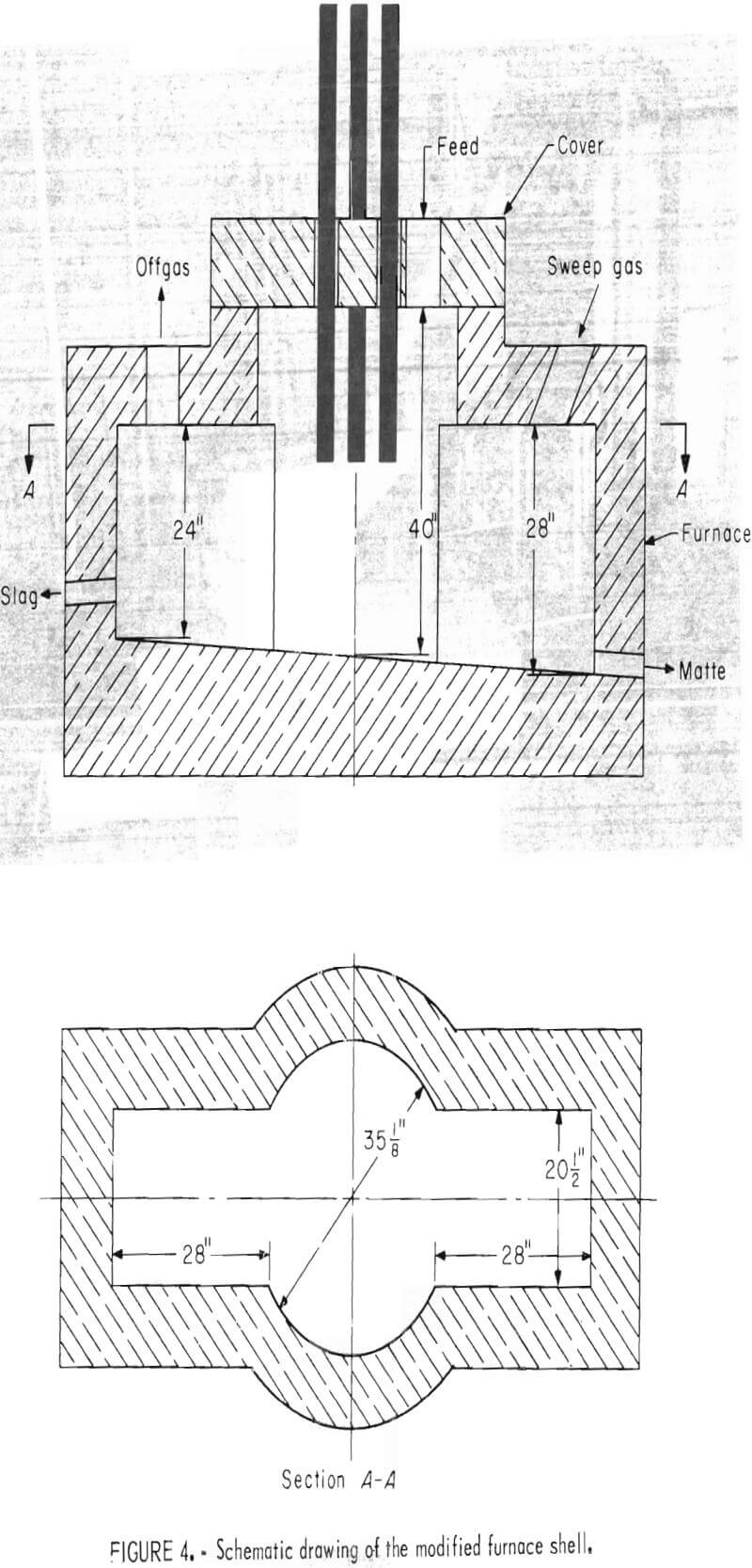
Figure 3 shows the 800-kva electric furnace that was used for this investigation. The furnace was powered through three 4-inch-diameter graphite electrodes that were positioned in a conventional “delta” configuration on 12-inch centers. A cylindrical furnace shell was modified to increase the furnace capacity, provide a quiescent zone by locating the tapholes away from the turbulent furnace delta, and more closely simulate the bath surface area to depth ratio of a production unit. Figure 4 is a schematic drawing of the modified furnace shell.
Magnesite bricks were used to line the bath portion of the furnace and chrome-magnesite bricks were used for the upper sidewalls. Alumina ram-mix was used to slope the furnace hearth and for the arched roofs over the rectangular furnace extensions. The hearth area was 14.3 square feet and the lined furnace could contain approximately 3,000 lb of molten bath.
The charge material was gravity fed through the furnace roof and the feed rates were controlled with a 4-inch-wide variable speed belt feeder. A stainless steel feed chute that extended (inside the furnace) from the roof line half way to the furnace hearth was installed for some smelting tests to protect the free-falling feed material from the smelting atmosphere.
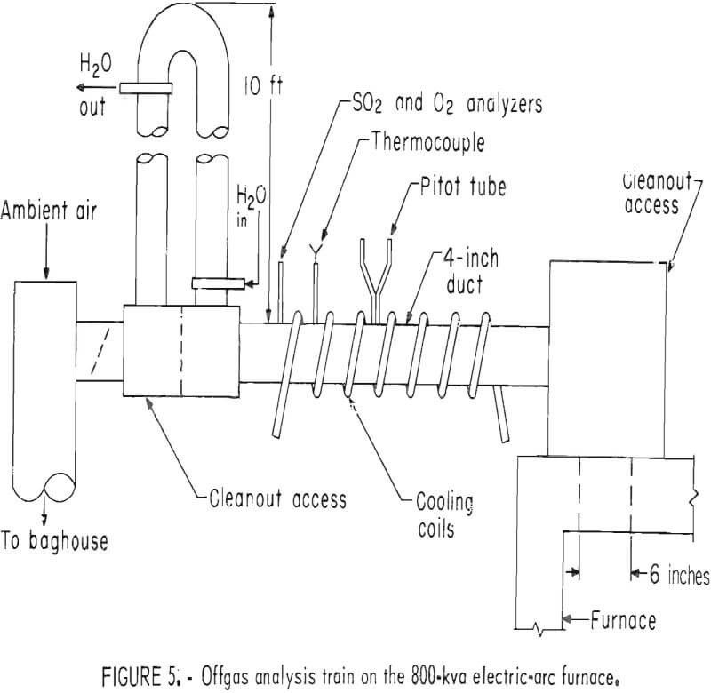
The small baghouse to the left of the furnace in figure 3 was installed to quantitatively collect the entrained fines from the furnace offgases. The baghouse was connected to the furnace by the offgas analyses train shown in figure 5. The offgas analyses train was equipped with an infrared gas analyzer to continuously monitor SO2 levels and a magnetic susceptibility oxygen analyzer that was used periodically during each test. After the smelting offgases had passed through the water-cooled tower, very little ambient air had to be added to keep the baghouse temperature below 200° C.
The plenum and tapping pit hoods that are connected to the furnace in figure 3 were evacuated by a 7,500-cfm fan that exhausted into a positive pressure cyclone and baghouse system. Sulfur dioxide was removed from the dust-free offgases in a countercurrent scrubber in which sodium carbonate solution percolated down through a packed bed.
Operating Procedures for the Smelting Tests
Smelting tests in the 800-kva electric furnace were between 7 and 9 hr long. The amount of charge that was smelted during each test ranged from 5,200 to 9,700 lb.
Before each smelting test, the furnace was loaded with approximately 1,000 lb of charge material and the initial charge was preheated to 1,000° C with a gas-fired burner that was inserted through the furnace sidewall. A smelting test was started by striking the initial arc across approximately 40 lb of metallic copper that had been placed on top of the starting bed in the electrode delta. The belt feeder was started as soon as the initial bed was molten and the material had started to flow the length of the furnace hearth. Care was taken to prevent superheating the bath and eroding the magnesite refractory under the electrode delta.
The smelting system usually equilibrated within 1 hr after the test was started. At that time, the feed rate and power input were matched to keep the surface of the bath molten. One exception was made when the test was designed to determine the effects of operating with a “cold top” over the bath except within the electrode delta.
Slag was tapped from the furnace approximately one-half hour after the smelting system had reached equilibrium. Alternate matte and slag taps were made during the remainder of a smelting test. Generally, about 1,200 lb of matte were poured at a time and the following tap contained about 700 lb of slag. The copper content (grade) of the matte was checked after each tap. A sample was taken from the tapping stream during the matte taps and the matte portion of the furnace bath was sampled after slag was tapped.
The offgas flow rate for each smelting test was regulated so that very little gas was escaping through the electrode ports into the plenum hood. Under these conditions the amount of ambient air being drafted into the smelting atmosphere was minimized and essentially all of the reaction offgases were being exhausted through the offgas analysis train. The offgas flow rates (calculated from temperatures and Pitot tube pressures) and SO2 contents were continuously monitored. Oxygen contents of the offgases were periodically measured during most of the smelting tests.
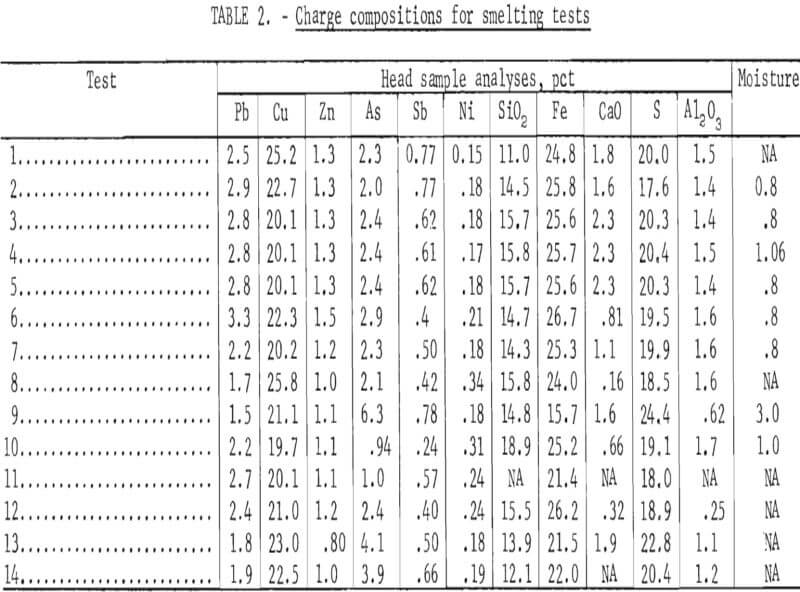
Fourteen smelting tests were run in the 800-kva electric furnace. Material balances and operating data were recorded from each test for comparisons based on related changes in charge compositions and smelting parameters. All of the blended charges were fluxed to produce slags containing 38 to 40 pct SiO2 and 4 to 6 pct CaO to provide the best resistivity and fluidity for electric furnace smelting. The charge compositions for the test series are summarized in table 2.
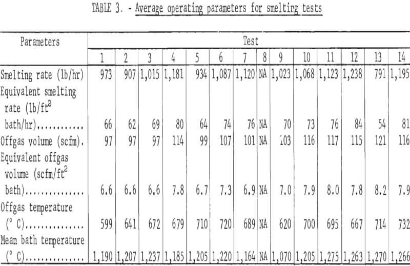
Smelting parameters were maintained to allow smooth furnace operation whenever possible. The feed rate, feed pipe length into the furnace, and air sweep over the furnace bath were changed independently to determine how the changes affected component distributions in the furnace products. Table 3 contains the smelting parameters for the test series. In tests 5 and 6, the charge feed pipe was extended about 20 inches into the furnace to determine its effect on mechanical dust losses, sulfur elimination, and arsenic distribution. The feed rate was lowered by about 50 pct (to 791 lb/hr) for test 13 to determine the effect of increased gas sweep per unit charge and greater retention time on the arsenic elimination and copper content of the slag.
Smelting test 8 represented the most radical deviation from normal operation. The test was run to measure heat losses from the furnace and determine the effect of ambient air on the arsenic and sulfur eliminations by blowing argon over the bath and determining the offgas compositions during that period. Grab samples of the entrained dusts were collected for X-ray diffraction analyses both with and without inert gas being introduced into the system. Because heat loss measurements were made by holding the furnace for extended periods without any power, no operating data were collected that could be com-pared with the other smelting tests.
Results of Smelting Tests
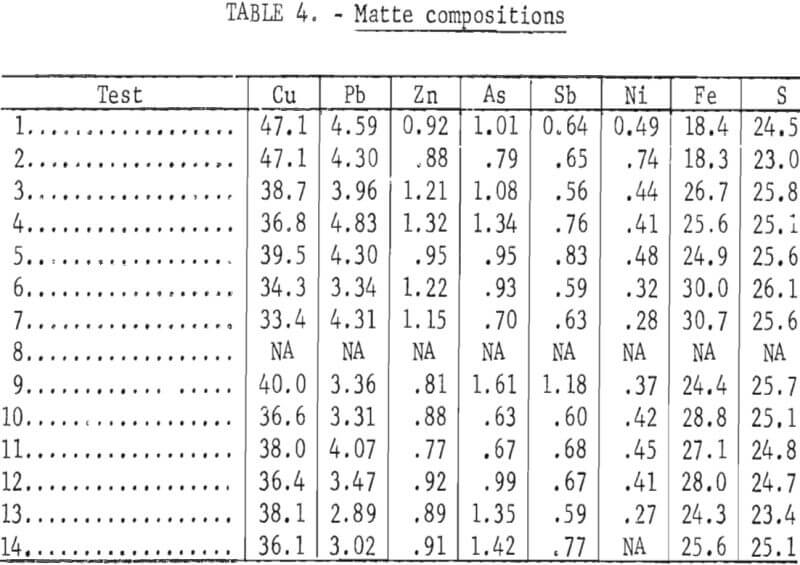
Smelting tests in the 800-kva electric furnace included as many as five matte taps that were generally followed by a slag tap. Matte that was tapped from the furnace usually contained some slag and vice versa. Therefore, the smelting products were carefully separated after cooling and each component was analyzed and its composition recorded separately- The analytical results reflected the inadvertent fluctuations in feed rates, bath temperatures, and other smelting parameters as well as the intentional changes that were made. All of the analytical data were compiled into the material balance sheets in appendix A. The total accountabilities for each component include accumulations of the sampling and analytical errors inherent to working with relatively large amounts of nonhomogenous products as well as some dust losses during the smelting tests.
The total weight that was recovered of each component was used to calculate the distribution of the component between matte, slag, and “process” dust that occurred in each test.
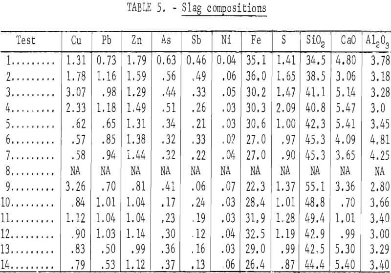
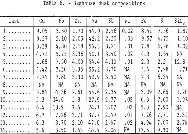
The composite analyses shown in tables 4, 5, and 6 are based on weighted averages of the values included in appendix A. These compositions relate more closely to the intentional changes in smelting parameters that were made during the test series.
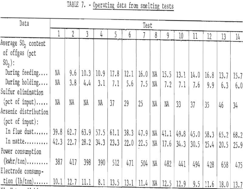
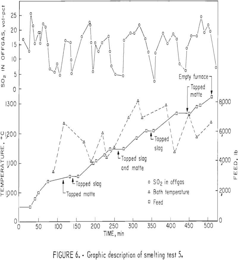
In addition to the general distribution of the charge constituents during electric furnace smelting, the investigation stressed the effect of smelting conditions on arsenic distribution and sulfur elimination. Figure 6 is a graphic description of smelting test 5 that typifies how each test was evaluated regarding the relationship between the furnace operation and offgas compositions. The rapid response that was exhibited by the SO2 monitoring system to the termination of feeding indicates the reliability of offgas data. Average bath temperatures were determined for table 3 by measuring the area under the curves (as shown for test 5 in fig. 6) and dividing by the total elapsed time. Table 7 summarizes the resultant operating data, related SO2 eliminations, and arsenic distributions.
After the offgas flow rate was balanced with the gases being evolved from the smelting reaction, the flow rate was approximately 100 scfm during each test. The offgas equivalent ranged from 8,400 to 13,455 scf/ton of charge depending on the smelting rate that occurred during a specific test.
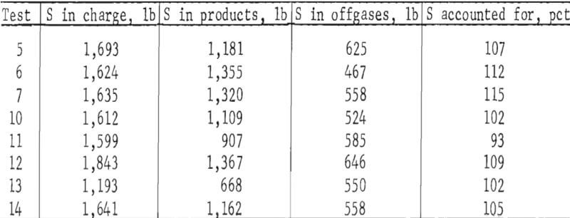
Incremental offgas flow rates and SO2 concentrations were used to calculate [(scf SO2/min) (time)] the sulfur eliminations that are included in table 7. The reliability of the values was checked as follows by calculating sulfur accountabilities for the tests from which sufficient data were available:
Flue samples of the entrained solids were collected only during smelting test 8. The first dust sample was taken from the offgas stream after the system had equilibrated under normal smelting conditions. Then a 25-scfm stream of argon was blown over the bath to prevent ambient air from entering the system and a second particulate sample was taken from the offgas stream. After the argon flow was stopped, the flow rate in the offgas stream was reduced from approximately 100 to 50 scfm and a third particulate sample was taken. X-ray diffraction analyses of the entrained fines identified As2O3 as the primary arsenic phase in all three samples, and traces of As2S2 were found in the samples that were taken while injecting inert gas and when the offgas flow rate was reduced. It is apparent that the elimination of arsenic is not dependent on ambient air being introduced during the smelting process. Arsenic analyses of the smelting products did not indicate any effect from the changes that were induced in the smelting environment,.
The power consumption data in table 7 were calculated from the power input during actual smelting and the associated time. In order to approximate a continuous operation, the power consumed while melting the furnace nest and during unavoidable delays was not included in the calculations. A bath temperature cooling curve was established from immersion thermocouple measurements that were taken with the power off during smelting test 8. However, the values that were collected could not be correlated with the operating power inputs or with the power levels that required to maintain bath temperatures under the same furnace conditions.
Discussion
The test results indicated that the matte grade (copper content) was primarily determined by the chemical compositions (Cu, Fe, S, and O) of the furnace charges. As shown in appendix A, the first matte that was tapped from the furnace in some tests was appreciably higher in copper content than matte from later taps. This was caused by the metallic copper plate that was used for startup and by some roasting of the initial charge while preheating the furnace. The two following smelting variables clearly influenced the matte grade:
- Matte grade was increased by increasing the gas sweep over the furnace bath as indicated by the offgas volume per ton of charge smelted.
- The matte grade was higher as the SiO2 contents of the furnace charges increased over the range from 11 to 19 pct.
There is some question as to whether the SiO2 content actually affects the matte grade or whether other conditions occurring simultaneously are responsible.
Heat is generated in the electric smelting furnace by current flowing through the molten slag. Consequently, the electrical properties of the slag are very important. The charges for the smelting tests were fluxed to produce slags containing from 38 to 40 pct SiO2. However, many of the charges were fluxed on the basis of predicted chemical compositions and sulfur eliminations. The resultant SiO2 contents ranged from less than 34 to over 55 pct. The wide range did not cause any serious operational problems, but slag with SiO2 contents over 43 pct were quite viscous and hard to tap while the slags that contained less than 35 pct SiO2 caused electrode-arc instability. The results indicated slags containing 36 to 42 pct SiO2 promote steady power conditions and fluid smelting products at normal operating temperatures.
Copper contents of the electric furnace slags ranged from 0.57 to 3.26 pct which is much higher than the 0.4 to 0.5 pct copper contained in the reverberatory slags from a commercial operation. Although the higher copper losses can be partially attributed to high slag viscosities, the furnace configuration and experimental practice were probably the principal factors contributing toward high copper slags. The turbulence that is characteristic of an electric smelting furnacec and the close proximity of the tapping holes to the furnace delta (fig. 4) caused excessive entrapment of matte prills in the electric furnace slags. Bath depths that were maintained in the 800-kva furnace made it necessary to tap too close to the slag-matte interface. Consequently, some matte was removed during slag taps and vice versa. The resultant mixing contributed to the high copper contents of the slags.
It was confirmed that relatively high concentrations of SO2 can be obtained in electric furnace offgases by controlling the volume of air flowing into the furnace. In the seven tests that included the best sulfur accountability data, a smelting rate o f 102 lb/ft²/hr produced an average of 11.3 pct SO2 in the offgases. It is anticipated that offgases containing 4 to 8 pct SO2 would be produced when smelting similar materials at slower rates in a commercial electric furnace.
The distributions of contained impurities and byproduct elements can be followed in appendix A. With the exception of arsenic which reports more readily to the copper matte, the distribution of impurities and byproduct elements in the electric furnace products appeared to be about the same as in a commercial reverberatory furnace.
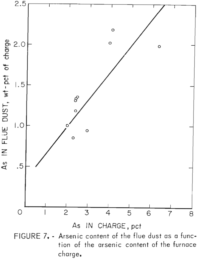
From 38.3 to 68.2 pct of the contained arsenic was eliminated by fuming and 1.5 to 11.8 pct was lost to the slag during the smelting process. Figure 7 shows that the amount of arsenic contained in the flue dust was directly proportional to the arsenic content of the furnace charge. Generally, the inverse was true for the amount of arsenic in the slag. Changes in offgas volumes and air sweep through the furnace did not have any appreciable effect on the arsenic distribution.
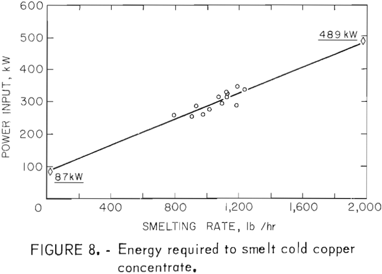
The power consumption data that are included in table 7 range from 387 to 658 kwhr/ton and average 466 kwhr/ton of solid charge smelted. Because the test values increased rapidly as the smelting rates were lowered and did not include all of the power that was used during an entire test, the total power consumed in each test was used to establish an equivalent value. The average power input for each test (total power/total time) was plotted against the respective smelting rate. Extrapolation of the relationship shown in figure 8 indicates that 87 kw is equal to the heat loss from the furnace and 489 kw would be required at a smelting rate of 2,000 lb/hr. By difference, the energy required for actual smelting was 402 kwhr/ton of solid charge. The experimental and calculated energy requirements agree well with the 440 kwhr/ton that is required to smelt cold copper concentrate in a commercial electric furnace with nominal heat losses.
Conclusions
Electric furnace smelting of copper concentrates is very similar to reverberatory furnace smelting of the same materials. Slags containing 36 to 42 pct SiO2 promote steady power conditions and matte grades that are compatible with established converting techniques. With the exception of arsenic which reports more readily to the copper matte, the distribution of impurity and byproduct elements is essentially the same as in a reverberatory furnace. The amount of arsenic contained in the flue dust is directly proportional to the arsenic content of the furnace charge and changes in air sweep through the furnace do not affect the arsenic distribution
Smelting in the electric furnace at a rate of 102 lb/ft²/hr with minimal ambient air entering the system produced an average of 11.3 pct SO2 in the offgases. Based on these results, offgases containing 4 to 8 pct SO2 would be produced when smelting similar materials at established rates in a commercial electric furnace.
