Table of Contents
Some explanation of methods of testing will be given before presenting the record of a series of physical tests of aluminum, other metals and alloys. The test-bars used, 12 inches long and ½ inch square, are cast in green sand, with chills bedded in such a way that the ends of the bar run against them. By splitting the ends of the bar the depth of chill can be measured. The chills being held in the mould 12 1/8 inches apart, the space between the end of the bar and the face of the chill, after both are alike cold, is the amount of shrinkage, and is recorded in thousandths of an inch per foot.
Autographic Recording Apparatus of Aluminium Testing: As bars of some materials shrink more than 1/8 inch per foot, the bearings for the ends of the bars under test are made of springs 12 inches apart, with sockets at their upper ends. Fig. 1, a.a. The bar tested is thus 12 inches long, whatever the actual length may be.
In transverse tests the stress is in the direction of the arrow b, causing the bar to bend. The stress is received on the steel receiver b, which with f is clasped to the bar, and prevents injury to the material of the bar at the point where the stress is applied. The center d of the bar moves exactly in accordance with the bend of the bar.
In order to make a record of the position of this center during the whole test, we clamp the cage b f to the center of the bar. Behind the bar is an arm connected to the cage at d, and the rear end g of this arm is fastened to a spring suspended from c, while the forward end of the arm carries a pencil e, which moves five times as far as the center of the bar. A parallel motion located between e and d (not shown in the drawing) causes the pencil e to travel in a vertical line. All bearings are springs to prevent wear or lost motion. Any motion of d, whether from a gradually applied stress, or from a blow, on b is exactly reproduced by the pencil e. A sheet of paper is held on a flat holder behind the pencil, and can be moved in the direction of the length of the bar, the pencil e bearing upon its surface.
Aluminium Weight-Testing Machine
We shall not, in this paper, describe our machines in detail. Those who wish a full illustrated description can procure from the United States Patent Office copies of patents Nos. 399,754 and 403,676. This is a single lever machine, in which by moving a weight out on a beam a gradually increasing stress is applied to the center d of the test-bar. The beam is not kept floating, as in ordinary testing-machines, but the center of the test-bar and the beam descend together.
The weight W is propelled by a steel cord, and another cord moves the paper which receives the autographic record one-quarter as fast as the weight. The weight and paper can be run either forward or backward. With a 50-pound weight the machine exerts a stress on d of from 0 to 600 pounds; with a 100-pound weight on; the beam double this stress can be applied. Fig. 1 shows a diagram made by this machine from a test-bar of cast-iron. The test-bar was clamped in the bearings a a, and the weight run back until it was over the fulcrum j, when no stress was exerted on the-test-bar,
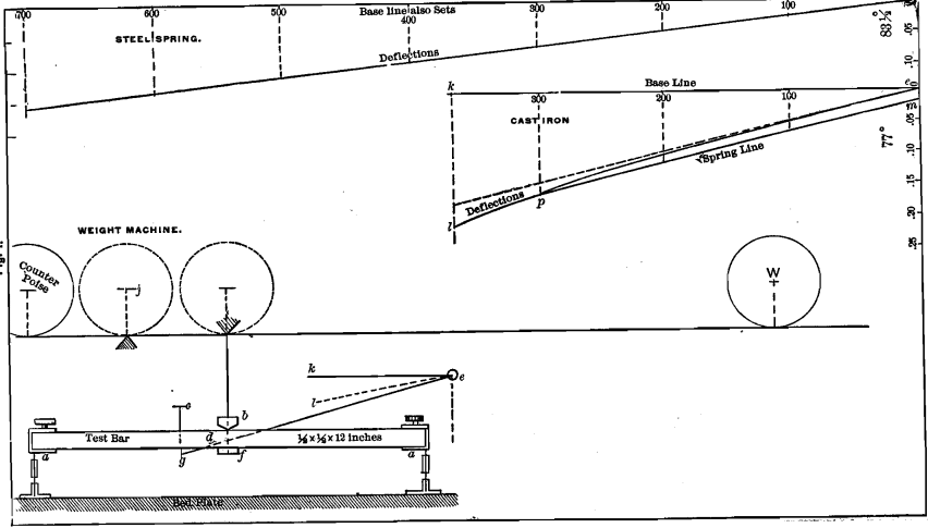
the counterpoise exactly balancing the machine, and the pencil, e, was consequently at the highest point. The paper was now moved along until the base-line k e was drawn. The cord then being attached to the paper-holder, the location of the pencil e was marked as zero (0).
As the weight is propelled forward, the increasing stress bends down the center d of the bar, carrying with it the pencil e. The forward motion of the paper and simultaneous downward movement of the pencil describe a line e l, diagonal to the base-line k e. By marking off, on the base-line, points corresponding to pounds of stress exerted, and on a perpendicular from the zero-point points corresponding to inches of deflection, we can tell at a glance how many pounds, and how much bending or strain, is represented by any point in the diagonal line or diagram. This is, therefore, a stress- strain diagram. If the test-bar is a perfect spring, the deflections are proportional to the weights, and whenever the stress is removed the pencil will come back to the base-line. Most materials bend, not in proportion to the stress exerted, but faster; and in such a case (illustrated by the diagram from cast-iron) the diagram is a curve. In this case when the stress reached 300 pounds the weight was run back to zero, and the pencil did not come back to the zero-line, but rested at m, because this iron, in its original condition, was not a perfect spring. Thus e m represents the amount of permanent set that the test-bar has taken in inches under 300 pounds stress. (To measure set or deflection on a diagram made by our machines, we use a scale with 20 divisions to the inch and call the reading hundredths-of an inch.) We now run the weight again to 300 pounds and a new diagram m p is recorded. If we run back to zero any number of times from the 300 point, the pencil will always traverse the line m p, showing that the cast-iron bar has become a perfect spring for all stresses less than 300 pounds. The ultimate strength cannot be influenced by repeated stresses, if each is less than this proof-stress.
The character of the metal has been changed, but if the weight is run beyond 300 pounds the instant it passes this point the original character of the metal again appears and the diagram is a continuation of the original one, and, taken as a whole, is exactly the same as it would have been if the stress had been continuously increased and not relieved at 300 pounds. In Fig. 1 the curve e p l should have been a continuous curve. The engraver has by mistake made a depression at p. The same mistake is made at e, in Fig. 2. All spring-lines from the same bar during one test (and perhaps through all tests) are parallel.
To show more clearly this change in the nature of a metal by work done upon it (which illustrates the effect of forging, rolling and wire-
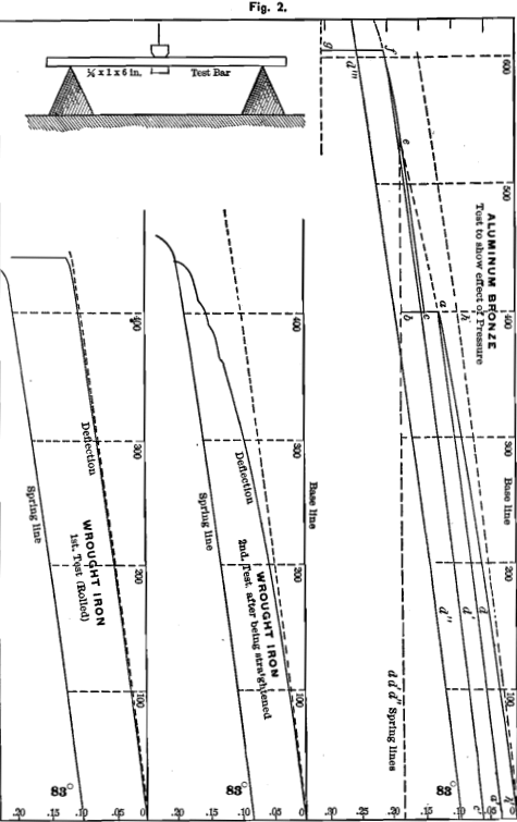
drawing), we produce in Fig. 2 a diagram from aluminum-bronze. Here we ran the weight to 400 pounds and then made a spring-line a a’. When we again reached 400 we knew that if we should continue moving the weight out on the beam the line of the original diagram h’ a would be continued to e, but we stopped at 400 and bore down on the beam with one hand, deflecting the test-bar to b. On allowing the bar to recover it came back only to c. We then ran the weight from c out beyond 400 and found the diagram to be a spring-line until it reached e, which we found to lie on a line running parallel to the base-line and passing through b.
After passing this point e the original diagram, was resumed and continued until f. We then made a new spring-line c’ f. On again reaching f we again bore down to g and the bar returned to d'”. We then ran the machine back to the zero-line and made the spring-line d” d”‘, and on pushing the weight beyond d”‘ we found the spring-line continued until it intersected the ordinate through g, when the original diagram was again resumed.
We conclude from our observations that for gradually applied stress or a dead load a bar is a perfect spring for all weights less than the greatest proof-load that has been applied, unless the proof-load was very near the stress which would cause the bar to give way, in which case the deflection of the second diagram, just before reaching the proof-stress, may exceed that of the first diagram and the lines may not meet.
The set which each of the bars shown in Fig. 2 has taken, differs from the set taken by the cast-iron of Fig. 1. The set in the cast- iron is caused by a change in the shape of the molecules of the metal. The set in the bars of Fig. 2 is caused by the flow or sliding on each other of the molecules of the metal which become partially viscous when a certain stress has been exceeded. Until flow sets in the speed with which the weight is run out on the beam of the machine has little or no influence upon the form of the diagram. When, however, the bar begins to bend rapidly it is difficult to refrain from sympathy with the specimen and to slow up, which allows the metal to flow still more and thus produces a steeper curve. This is seen in Fig. 2 in the test of wrought-iron after straightening.
Most metals which take a set as the stress is increased, but which do not flow, probably take set, however small may be the stress applied, though the amount of set may be too small to be measured. Metals which can take no set, but which flow when a given stress is exceeded, may form a perfect spring and therefore take no set up to the commencement of flow.
It will be seen that the spring-lines of cast-iron and of many metals are curves, and yet the fact that the pencil always traverses the same line proves it to be a spring-line, though the peculiar
internal spring of the atoms of the metal does not cause the deflections to be exactly proportional to the stress.
Good illustrations of this are the diagrams taken from a bar of rolled wrought-iron, Fig. 2. The bar was a perfect spring for all weights less than 400 pounds. After that it took a slight set and at about 430 pounds gave way completely, the metal exhibiting viscosity to a remarkable degree. Reversing the machine as quickly as possible we made a spring-line. It will be noticed that the bar in this case gave way at an earlier point than under the first application of stress.
We now straighten the bar and test it again. The bar does not act at all as it did during the first test. It takes set at each increment of stress and after 300 pounds it flows rapidly, but the metal does not give way suddenly at 430 as before. We take a spring-line and notice that it passes the former strength. This often occurs and is due not to any rest given the bar but to the work done on the bar.
Aluminium Impact-Testing Machine
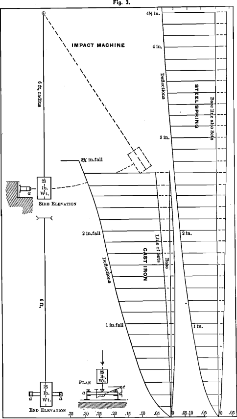
In this machine, Fig. 3, the test-bar is fixed in the same bearings of the same autographic recorder, as was already described ; the same pencil and paper are used, and all conditions are alike in both machines, except that, in the impact machine, the stress at the center of the bar is a blow from a 25- pound weight swinging on a radius of six feet. The paper is moved ahead about 3/16 in. after each stroke to remove the record of the stroke just made. The first blow is struck with 1/8-in. fall, and each succeeding stroke has 1/8 in. more fall than the preceding. The pencil records deflection and set and also the vibration of the bar.
We show in Fig. 3 an impact diagram from the same cast of cast-iron as the bar of Fig. 1. Gray cast-iron takes set at each blow, and often the set increases more rapidly as the point of fracture is approached.
Much of what we have said regarding weight-diagrams applies to impact-diagrams also. If the test-bar is a perfect spring, the set-line will coincide with the baseline. If a material is tested with a certain number of blows and flow has not begun, and a certain amount of set has been taken and the test is repeated from the beginning, no set will be taken until the last blow of the previous test is reached, for the bar is a perfect spring for all blows less than the proof-blow. This is especially true of bars that have been rolled down to the ½-in. square, provided they have not been bent and straightened previously.
The impact-diagrams shown in Fig. 4 are from a test-bar cut from the same rolled bar as the bar tested by weight, the record of which we had in Fig. 2. It takes no set until after a 2-inch fall. If we had stopped at 1 7/8 in. and had repeated the test, all diagrams
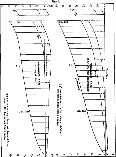
up to this point would have been alike, for the bar, up to the 2-inch fall, is a perfect spring. When we reach a blow that causes the metal to flow, each blow simply forces the bar down more and more, adding to the set and total bend; beyond this point we find the effect of the blows to show only in the sets.
We took another bar cut from the same piece and struck it two blows from a 3-in. fall; and we give the record at the top of the former record in Fig. 4. We now straightened each of these bars and repeated each test. The whole character of the bars had changed. Impact shows this change more fully than weight. The bars took set at each blow.
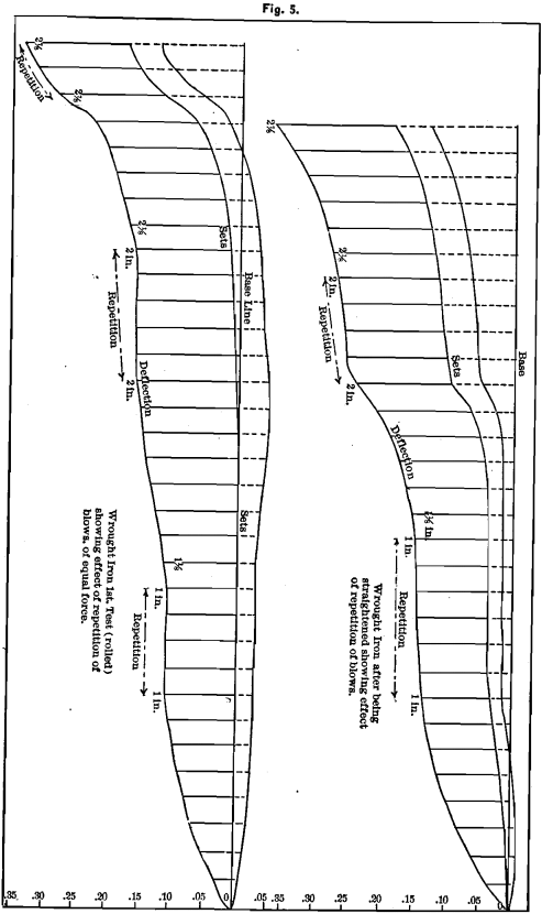
To observe the effect of a repetition of the same blow, we cut from the same piece of wrought-iron another test-bar which we tested, as before, up to a 1-in. fall, and then repeated this blow four times. The lines recording deflection, set and vibration, as shown in Fig. 5, are all parallel, showing no effect on the strength of the bar.
The regular blows were then struck up to a 2-in. fall, when the metal began to flow. Five repetitions of this blow depressed each of the lines of the diagram at each blow. This is much more apparent in the repetition of the 2 7/8-in. blow. The bar was now straightened and tested again, when it was found that each blow, whether a repetition or not, depressed all lines of the diagram.
Before flow has set in in such metals as we have just considered, and in many cast metals even after set has been given to the bar, a repetition of the same blow does not seem to diminish the strength of the bar.
The question of crystallization from repeated blows cannot be raised in any ordinary test. In our tests the blow is prevented from affecting the material at the surface of the bar. When repeated blows are given to a bar by a sledge on the face of the metal, each blow may develop the same force, but because of the effect of the blows upon the crystals of the metal at the point of contact, the metal is finally wedged apart. Such is not a legitimate impact-test. To compare weight and impact, we should compare bars which are of exactly the same constitution. As, for example, diagrams from two test-bars cut from the same straight rolled bar of ingot-iron or wrought-iron, or two exactly similar cast bars poured from the same ladle of metal. Or, take two pieces of wood ½-in. square, cut from adjacent places in a board. Take the breaking or yielding points of any pair of such bars, one tested by weight and the other by impact, and compare sets, deflection, vibration, weight and inch- pounds shown, and we shall see that the effect of impact cannot be deduced from any data obtained from the weight-diagram or vice versa. Each metal tested has marked peculiarities of its own.
By striking each specimen a blow from 1/8-in. up to the blow which causes it to give way, all are treated alike and the records are relative and comparable.
The new conditions presented by the results of our tests necessitate some new definitions for use in the explanation and comparison of our diagrams.
Rigidity or stiffness is the ability of a material to withstand stress and retain its original form. It is perfect when any stress that can be applied will not cause the material to change form. The diagram of a perfectly rigid bar would exactly follow the base-line. No rigidity would cause the form of a material to change without limit on the least application of stress. The diagram of no rigidity is a straight line perpendicular to the base-line at the zero-point. It is the abscissa on which changes of shape or the amount of strain are measured. The diagram of rigidity will be a line starting from the zero point and lying diagonally between the ordinate (baseline) and abscissa, which meet in a right angle at the zero point.
The measure of rigidity is the angle that the line or diagram of rigidity makes with the abscissa. It is called the rigidity angle.
In all diagrams made by our weight-machines the scale on the ordinate is either 50 or 25 or 16.66 millimeters for each 100 pounds, the scale being selected which will show the qualities of the metal to the best advantage.
The scale of deflections on the abscissa never varies, but is always multiplied by five to make the divisions easily seen and to make the error five times less.
All rigidity angles are reduced to the 25 millimeter standard and marked in degrees.
To reduce from the 50 to the 25 mm. scale take the difference between the angle and 90° and subtract this difference from the rigidity angle recorded. The resulting angle will be the rigidity angle for a 25 mm. scale.
For example, the angle of the diagram for cast-iron for a 50 mm. scale is 83° ; for a 25 mm. scale it would be 76°.
For the half-inch square steel spring the angle for a 50 mm. scale is 86¼° ; for the 25 mm. scale it would be 82½°.
Aluminium VS Rigidity, Hardness, Brittleness and Temper
Not only are some materials more rigid than others, but by alloying metals of low rigidity a compound may be produced which shall have a high rigidity. Rigidity is a structural property of matter and is not due to hardness.
With the sample of tool-steel from which our diagrams were made, the rigidity is the same whatever be the temper or the hardness.
When given a dark-blue spring-temper it withstood various applications of stress both by weight and impact up to 800 pounds and up to a 5-inch fall without any effect upon the strength or shape of the bar. The bar was then hardened as much as possible and tested by weight to 400 pounds when it broke. The rigidity of the hardened steel was exactly the same as when blue. In both states the steel had the same bend and therefore the same elasticity up to 400 pounds, and yet the hard steel was brittle compared with the blue steel. We may properly say, then, that a metal need not be rigid to be brittle, nor does varying brittleness involve necessarily varying rigidity. Rigidity is not an element of strength or weakness, but it is a very important element in a structural material. It cannot be determined by the ultimate strength or by the total deflection, but only by making a spring-line and measuring the angle of rigidity.
Stress is measured on the ordinate or base-line from the zero-point in pounds avoirdupois for the weight-machine, and for the impact-machine by the number of the blows or by the value of each blow in inch-pounds.
Deflection is the distance (at right angles from the base-line) traversed by the center of the bar under any given stress. It is measured in hundredths of an inch from the base-line, the scale being laid off on the abscissa passing through the zero-point.
The stress diagram may be a straight line if the deflections are proportional to the stresses (Hook’s law), or a curve if the deflections increase more rapidly than the stresses. The diagram may conform to Hook’s law for a certain distance and afterwards become a curve. The point where proportionality ceases is usually called the limit of elasticity. It is the limit of perfect elasticity, but a better term for it is the limit of proportionality.
Aluminium Elasticity
Elasticity is the property by virtue of which a body tends to regain its original volume or shape after it has been distorted. Elasticity is perfect or imperfect according as volume or shape is wholly or only partially regained. Elasticity of shape is the only elasticity considered in the testing of materials of construction, and in our tests only so far as it relates to the recovery of the central point in a test-bar one-half inch square and 12 inches long, supported at the ends and subjected to stress applied at the center in a direction at right angles to the length.
The measure of elasticity is the distance that the center of the test-bar moves towards regaining its original position on the base-line when the stress is removed.
The length of this line is given in hundredths of an inch, and is measured on the zero (or a parallel) abscissa. If the center of the bar returns to the base-line, the bar is perfectly elastic, and the diagram will generally be a straight line. In such a case the measures of elasticity and deflection are the same.
We can call the measure of elasticity elastic deflection.
For convenience we shall call the straight line conforming to Hook’s law a spring-line, as we denote the rigidity by the angle this line makes with the zero abscissa.
When the deflection is not proportional to the stresses, the additional deflection will not be recovered when the stress is removed. Such part of the deflection as is recovered is the elastic deflection, and the portion not recovered we may call set deflection or permanent set, or simply set.
To divide the total deflection, as produced by the weight-machine, into elastic and set deflection, we proceed as already described, viz.:
When we think that we have applied nearly as much stress as the bar will stand, we run the machine back to zero. If the bar has received any set the pencil will not come back to the zero of deflection, although it rests on the abscissa marking the zero of stress at a distance from the ordinate equal to the total permanent set.
If we now run the machine forward we shall describe a new stress- diagram, in which the deflections are proportional to the stresses, and it is therefore a spring-line, and its angle is the angle of rigidity. If now we lay off a line parallel to this spring-line and tangent to the original diagram at its zero-point we can see that between the base-line and this plotted spring-line all deflections are elastic deflections, and that between this spring-line and the original diagram all deflections are set deflections.
From the fact that it took the same stress to produce the diagram that consisted of both elastic and set deflections, and that which consisted of elastic deflections alone, it is evident that it takes no more force to produce both elastic and set deflection during an original test of a bar than it takes to produce only elastic deflection during a subsequent test. The bar has not necessarily been strengthened (although this is generally the case), nor has it become more rigid, for its rigidity angle is always the same, whether it has received 100 or 400 pounds stress, or whether the test was the first or was made after straightening; but up to the proof-stress it will take no set, and has only elastic deflection.
Aluminium Resilience
The definitions of this term, as given by various writers on the strength of materials, cover the idea of the work that can be done by a body, which has not taken set, in recovering its original form after stress has been removed ; in other words, the work done in producing elastic deflection.
Some writers say that the area of the diagram bounded by the base-line, the spring-line and the abscissa, measuring elastic deflection at the point of greatest stress (i.e., one-half total stress multiplied by elastic deflection), represents the total resilience. Some even multiply one-half stress by the total deflection in cases where set has been taken, as for example, in tests of cast-iron. All these writers seem to consider that the length of the line measuring elastic deflection depends upon the stress exerted to produce this deflection. For this reason we have endeavored to give a definition of elasticity that shall be entirely independent of the stress that produces the elastic deflection.
We doubt the advisability of using the term resilience in a general way, for, although elastic deflection is proportional to the stress in each given material, yet the elastic deflection for different materials is not the same for equal stresses.
Still greater difficulty arises when we endeavor to calculate the resilience shown by a diagram from the impact-machine. When
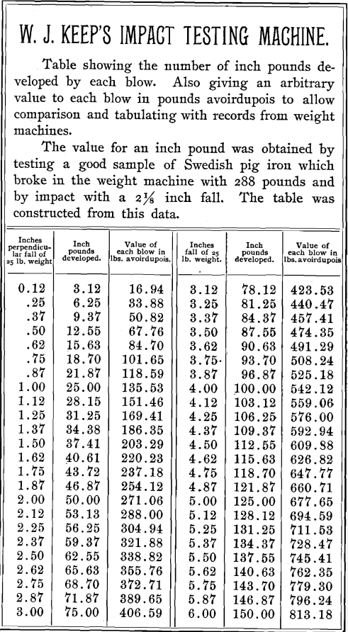
the products of two sets of numbers are the same, the mechanical results may not be the same. Hence, if we wish to compare results of tests of impact-machines, we must construct the machines exactly alike in main features. We use, for instance, a 25-pound hammer and swing it on a 6-feet radius, simply because we have selected these proportions—at first arbitrarily—but now because so much work has been done with this machine. A 25-pound weight multiplied by a 5-inch fall gives 125 inch-pounds. A 5-pound weight falling 25 inches gives a product, also, of 125 inch-pounds, as in the first case, but the effect upon the test-bar is not at all the same.
Comparative Bar Elasticity Under Stress by Dead Weight & Live Load
By examining diagrams from both the weight and impact-machines, we find that a test-bar is generally more elastic under a blow than under a stress gradually applied.
It is not correct to say that equal deflections represent equal impact-stresses; for we have already shown that elastic deflection is not dependent on the amount of stress, but on the character of the material.
If we examine a large number of diagrams from such a material as cast-iron, we shall find that some will stand a greater and some a less number of blows, as compared with the stress which caused fracture by the weight-machine; but in all cases it will be found that the elasticity is greater under impact than under weight.
In impact-diagrams the diagram of sets lies next to the base-line and the diagram of total deflection outside this line of sets.
The measure of elasticity is the distance between these two diagrams. The measure of sets is the distance between the base-line and the diagram of sets.
On the right-hand side of the diagram of sets is a diagram showing the vibration of the bar, and the measure of vibration is the distance between the diagram of vibration and that of sets.
In the impact-diagram, when the bar is a perfect spring, there will be no set, and the diagram of sets will, therefore, coincide with the base-line.
For the present, until further investigation shall suggest a better means of comparison, we give in Fig. 6 a table prepared by giving an arbitrary value to an inch-pound.
Proportions of the Test-Bar
Testing bars of the same material, but of different dimensions, brings to light the fact that having tested one bar of a material the data thus obtained cannot be used (with present formulae) to correctly calculate the strength of bars of
other dimensions. It is generally understood that the transverse strength is directly as the breadth, and as the square of the depth, and inversely as the length.
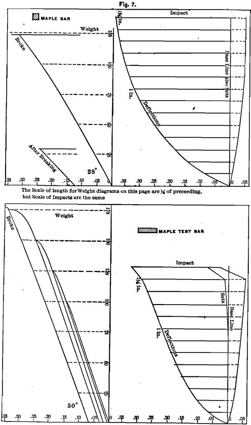
If this be true, a bar 6 inches long, ¼ inch deep and 1 inch wide (see Fig. 2) should have the same strength, and should make the same diagram as a bar ½ inch square and 1 foot long. The diagrams from maple-bars of the dimensions just mentioned, given in Fig. 7, show that the above proposition does not hold. In the tests reported in other parts of this paper, we have in several cases given diagrams from bars of both the above proportions, which show the same thing.
It is not, therefore, possible to reduce area to any given standard; as, for example, to one square inch cross-section of test-bar, if a bar of another section has been tested, or to a standard length if any other than such standard length has been used in testing. We, therefore, take a bar ½ inch square and 1 foot long and give all results as they are recorded without any reduction. This is, in the main, necessary; for there is no way by which we can express deflection, elasticity, set, rigidity or hardness, etc., as so much per square inch sectional area, or so much per pound.
The only way is to consider all these relatively. To make such relative comparison all dimensions of bars, all details of procedure, and all machines, must be exactly similar, and all records must be the actual results of the tests of these bars.
This is what constitutes “ Keep’s Tests.”
After the question of ultimate strength is decided, ability to withstand stress, without taking set, is the measure of usefulness for materials as ordinarily used.—To be fit for structural purposes, a material should be able to bear, without change of form, the stress to which it is subjected. To do this, it must be either perfectly rigid or perfectly elastic. In any construction, if any part remains out of shape after stress is removed, such distortion will either throw too much stress on some other part and thus imperil the structure, or (in such a case as that of an instrumental application, for example, of an engineer’s transit), throw all parts out of adjustment.
In boiler-plates, extensibility before fracture is no doubt of great advantage. This is true of other materials under certain conditions. To determine what can be done with a metal, it is important to know all of its physical characteristics.
PHYSICAL TESTS OF METALS AND ALLOYS
We intend, not to discuss generally the physical properties of the metals here considered, but only to present such new facts as our tests have revealed.
Generally, we have cast with our square test-bar a flat bar 1 inch wide and 1/10 inch thick. Both bars are cast in moulds 12 1/8 inches long.

The Shrinkage is the difference in length between the mould and the bar when cold, and our records are expressed in hundredths of an inch of shrinkage per foot of length.
As a general thing, the square bar and the thin companion-bar do not shrink alike. The difference in shrinkage of these two bars exhibits many peculiarities of the metal. Generally, a greater shrinkage in the thin bar indicates that the cooling effect of the mould exerts a decided influence on the castings; in other words, that the metal has a tendency to chill, and vice versa.
In cast-iron, if the shrinkage of the thin bar is less than that of the square bar, the iron is not likely to take a chill, and vice versa.

Hardness is determined with one of Professor Turner’s machines, and the record is the weight in grammes that causes a cutting diamond to make a standard scratch on a polished part of the test-bar.
Since the estimation of the standard scratch is, to some extent, a matter of judgment, too much importance should not be attached to a small difference in the recorded hardness of specimens.
It is safe, however, with such allowance, to compare the results obtained by one observer. Hence, the records of hardness published in our various papers can be compared with reasonable confidence.
Lead
Shrinkage, for the square bar, 0.113, for the flat bar, 0.101 ; hardness, 1 or 1.5.
As soon as the test-bar receives stress, the metal flows so rapidly that it is difficult to determine many of its characteristics. No

proportionality. Ultimate strength may be estimated at 10 pounds ; total deflection before the bar wholly gives away, about 0.04; elasticity, 0.02; set from flow, 0.02; rigidity, 16°. The impact-test reveals nothing.
The spring-line is considerably curved.
This sample of lead was taken from tea-chests, and melted but once, and is therefore as soft and pure as commercial lead will generally be found to be.
Tin
This metal, like lead, shows a strong tendency to flow. In such diagrams, the appearance of proportionality at the beginning of the diagram must be set aside.
Shrinkage, for the square bar, 0.053, for the flat bar, 0.051 ; hardness, 2; ultimate strength, about 20 pounds ; total deflection, about 0.09 (due almost wholly to flow, and therefore not definite, as more or less time would have changed it); elasticity 0.015 ; rigidity, 66°. The impact-test shows nothing of interest.
The spring-line is considerably curved.
Antimony
This metal solidifies in flat crystals, with the cleavage across the bar, which causes the metal to be very weak under transverse stress.
Shrinkage, for the square bar, 0.0.68, for the flat bar, 0.070; hardness, 16; ultimate strength, 31 pounds; proportionality ceases at about 12 pounds; total.deflection, 0.045 (of which 0.03 is elasticity and 0.015 permanent set); rigidity, 63°.
We did not test by impact.
In grinding on an emery-wheel it heated very little. This property may be one of the reasons for its being introduced into most anti-friction metallic compounds.
Zinc
Much depends upon the handling of zinc in melting, and much upon its purity. We show diagrams of two casts. One made
by an expert brass-founder, care being taken to prevent oxidation; and the second, from another lot of metal, melted in contact with the air. The crystallization of the latter is much coarser.
The shrinkage of the square unoxidized bar is 0.148 ; of the flat, 0.164; hardness, 6; ultimate strength, about 50 lbs.; proportionality ceases at about 30 lbs.; total deflection, 0.055; elasticity, 0.03; permanent set, 0.025; rigidity, 75°.
The impact-test does not possess any interest, nor does the diagram from the oxidized metal. The shrinkage of the latter was 0.189 for the square, and 0.165 for the flat bar.
Copper
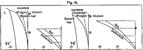
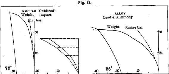
Copper is a difficult metal to form into castings from a peculiar tendency to swell after the mould is full, and from its rapid oxidation when in a molten condition. We procured the best commercial lake copper, and had our test-bars made by a brass-founder with the greatest care. The diagram, Fig. 11, shows that the metal flows as soon as stress is applied. Shrinkage, for the square bar, 0.248, for the flat, 0.223; hardness, 12; ultimate strength, about 60 lbs.; no proportionality; total deflection, 0.105 ; elasticity, 0.04; permanent set, 0.065; rigidity, 71°. The spring-line is a curve.
A cast, which we made with no care to prevent oxidation, gave shrinkage for square bars, 0.23; hardness, 14; ultimate strength, 50 lbs.; elasticity, 0.03; set, 0.06; deflection, 0.09; rigidity, 74°. Mr. H. A. Tucker found the tensile strength of this last metal to be 9154 lbs. per square inch, with elongation 4 per cent, in 1 inch. In Fig. 13 we give diagrams of this metal from bars ¼ x 1 x 6 inches in size.
ALLOYS OF THE PRECEDING METALS
Lead and Tin
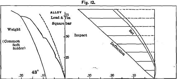
These were taken in equal parts by weight, forming common soft solder. This alloy has a lower melting-point than
either of the metals, and, like many other alloys, differs in every respect from its constituents. Lead has a shrinkage of 0.113, and tin of 0.053; but the alloy has 0.047 for the square, and 0.043 for the flat bar. It has twice the combined strength of both. Its hardness is 2; ultimate strength, 75 lbs.; no proportionality; total deflection, 0.18; elasticity, 0.11 ; set, 0.07 ; rigidity, 43°. The impact-diagram possesses considerable interest, especially as the bar takes no set with 1/8-inch fall, and shows considerable vibration.
Lead and Antimony
The latter metal is often used to harden lead. About 5 per cent, of it is used in this alloy.
It has a shrinkage of 0.064 for the square bar, and 0.063 for the flat, being less than that of either of the metals used. This is remarkable, as showing the small percentage of antimony necessary to take the shrinkage out of lead. Its hardness is 4, and its strength about twice that of antimony and six times that of lead, ultimate strength being 50 pounds. The diagram starts off in a peculiar manner, and yet we should wish to make other tests before stating
that proportionality did not cease until 20 pounds. Deflection is about 0.18; elasticity, 0.09; set, 0.09; rigidity, 26°.
Copper and Zinc
Five parts of copper and 4 parts of zinc. This is common brass which is a very indefinite term, on account of the varying proportions necessary to produce a given quality of brass due to the varying quality of each metal. In compounding brass it is sought to use the greatest possible quantity of zinc, so as to cheapen the alloy.
Often, by using a brand of zinc costing a cent more per pound, it is possible to use very much less copper and not injure the quality of the brass.
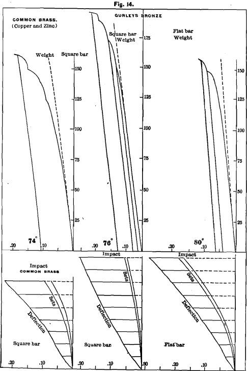
In this case we used the same copper and zinc as that from which we have shown tests. The diagrams in Fig. 14 show as remarkable results as any of the preceding alloys. The strength is three times that of either of the combined metals. The hardness is 10; the shrinkage, about the mean between that of copper and zinc, being 0.190 for the square, and 0.191 for the flat bar; ultimate strength, about 150 lbs.; proportionality, about 35; deflection, 0.15; elasticity, 0.08; set, 0.07 ; rigidity, 74°.
Gurley’s Bronze
This is composed of 16 parts of copper, 1 of tin, 1 of zinc and ½ of lead. It is used by Messrs. W. & L. E. Gurley, of Troy, N. Y., for the frame-work of their engineers’ transit instruments.
The bars tested were cast from the same pot from which frames were being poured. This alloy is remarkable when compared with the tests of the metals of which it is composed and with the record from brass bars. The ultimate strength is 200 pounds; proportionality continues until above 110 pounds; deflection is 0.15; elasticity, 0.10; set, 0.05; rigidity, 76°; hardness, 24. The ductility of this alloy is very great. Under impact-test it does not receive set until the ¼-inch fall, which is more severe treatment than any surveying instrument is likely to receive. The shrinkage is low, being, for the square bar, 0.177. We append diagrams from a bar ¼ inch thick, 1 inch wide and 6 inches long.
We sent bars for tensile test to Mr. H. A. Tucker, who reports its tensile strength 41,114 pounds per square inch ; elongation, 27 per cent, in 1 inch ; sp. gr. 8.696.
ALUMINUM
Commercial aluminum contains several foreign substances, the most common being silicon and iron. It is a question to be solved in the near future to what uses this metal may be advantageously applied.
Owing to its lightness it seems desirable that instruments that are to be transported by hand should be constructed of this metal. With this idea in view we have presented in the foregoing pages the data regarding other metals, especially of the bronze used in the construction of surveying instruments.
An engineer’s transit, with a 5-inch needle, which is a standard
instrument, weighs in bronze about 16 pounds complete, exclusive of box and tripod. If made of aluminum (all but screws, sockets, axis of telescope, etc., which must be of bronze) its weight would be reduced about 40 per cent., or to 9.6 pounds. An engineer carries his instrument anywhere from 5 to 25 miles per day, often over very rough country, and any decrease in weight would proportionately lessen his fatigue. The time is not far distant when the price of aluminum, compared bulk for bulk with other metals, will be as cheap as that of bronze. We wish to present tests of several grades of commercial aluminum and several aluminum alloys to indicate in which direction experiments should be made to meet the requirements of practical use.
Aluminum may be rolled to any thickness or drawn into rods and tubing. It can be pressed into almost any form, and most beautiful silver-white castings are easily produced from it.
It is in the latter shape that the bulk of any instrument must be made. It is therefore in the cast form that we are most interested. We shall present tests of several samples in the order of their purity.
First Sample.—Al, 98 per cent.; Si, 1.34; Fe, 0.32 per cent. This metal was made by the Pittsburgh Reduction Company, of Pittsburgh, Pa., by the Hall process.
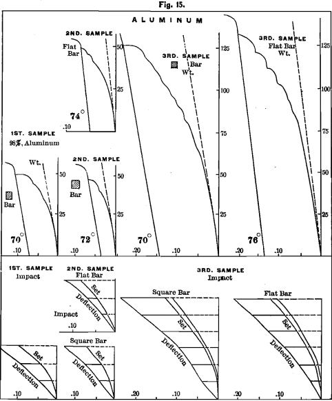
In Fig. 15 we show, on the left hand, diagrams of both weight and impact. It shows proportionality for about 12 pounds. Its ultimate strength is 50 pounds. Total deflection, 0.08; elasticity, 0.035 ; set, 0.045 ; rigidity, 70°.
The shrinkage was 0.185 for the square bar, and 0.170 for the thin bar cast with it. This shows that aluminum will not take any chill in being cast in a mould. The relative hardness of this sample is 10. This is the hardness of commercially pure platinum, and as this sample is as pure as the metal will generally be found, we may adopt 10 as the hardness of aluminum. It is also the hardness of the brass tested in Fig. 14. In filing this sample, the teeth of the file filled a little less than with brass.
Second Sample.—Al, 95.50; Si, 1.62; Fe, 2.88 per cent. This is also from the Pittsburgh Company. Shrinkage, 0.191 for the square and 0.188 for the thin bar. The upper diagram is made from a flat bar cast with the above, ¼ X 1 X 6 inches in size. The records for the square bar, as shown by the diagrams below this, are: ultimate strength, 50 pounds; proportional for about 12 pounds ; deflection, 0.065; elasticity, 0.03; set, 0.035; rigidity, 72° ; hardness, 12.
It will be noticed that with aluminum all spring lines are straight. Mr. Tucker found the sp. gr. to be 2.72. His results for tensile strength were:

The Pittsburgh Testing Laboratory found the following results for compression of samples sent them :

Third Sample.—Al, 93.50; Si 3.80; Fe, 2.50 per cent. This is also from Pittsburgh.
The shrinkage is 0.182 for the square and 0.168 for the thin bar. We give at the extreme right of Fig. 15 diagrams of both weight and impact from a flat bar ¼ X 1 X 6 inches in size. At the central part of the figure we show diagrams from square bars. The ultimate strength is 125 pounds and proportionality continues to about 25 pounds. Deflection is 0.19; elasticity, 0.08; set, 0.11; rigidity, 70° ; Hardness, 12.
Fourth Sample.—This aluminum was made under the Gratzel patents by the Aluminium Magnesium Fabrik Co., Bremen, and was furnished to us by Charles T. White & Son, 134 Pearl street, New York.
The Pittsburgh Testing Laboratory found this to contain Al, 93.20 Si, 5.95; Fe, 0.85.
The manufacturers claim that the metal probably contained Al, 96.96 ; Si, 0.59; Fe, 1.790.
We present a diagram of a square bar of this metal in Fig. 16, showing ultimate strength, about 100 pounds; proportionality continuing past 30 pounds; deflection, 0.16; elasticity, 0.07; set, 0.09; rigidity, 68°. The shrinkage of the square bar was 0.166.
Mr. Theodore Stevens tested samples of this metal for us with the following results:

Fifth Sample.—Al, 96.36; Si, 2.16 ; Fe, 1.47, Cu, 0.02.—This was a small cast sample ¼ X 1 X 6 inches in size, made by the Pittsburgh Reduction Co. and sent in a letter. It shows remarkable physical properties; we show a weight-diagram from this flat-bar in Fig. 16, and below it an impact-diagram. (To allow comparisons to be made we have recorded in Fig. 15 diagrams from the same sized flat-bars of samples 2 and 3.)
In this bar ultimate strength is about 120 pounds; proportionality extends to about 70 pounds; deflection is 0.08; elasticity is 0.05 ; set 0.03; rigidity, 78°; hardness, 10.
The impact-diagram brings out the good qualtities of this metal. It bears impact much better than the bronze in Fig. 14. It requires but little if any improvement to make it equal in every way to that metal. We sent a bar to Mr. Tucker, who reported that the bar broke through a large slag hole, but not until it had withstood 13,849 pounds per square inch tensile stress. The elongation in one inch for this stress was 5 per cent. Specific gravity was 2.67.
Increase of Strength and Rigidity of Aluminum
Some method is needed for increasing these properties in this metal. When the metal is supplied in the shape of rolled bars, wire, sheets or tubes, aluminum is much stronger than when cast.
To exhibit the effect of rolling, we add in Fig. 16 diagrams from a rolled bar of Gratzel’s aluminum of the same quality as the fourth sample. The bar was ¼ X 1 X 6 inches in size; ultimate strength is about 200 pounds; proportionality continuing to 120 pounds; deflection, 0.14; elasticity, 0.09 ; set, 0.05; rigidity, 78°.
We endeavored to cast a flat-bar in the same shape from this rolled piece, but by mistake the metal was spilled in the furnace and was recovered in the ash-pit. From its color it has evidently taken up some iron. The cast-bar is therefore not exactly an example of what a cast-bar of the same dimensions would show, though it makes a record that must be near the truth. A comparison of this bar with the rolled bar shows the amount of strength that the metal gained from rolling. The strength of the cast-bar is about 100 pounds ; proportionality about 30; deflection, 11; elasticity, 0.055 ; set, 0.055; rigidity, 74°.
The strength which Barlow gives for aluminum is 26,800 pounds per square inch (tensile). He says he tested a bar cut from a rod (probably rolled) ¼ inch square and 3 feet long. This metal would probably be stronger than the Gratzel metal, that we have tested, for it was rolled on four sides, while the bar which we tested was cut from
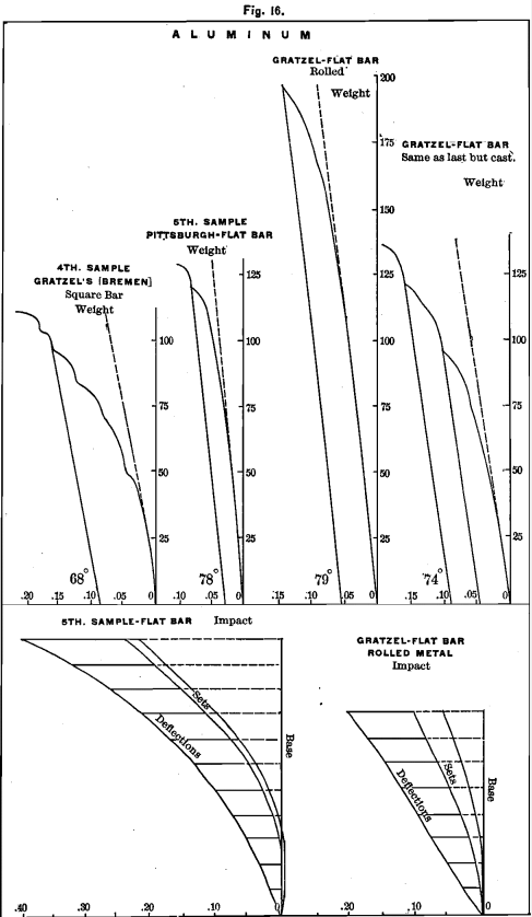
a sheet ¼ inch thick. If we compare the tensile strength, 18,866 of the cast bar of this last metal (fourth sample) with Barlow’s strength, we find on comparing the diagrams of cast and rolled in Fig. 16 that the transverse strength varies in about the same ratio.
ALUMINUM ALLOYS
We have made a few experiments to ascertain the effect produced by additions of copper and of tin to aluminum, the results of which are presented below.
Aluminum and Tin
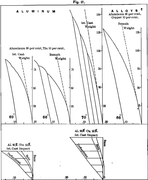
Al (sample 3), 90 parts, and tin (Fig. 9) 10 parts by weight. We show diagrams from this alloy in Fig. 17.
Shrinkage, 0.157 for the square, and 0.152 for the thin bar (a great reduction for so small a percentage of tin); ultimate strength, about 85 pounds; proportionality, 25; deflection, 0.15 ; elasticity, 0.06 ; set, 0.09 ; rigidity, 69° ; hardness, 8.
The alloy was remelted to see if this would improve its qualities. Its shrinkage was 0.148 for the square, and 0.142 for the thin bar; strength about 80 pounds; proportionality, 25; deflection, 0.17; elasticity, 0.06; set, 0.11; rigidity, 66°; hardness, 14.
The spring-line of aluminum seems to be straight, but the 10 per cent, of tin changes it to a curve. It is straighter in the remelt.
Aluminum and Copper
We took 90 parts by weight of aluminum (Sample 3) and added 10 per cent, of the purest copper wire. The result was in every way beneficial, but not to any great extent. The shrinkage for the square bar was 0.141, which shoves a remarkable decrease when we consider the very high shrinkage of copper, and also of aluminum. The diagram in Fig. 17 shows ultimate strength to be about 150 pounds; proportionality continuing to more than 50 pounds; deflection, 0.17; elasticity, 0.09; set, 0.08; rigidity, 70°; hardness, 10. The spring-line is straight. The alloy resists impact better than without the copper addition.
Aware of the impression that bronzes improve by being remelted, we cast this over again; but we found it to deteriorate in every way. Its shrinkage was now 0.137 for the square and 0.098 for the thin bar; strength, 125 pounds; proportionality, 30; deflection, 0.20; elasticity, 0.10; set, 0.10; rigidity, 66°; hardness, 18. The metal at the part of the bar lowest in the mould is white and crystalline, like aluminum, while the upper part of the casting is darker when viewed with the naked eye. This color is partially due to the metal being a mass of minute blow-holes. The inner surfaces of many of these holes are more or less iridescent, and between the honey-combed upper part and the solid lower part is a layer of blow-holes much larger than those above it.
From this result it seems that a small amount of copper does not alloy well with a large percentage of aluminum, yet this behavior may be due to some other peculiarity in the alloy that we have not noticed.
Aluminum Bronze
This is composed of about 90 per cent, copper and 9 per cent, aluminum. This mixture behaves in a very different manner from the alloy last considered, in which the percentages are reversed.
The two samples of which we show diagrams were made in the
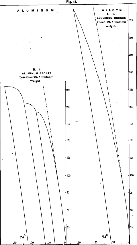
Cowles electric furnace. The B 1 metal contains less than 9 per cent. Al, and the A 1 metal is said to contain about 9 per cent., and between one and two per cent, of silicon.
The B 1 bronze has a shrinkage of 0.258 for the square, and 0.243 for the thin bar; strength, about 190 pounds; proportionality, 80; deflection, 0.15; elasticity, 0.105; set, 0.045; rigidity, 74°; hardness, 20.
The A 1 bronze has a shrinkage of 0.246 for the square, and 0.242 for the thin bar; strength, about 400 pounds; proportionality continuing above 90 pounds; deflection at 325 pounds is 0.29; elasticity, 0.20; set, 0.09; rigidity, 7 4°; hardness, 20.
At 400 the curve of the diagram had not materially changed. The deflection was 0.39; elasticity, 0.145; set, 0.145. The springline of aluminum bronze is a curve.
The impact-diagrams bring out the peculiarities of the metal.
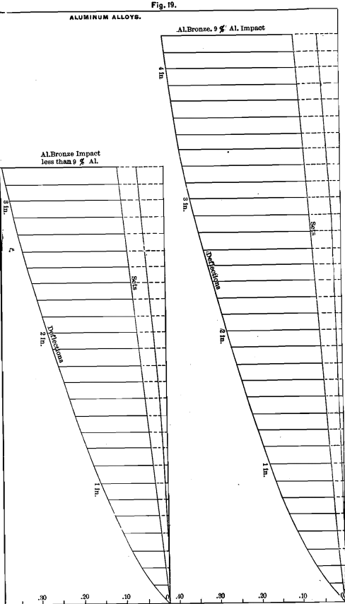
These diagrams were taken from the same bars that were first tested by weight, and are not, therefore, as interesting as they would be, if we had used a different bar. One reason why we have not referred to the impact-diagrams of this paper more often, is that often the same bar has been used for both tests.
The Effect of Silicon and Iron on Aluminum
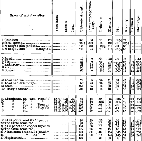
To allow of a comparison of the samples of aluminum which we have tested, we have brought the results together in tabular form.
The elements which should be especially considered, are strength, proportionality, elasticity and rigidity. The higher these are, the more favorable. The silicon increases quite regularly from the first to the last, and, as a general thing, all of the above-named physical results show a favorable influence for silicon. It would seem from the above, and from other results, that silicon is the natural alloy for aluminum.
If this shall prove to be the case, it will be a most fortunate thing, for silicon occurs in all aluminous ores, and it is difficult to prevent its presence in the metal. Again, silicon is lighter than aluminum, its specific gravity being only 2.34. It is said that the presence of silicon causes aluminum to oxidize, but among the above-mentioned samples we have not found any more tendency for one to oxidize than another.
It is still desirable that some material shall be found that shall harden aluminum and add even more strength than is given to it by silicon.
If iron, in very small quantities, has any effect upon the metal, it hardens it. It increases the size of the crystals, and when present in quantity as great as 5 per cent., the crystals have flat bright facets about 1/8 inch across, and the metal has become of no value.
Great Strength for Aluminum
The question may be asked : Why do we so often read of the great strength of aluminum?
In his book on Aluminum, Richards quotes (p. 63) from a paper read by W. H. Barlow, before the British A. A. S., in 1882, that the tenacity of steel is 78,000 and of aluminum 26,800 pounds per square inch, and says:
“ It thus appears that, taking the strength of aluminum in relation to its weight, it possesses a mechanical value about equal to that of steel of thirty-five tons per square inch tensile strength.”
This may have been where the idea of great strength originated.
The great advantage that aluminum is to have over other metals is its lightness; therefore, we should compare equal bulks and not equal weights. The misunderstanding here arises from the scientific meaning of “ mechanical value” not being commonly understood.
To show the danger of misapprehension from such a method of computation, examine the diagrams from the bar of maple wood and from the bar of tempered steel, and reason in the same manner. Mr. Tucker found for us that the tensile strength of this stick of maple wood was 16,464 pounds per square inch (with no elongation).
One cubic foot of maple weighs 47 pounds. One cubic foot of steel weighs 490 pounds, with a tensile strength of 78,000 pounds per square inch. Put this into the form above quoted and we have:
In relation to weights, the mechanical value of maple wood is more than twice that of steel.
One of the reasons that steel is used for beams is its great strength when compared with wooden beams of equal size. When we begin to compare maple beams of equal weight with an iron beam it must be ten times as large. Other questions present themselves when we talk of using such ponderous wooden beams which do not admit of a fair comparison being made.
Aluminum is desirable on account of its lightness, and we hope an alloy may be made which shall give the requisite properties for forming castings which shall be suitable for all uses to which brass and bronze castings are now applied.
