Table of Contents
Of the treatment of the slime-pulp of gold- and silver-ores by cyanidation, agitation is an essential part. When prepared for treatment, this pulp, consisting of ore reduced to such fineness that approximately 80 per cent, of it will pass through a 200-mesh screen, is mixed with a certain proportion of water, carrying in solution the quantity of cyanide (KCN) and other chemicals required.
The water-constituent of the pulp thus prepared usually ranges from 1 to 2 parts by weight to 1 of the dry ore. Thus constituted, the pulp is charged into treatment-tanks, the shape and capacity of which vary, according to the quantity of pulp to be treated daily and the method of agitation to be employed. Tanks have no other function in a cyanide plant than that of being economical and convenient containers or receptacles for holding the pulp, solution, or water used in the operations.
It is by agitation that the solids in the pulp charged into the tanks are kept in suspension in, and mixed with, the solution in the proper proportions required for the treatment. If the proper mixture of solution to solids be determined to be 2 to 1 by weight (which is, approximately, 5 to 1 by volume), this proportion should be maintained in every part of the charge; that is, each solid particle of the pulp, whether it be of 180- or 400-mesh size, should be surrounded by five times its own volume of solution throughout the whole period of treatment. The reason is, that the amount of chemicals ascertained to be necessary for dissolving the gold and silver contained in the solids, is held in uniform solution in the water-constituent of the pulp, and, therefore, the determined proportions of solution and solids must be maintained at all times during treatment. If the pulp should be allowed to thicken at the bottom of the tank so that it would contain, by volume, say, only 4 parts of the solution to 1 part of solids, it is plain that there would be present in this part of the tank-charge only four-fifths of the chemicals necessary for the treatment of the solids, while the one-fifth lacking would be present in another part of the tank-charge where it was not required. This principle, the importance of which is not always appreciated in the operation of a cyanide-plant, is the main ground for the necessity of agitation. But, besides maintaining the proper proportional mixture of solution and solids in the tank-charge, agitation is designed to give the required “ aeration ” to the pulp during treatment.
Means of Effecting Agitation
In the cyanide-plants built before 1907, agitation was effected in tanks 10 to 12 ft. deep, and ranging in diameter up to 30 ft., by mechanically revolving stirring-arms, assisted by centrifugal pumps drawing the settled pulp from the bottom of the tank and throwing it back on the top of the charge in the same tank. This method was fairly efficient, but expensive in both the construction and the operation of the plant; and it was superseded by pneumatic or air-lift agitation, which proved to be at least equally efficient, and much more economical.
The method of air-lift agitation which came into general use in cyanide-plants is known as the Pachuca-tank system. The superior economy of air-lift agitation and the energy of the patentees of this system soon brought this method into popularity, and most of the recently constructed cyanide-plants have adopted it.
Analysis of the Pachuca Tank and Its Operations
Fig. 1 is a sketch of the Pachuca tank and its pipe-equipment. Beside it is shown a Parral tank of equal holding-capacity, Fig. 2. The Pachuca tank is a tall cylinder with a conical bottom. In the center of the tank is fixed the air-lift tube, which, commencing about 18 in. from the apex of the bottom, extends to within a few inches of the top of the tank. The diameter of this tube is proportioned to the diameter of the tank as 1 to 12 approximately.
In Fig. 1, AA are the sides of the tank; BB is the air-lift tube; CC, the pipe which delivers the compressed air into the bottom of the air-lift tube; D, the foot-rest which holds the compressed-air pipe in the center of the air-lift tube; EE, an auxiliary compressed-air pipe used for delivering compressed air at the bottom of the tank, to keep the pulp in agitation while the charge is being received; FF, a system of pipes extending radially from a hollow “ bustle ” or distributor attached
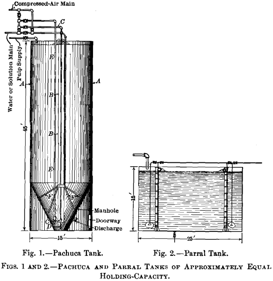
to the air-lift tube, to which is connected a feed-pipe leading from the air-main at the top of the tank, through which feed-pipe compressed air or solution under pressure may be turned into the bottom of the tank, to assist in agitating the pulp while the tank is being charged, or, in case of packing, to restore the pulp to a fluid consistency so it can be moved through the air-lift tube.
The compressed-air, high-pressure solution, and pulp-charging mains for the pipe-connections are shown at the top of the tank. It should be noted that the end of the compressed-air pipe, CC, is capped, and, for a length of about 7 in. next to the cap, is perforated by a number of small holes through which the compressed air escapes into the air-lift tube. To prevent the pulp from entering these holes and choking the pipe, when the compressed air is shut off, a tight-fitting rubber stocking or tube is drawn over the holes and clamped to the pipe above them. When the air is on, this stocking expands and the air flows underneath it and escapes at its lower end, which is left open. When the air is shut off, the stocking closes over the perforations and prevents the pulp from entering them.
In operation, when the tank is receiving its charge from the pulp-charging main, compressed air is turned on through pipe EE to keep the pulp in agitation and prevent it from settling in and around the bottom of the air-lift tube.
In case the compressed air fails during the charging of the tank, and the pulp packs so hard around the bottom of the air-lift tube and the rubber stocking as to prevent the operation of the air-lift when the compressed air comes on, air, or solution, or both, may be turned into the auxiliary pipes EE and FF, to bring back the packed pulp to fluid consistency; and, in case this fails, the tank is provided with a man-hole, shown in the figure, which may be opened, and the packed pulp excavated.
When the tank has received its full charge of pulp, compressed air is turned on in pipe CC, which starts the operation of the air-lift tube, and the auxiliary air-agitation pipes are then closed off. By the operation of the air-lift tube, the thick pulp at the bottom of the tank is drawn into and carried up through it, and discharged at the top, where it falls back on the tank-charge and mingles with the thin pulp there.
The transfer of the pulp from the bottom to the top of the tank continues throughout the treatment-period, and preserves the proper proportional mixture of solution and solids. By these means and in this manner, the agitation of slime-pulp is affected by the Pachuca-tank system.
Defects of the System
That this system was a great improvement over any other previously employed, there is no question; but that it has a number of commercial defects, is also true.
All these defects result from the design of the tank, and the apparatus with which it is equipped, the tank-dimensions being at variance with all the principles governing the object (other than as stand-pipes) for which tanks are employed. The great height and small diameter make the holding-capacity comparatively small, and consequently its cost of construction per unit of holding-capacity, high. The height of the tank and the large diameter of the air-lift tube necessitate a correspondingly high pressure and a large volume of compressed air to effect the transfer of the pulp; and this adds to the cost of agitation.
The pulp transferred through the air-lift tube overflows on the top of the charge, close around the tube, in which relative position the solid particles settle vertically to the bottom, where the steeply-sloping sides of the cone bottom carry them to the intake of the lift-tube, which throws them back again on the top of the charge. Under normal conditions of operation, the air-lift tube turns over the entire charge in a Pachuca tank of standard size in about 15 min. The violence of this operation would not be necessary to keep the pulp in proper mixture; but on account of the tall, narrow tank and the conical bottom, it is necessary, in order to keep the air-lift tube and the air-nozzle from being choked.
The air-nozzle within the lift-tube is a crude mechanical device, expensive to operate and expensive to maintain.
Before the proofs for these assertions are submitted, the principles of air-lift pumping should be reviewed. Those who have never had occasion to investigate the phenomena of air-lift pumping will find the subject fully dealt with in the experiments and conclusions of Dr. Pohle, who obtained a patent from the United States for the use of compressed air in pumping.
From Dr. Pohle’s experiments and those made by myself, my understanding is that pumping by compressed air is effected in the manner described below, with due reference to the conditions of the air-lifting or transfer of pulp in a tank for the purpose of effecting agitation. At the starting of agitation, after the tank has received its charge, the pulp-level is the same within and without the air-lift tube, which extends, say, 3 or 4 in. above the pulp-level. If the pulp has the consistency of 2 to 1 of solution and solids, the pulp-pressure on the bottom of the tank will be 0.54 lb. for each foot in height of tank-charge. The air-pressure for the agitation of such a charge should be 10 per cent, greater, or, say, 0.60 lb. for each foot in height of the charge. When the compressed air at this pressure is turned on in the air-pipe terminating near the bottom of the lift-tube, it flows into the pulp there, which has a pressure of only 0.54 lb. per foot of height. The compressed air, on entering the pulp in the lift-pipe, assumes the form of bubbles; and these, rising through the pulp, immediately unite to make a large flattened bubble which, extending to the sides of the pipe, takes the form of a disk or piston, in which form it rises to the surface, pushing the pulp before it. Rivalry now begins between the pulp and compressed air for the privilege of filling the space vacated by the ascending air-disk. The pulp, endeavoring to restore the hydrostatic equilibrium between the contents of the air-lift tube and those of the tank outside, and aided by its greater volume (due to the disparity of size between the compressed-air and air-lift tubes), rushes past the air-nozzle, holding back for a moment the issue of air. But, immediately, the air, on account of its higher pressure, again succeeds in entering the lift-tube in sufficient quantity to form another air-disk, with the same result as before. Thus by frequent jets of compressed air, alternating with rushes of pulp into the bottom of the air-lift tube, the lifting-operation is effected. The modus operandi of the air-lift, as above briefly described, is disputed by some, who hold that the inflow of air is continuous, and that the lifting effect is produced by the formation of a large number of bubbles in the pulp in the lift-tube, which makes it lighter, and, consequently, subject to displacement by the heavier pulp in the tank outside, rushing in at the bottom of the tube, and causing the discharge of the lighter pulp at the top.
A little study will show that this apparently logical reasoning cannot account for the operation of the air-lift, for individual bubbles rising through the liquid in the air-lift tube could have no more effect in lessening the hydrostatic pressure at its intake than would so many corks rising through it. On the contrary, it will readily be seen that, were the corks to unite and form disks or pistons filling the pipe, these disks would, on rising through the lift-pipe, carry the intervening pulp upward with them.
It is not improbable, however, that in certain kinds of liquids having great viscosity, the inflow of compressed air would be imprisoned as numerous small individual bubbles, and would in this way form an emulsion of the liquid within the tube, which emulsion, being lighter than the pulp outside, would be lifted or shoved upward by the heavier pulp coming in to displace it. But this condition would not be probable in the case of an ore-slime.
The principal defect of the air-nozzle of the Pachuca tank is the amount of ineffective work that must be done by the compressed air in making its numerous jet-like escapes into the air-lift tube. The superficial area of the exterior of the rubber stocking, that must open and close for each jet of air escaping, is 36 sq. in. at least; and on each inch of this area there is a continuous pressure of 0.54 lb. per foot in height of the tank-charge. As filled in operating, there are 43 ft. of pulp in the tank, making an external pressure of 23.22 lb. per square inch, or a total of 836 lb. on the movable part of the stocking; and this weight must be lifted by each jet of air admitted to the air-lift tube. In view of the great frequency of the air-jets, the enormous amount of useless work which this form of valve necessitates will be apparent. Moreover, the numerous alternate openings and closings of the rubber stocking soon destroy its elasticity and wear it out. The difficulties attending agitation in Pachuca tanks are described by Huntington Adams, in a paper read at the Wilkes-barre meeting of the Institute, and need not be repeated here.
It should also be understood that the efficiency of air-pumping is affected by dimensions of apparatus, etc., differently from that of mechanical pumping. For instance, a mechanical pump designed for a 6-in. discharge-pipe will pump as easily the same quantity through a 16-in. discharge. But in the case of air-lift pumping, the volume and pressure of compressed air that would be sufficient to pump violently through a 6-in. discharge-pipe will have no lifting-effect whatever through a 16-in. pipe; for the compressed air would rise in a stream of separate bubbles through the liquid in the lift-pipe, and would not be of sufficient volume to form solid air-disks reaching from wall to wall of that pipe; hence the liquid column would be unbroken and would itself be in hydrostatic balance with that outside the lift-tube, and no displacement would result. This points to the economy of using the smallest air-lift tube consistent with the volume of liquid to be pumped.
The Parral-Tank System of Slime-Agitation
In this system, designed and developed by me, for which United States and Mexican patents have been obtained, the defects in the Pachuca-tank system above referred to have been eliminated, and corresponding advantages secured.
A complete tank-equipment of this system, consisting of five tanks, and capable of treating 500 tons daily, has been installed at the milling-plant of the Veta Colorado M. & S. Co., at Parral, Mexico. Besides the Parral tanks there are two-standard Pachuca tanks, one of which is used as a treatment-tank, and the other for holding the wash-water for the filter-press plant.
The Parral-tanks, 25 ft. in diameter and 42 ft. high, are equipped with the special piping and the apparatus peculiar to this system, while one Pachuca tank is equipped with the piping and apparatus of that system. The treatment-tanks (i. e., the one Pachuca and five Parral tanks) have been piped for the individual and continuous systems of treatment, and each of these systems has been tried out, separately, a complete record of the results being carefully kept. No advantage in the extraction of values has been shown by either of these systems over the other; but the continuous system is more economically operated by reason of its great simplicity and ” fool-proofness.”
Fig. 3 shows the battery of treatment-tanks. On the extreme right is the Pachuca tank, on top of which sits the deck-house

used for the titration of samples, while in the same row to the left are the five Parral tanks. Along the front of the tanks near their top are seen the piping for the continuous-treatment system, and the sampling-platform. In the center and lower left corner are shown the “excess” tanks and the battery of Kelly filter-presses appurtenant to the plant.
The object of the Parral-tank system of agitation is the same as that already described in reference to the Pachuca tank, but the tank-design and the mechanical equipment used are entirely different from those of the Pachuca system.
The Parral tank is flat-bottomed, 25 ft. in diameter and 42 ft. high, with a capacity three times as great as that of the standard Pachuca tank. For transferring pulp from the bottom to the top of the tank, four 12-in. transfer-pipes are set 12 in. from the bottom, 4 ft. from the tank-side and equi-distant from each other. The compressed air is admitted into these pipes through a patent nozzle fitted with a ball-valve, which automatically opens and closes, intermittently, as required in the jet-feeding of the compressed air. I refer to these as transfer-pipes, this being more accurately expressive than lift-pipes, for, practically speaking, the pulp is not lifted, but transferred from the bottom to the top of the charge.
In case the compressed air should fail, and in the momentary intervals between the jet-issues, the air-nozzle is securely and automatically sealed by the ball falling back on its seat, and the entrance of pulp to the air-pipes is prevented.
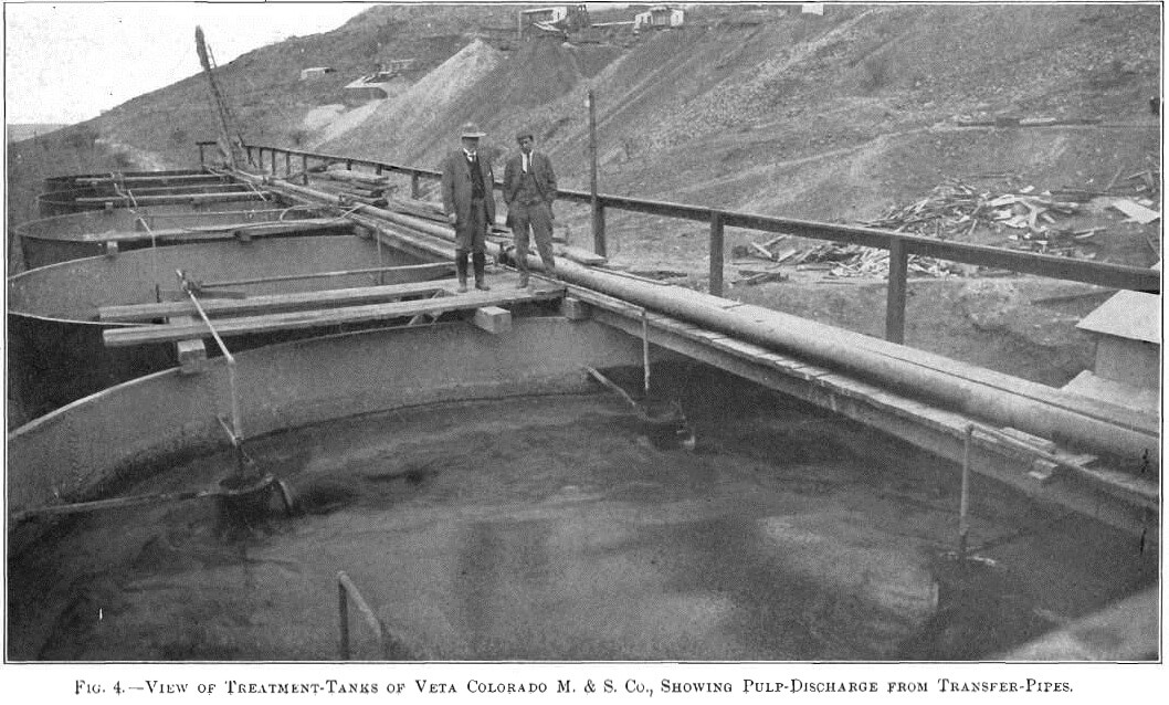
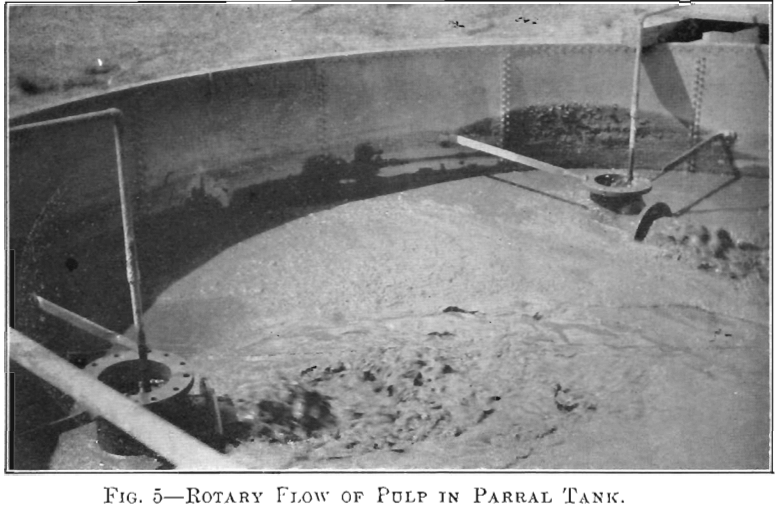
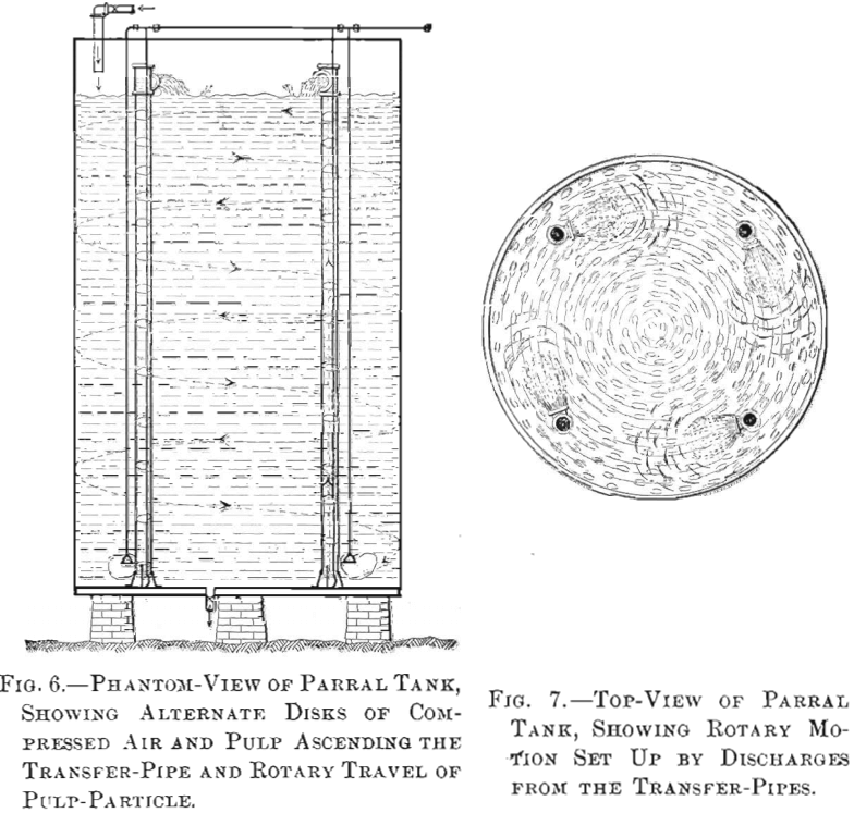
On the delivery- or top-ends of the transfer-pipes, tees of equal diameter are bolted, with the run in line with the pipes, and the outlets so directed as to discharge the pulp in line of segment-chords to the circumference of the tank. The discharge of all the transfer-pipes is in the same direction, and the force of the discharge sets up a spiral or rotary flow in the tank-charge which, in a short time, extends down to the bottom of the tank.
Figs. 4 to 7 show the pulp discharging from the transfer-pipes, and the undulations of the rotary flow set up in the tank-charge. The delivery-ends of three of the four transfer-pipes are shown in Fig. 4, but the rotary flow is perhaps more clearly seen in Fig. 5. When Parral tanks are receiving their charge for individual-charge treatment, an auxiliary air-pipe is extended down alongside each transfer-pipe to a point near the bottom of the tank, and the compressed air issuing from these pipes keeps the pulp in agitation and prevents its settling on the bottom. In the continuous system this pipe is never used.
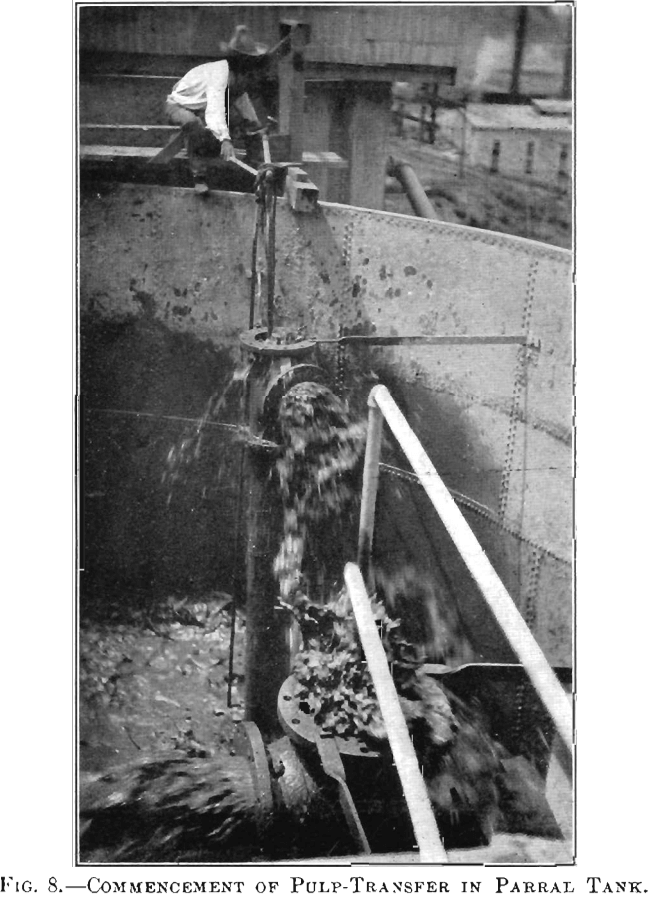
When the tank is filled to within 10 or 12 ft. of the top, the air is closed off the auxiliary pipes and turned on in the transfer-pipes. Fig. 8 shows a workman making this change and the transfer of the pulp (lift at this time) commencing. This figure shows also the method of making the transfer-pipes fast to the side of the tank, which is very secure and simple.
The spiral flow set up in the tank, as shown in Figs. 6 and 7, carries the pulp-particles round and round, so that the distance traveled by the pulp from the time it is delivered at the top until it reaches the bottom is many times greater than if it settled vertically, as in the Pachuca tank. In other words, the solids are carried in suspension by the rotary flow of the solution as they would be carried in a flowing river; the settlement of the heavier particles is thus retarded; and, consequently, the necessity for transferring the pulp from the bottom of the tank to the top is proportionately lessened, and the cost of the work is comparatively reduced.
In the Parral-tank system no special diameter of tank need be adhered to as in the Pachuca system. The relation of the diameter to the height of the tank may be whatever is economical in holding-capacity, which should be the main consideration in determining tank-diameters.
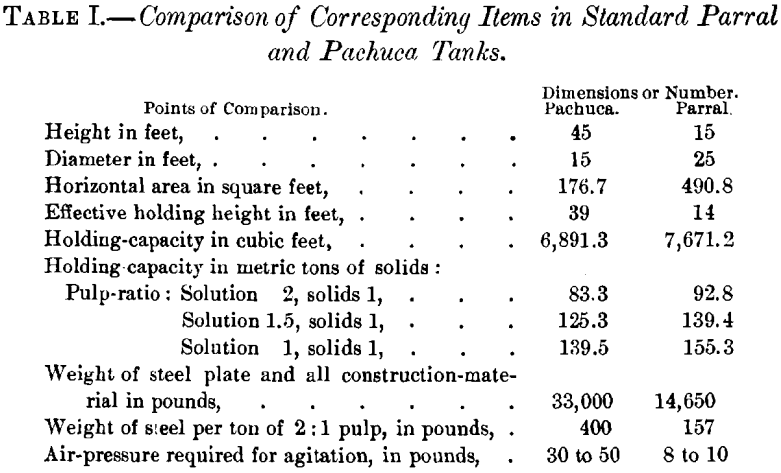
To secure, under this system, perfect agitation and the necessary rotary flow in tanks of the largest diameter, it would only be necessary to install a proper number of transfer-pipes, with discharge-outlets placed in the right direction to set up and maintain the rotary flow. A Parral tank (see Fig. 2), of the same holding-capacity as a standard Pachuca tank, would be 15 ft. in height by 25 ft. in diameter, and would be equipped with four 8-in. transfer-pipes; while the necessary pressure of compressed air would be only 8.5 lb. per square inch. The comparative cost of construction and operation of these two types of tanks is easily estimated.
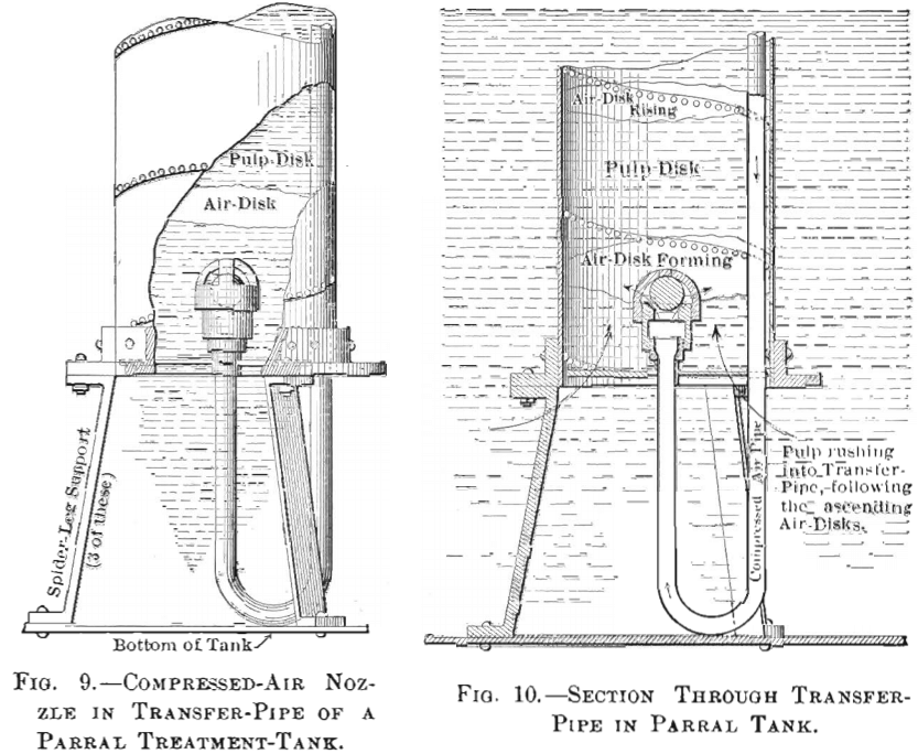
The compressed-air nozzle with its ball-valve, which was designed and patented for the Parral-tank system of agitation, may be used in any air-lift, and makes for the highest possible efficiency of compressed air used as a lifting agency. Figs. 9 and 10 illustrate the construction and operation of this valve. An examination of the ball-operation will show that the pressure on it, due to the hydrostatic head of the pulp-charge, is balanced, except for the area of the ball that rests on the seat. The seat-area of the valve, which is 2 in. in diameter, equal to a horizontal area of 3.1416 sq. in., would leave an unbalanced weight of 73 lb. on the ball, if it were to replace the rubber stocking in the Pachuca tank—or 763 lb. in favor of the ball-valve.
As the air-nozzle is called upon to open and close several times each second in permitting the jet-discharge of compressed air into the transfer-pipe, the aggregate of the useless work which the rubber stocking imposes on the compressed air, and the comparative advantage which the ball-valve possesses over it, will be easily estimated. My reason for saying that the probable frequency of the air-jet discharge will amount to several per second, is, that the sounds of the seatings of the ball-valves, as heard by one going underneath the tank, seem almost as frequent as the blows of an air-hammer.
So far, I am not able to fix any period as the useful life of the Parral valve; for these valves have been in operation since the starting up of the plant, Feb. 6, 1911, and, at a recent date, had shown no signs of wear.
For comparison between the two valves on this point, it may be noted that the Panilla mill contains 12 standard Pachuca tanks, 10 of which were equipped with the rubber-stocking valve of that system, and 2 with the nozzle and ball-valve of the Parral-tank system. These tanks began operation on the first of January of this year; and the rubber stockings soon wore out and were replaced by Parral valves, while the Parral valves originally installed showed, when recently examined, no signs of wear and are apparently as good as ever. In this plant and in that of the Veta Colorado M. & S. Co., the Parral valves never gave any trouble in starting up, even after the air had been closed off for three hours at a time; while, under the same conditions, the valves of the Pachuca tanks were only started after a great amount of trouble.
Although the transfer-pipes in the Parral tanks are 12 in. in diameter, I believe 6-in. pipes would produce sufficient rotary flow in the tank-charge to give the required agitation. In the operation of the tanks installed, when the transfer of the pulp is started and a strong rotary motion (about 10 ft. per second) communicated to the tank-charge, the air-valve is turned down until the flow of pulp from the transfer-pipes is reduced to one-third of their normal capacity, and so continued to the end of the treatment. By repeated tests, it has been shown that the extraction of values was as good with one-third the normal capacity of the transfer-pipes as when they were being operated at full capacity. From these tests it has been deduced that, so long as the spiral flow in the tank is maintained at a speed sufficient to retard materially the vertical settlement of the solids, so as to keep them suspended in proper proportion in the solution, the extraction of gold and silver proceeds just as rapidly as when the pulp is violently agitated.
I have no exact data from which to form an estimate of the comparative amount of air consumed per ton of pulp treated in the two systems, for the air has never been metered; but engineers who operated the valves on the air-pipes of both tanks, experimentally, with a view to estimating the flow of air by the proportional valve-openings, have reached the conclusion that it does not require more air to operate the four 12-in. transfer-pipes of the Parral tanks than the one 16-in. transfer-pipe of the Pachuca tank; and I venture my personal opinion that when a meter-test of the air-flow is made, this conclusion will be confirmed.
The comparative dimensions of the Parral tanks, as installed at the mill of the Veta Colorado M. & S. Co., and of the standard Pachuca tanks, with the individual equipment of each, are given in Table II. It may be repeated in this connection that 15 ft. is the largest diameter that can be given to the Pachuca tank, while the diameter of the Parral tank may be made as great and the height as low as desirable.
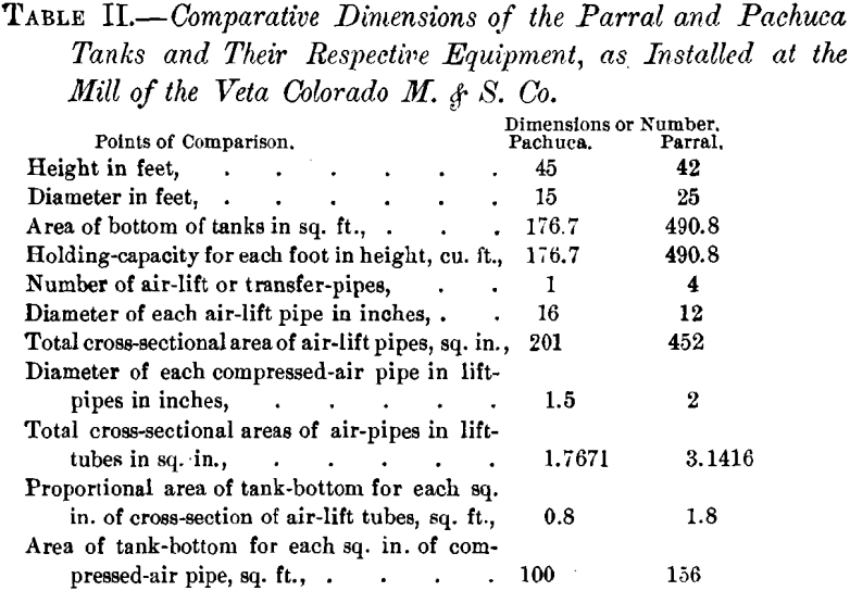
This table shows, especially if studied in connection with Table I., that, taking unit against unit in tank-construction and equipment, the Parral tank is the more economical.
Extraction of Values
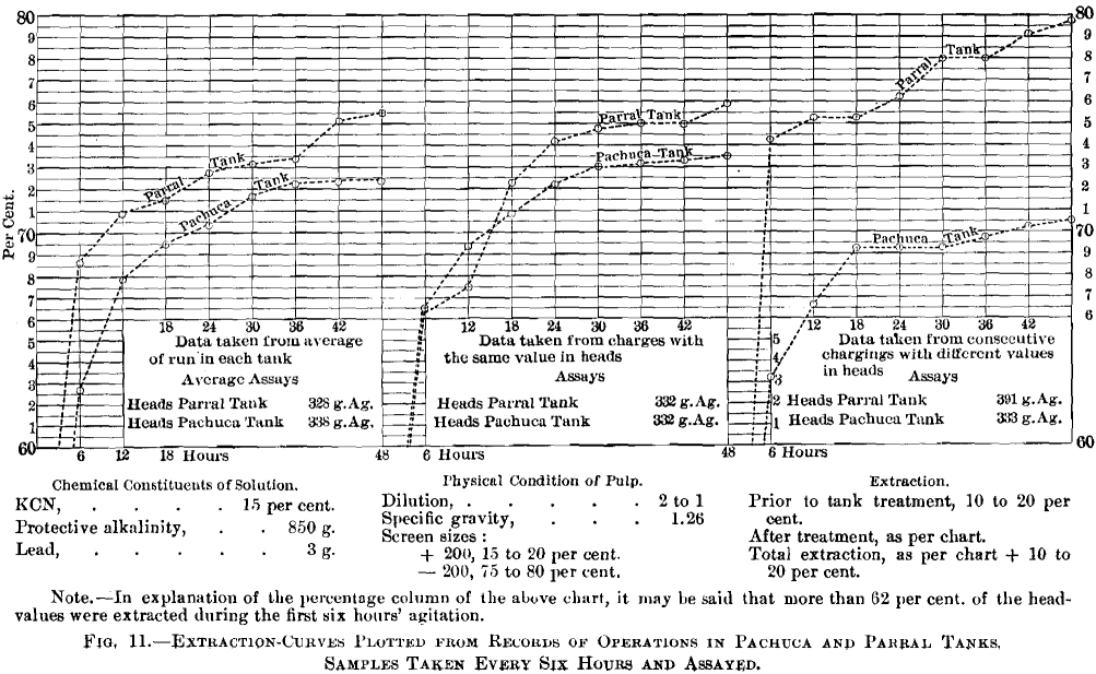
An unexpected result became manifest in plotting the lime-extraction curves, Fig. 11, from the assay-records of the samples taken, during the treatment-operations, from the Parral tanks and Pachuca tanks when operating on the individual-charge method. The curves show parallel results obtained from the two tanks treating similar pulp under three different conditions.
Conclusion
This paper is presented as the announcement of a new and improved system of slime-pulp agitation, for the consideration and criticism of metallurgical engineers connected with or interested in cyanidation. I have given much thought and study to the working out of the design and the development of its- mechanical details, and have had the pleasure of seeing my labors rewarded by complete success.
I wish to extend my thanks to William Thompson and Frank Reichmann, the superintendent and engineer of the milling-operations, respectively, who compiled the details of the operations and made the drawings submitted with this paper.

