Crushing Plant Design and Layout ConsiderationsCrushing Circuit “A’’ shows a small simple layout for use in mills up to 100 tons. In order to keep the flowsheet simple, and because of the use of the forced feed type of crusher, we can crush small tonnages up to 100 tons per day with a very simple arrangement; using a stationary or vibrating grizzly ahead of the crusher and then crushing the oversize before conveying into the fine ore bin. Elevators are often used for this purpose but are not recommended on very sticky ore.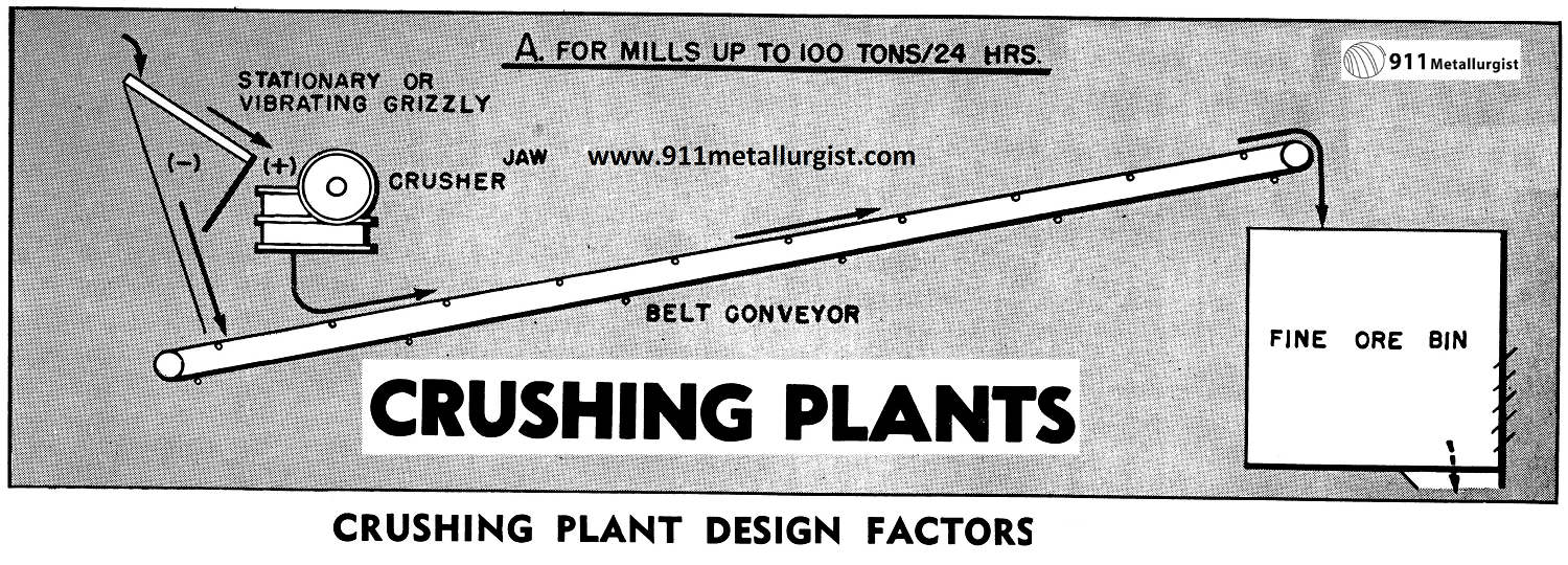
In Crushing Circuit “A” the chute leading from the stationary or vibrating grizzly should be steep, for wet, sticky ore will build up if there is not a nearly vertical drop on to the conveyor. If the bottom of the conveyor is in a pit, plenty of room should be allowed in back of the tail pulley for the mill operator to shovel if necessary. A drain should be provided in case of floods or spills in the mill. The conveyor should not be placed at an elevation of more than 20 degrees. The fine ore bin should preferably be a deep bin in which storage capacity for at least a 36 hour supply of ore should be provided. In other words, for a 100 ton mill, this fine ore bin should have a capacity of at least 150 tons.
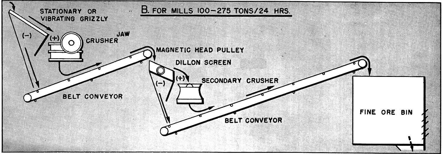
Crushing Circuit “B” shows the use of a secondary crusher for handling larger tonnages. The type of secondary crusher will vary according to the characteristics of the ore. Usually a cone type crusher is recommended for this secondary crushing, although in many cases a jaw crusher can be used as the secondary crusher, setting up the jaws closer than in the primary crushing operation. The interchangeability of parts is important if the two crushers are of the same size. The jaw crusher is the simplest and most fool-proof of secondary crushers. Rolls are often used where the shearing action of a roll crusher and a minimum amount of slimes are desired. However, rolls ordinarily should not be used to produce a feed finer than 1/8” and a reduction of 4 to 1 should be the maximum between the feed and discharge. Rolls have often been condemned because of the use of too small diameter rolls, cheap and poorly designed units.
For larger intermediate crushing the well-known cone gyratory crushers are recommended. Crushing Circuit “B” shows the use of a secondary cone crusher in the circuit between the primary crusher and the fine ore bin. A vibrating screen removes the undersize before the feed enters the secondary crusher. On small- tonnage plants, particularly on a steep millsite, this FLOWSHEET “B” is highly recommended, for both the primary crusher and the secondary crusher can be kept in a building in close proximity to each other.

Crushing Circuit ”C” shows the modification of Crushing Circuit “B” where a light-weight, secondary crusher can be placed over the fine ore bin. Often the fine ore bin is strong enough, together with additional steel supports, to make this simple arrangement practical.

Crushing Circuit “D” shows a very practical arrangement even for large-tonnage plants, enabling both the primary crusher and the secondary crusher to be in the same crushing building and to utilize the minimum amount of conveying. There is a great deal of merit to this crushing layout “D,” for the same conveyor belt can handle the products from two crushers and thus the minimum amount of conveyor equipment and building space is required. In most instances this crushing arrangement “D” will prove to be most practical from the first cost as well as from an operating point of view.
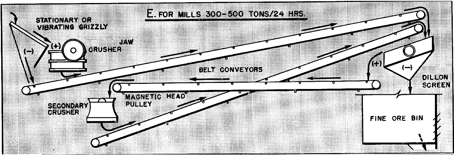
Crushing Circuit ‘E” was at one time the most common arrangement for a crushing plant in which large tonnages were handled. This arrangement was recommended where compactness and space were not as important factors as under the arrangement “D”. Crushing Circuit“E” covers the fundamental factors of a good crushing plant if floor space and expense are not critical.
Crushing Plant Design and Layout Considerations SUMMARY
In all of the above Crushing Circuit flowsheets we recommend a magnetic head pulley or a permanent magnet ahead of the secondary crusher to remove injurious magnetic material, particularly the detachable drill bits which are now becoming so common in many of our mining operations. One can readily see the importance of this magnetic protection, particularly since in many mines the throwing down of worn out drill bits is an every-day occurrence. The removal of the fines from the crushed material before each crushing stage is also a very important step in good crushing practice.
Aggregate Plant Flowsheet

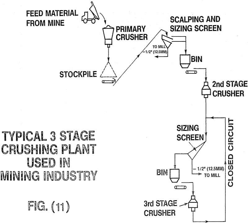
This flow diagram shows a three-stage gravel plant schematically. It shows the interrelationships and functions of the various components of the plant. This sort of diagram can be used to advantage in working out the solution of an aggregate plant problem.
Source: This article is a reproduction of an excerpt of “In the Public Domain” documents held in 911Metallurgy Corp’s private library.
Scientific Method to Design Crushing & Screening Plants
We should consider how the work is done by crushing machines, hammermills and pure impact crushers lift the kinetic energy of the material to a level where on sudden impingement against a stationary plate breakage occurs.
In a jaw or cone type crusher the geometry of the machine will have a bearing on the rate of energy application,
I am convinced that the plant designers and many equipment manufacturers have not paid sufficient attention to mechanical design criteria and how this affects machine productivity.
In a cone crusher the work done on the stone is performed by the mantle and concave, shown in fig, 1.
The amount of reduction that can be achieved is controlled by mechanical factors within the crushing chamber.
- Conical angle, shape and length of the chamber,
- Eccentricity and operating speed of the mantle,
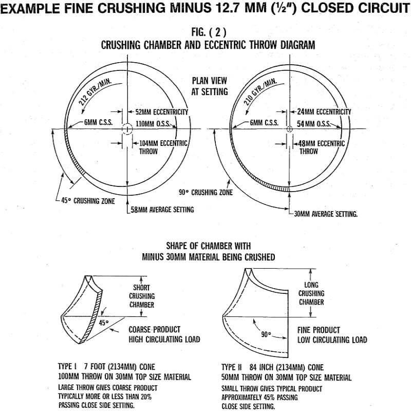
To demonstrate the effect of these, we should consider the following diagrams, firstly, fig, 2.
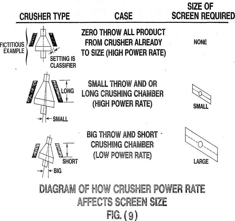
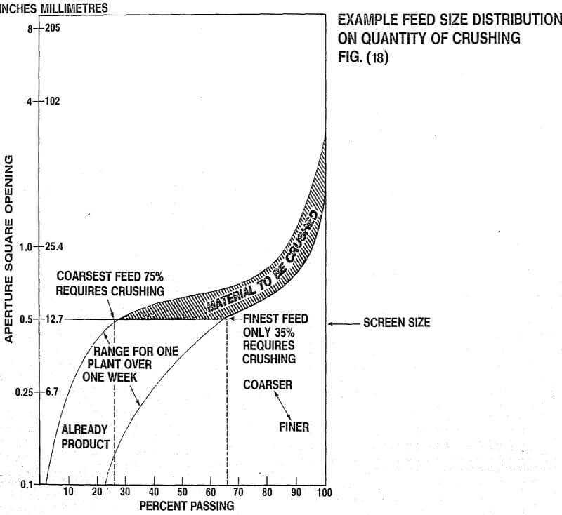
These two cone crushing configurations are commercially available and have entirely different concepts of the amount of ore being crushed as a proportion of the total feed, for the example shown (fig, 2), we are comparing two machines engaged in fine crushing with feed top size of 30 mm. This shows the smaller eccentric throw, longer chamber crusher can be expected to make a finer product at the same close side setting compared to the larger throw, short chamber machine, this is because it is working on a greater proportion of the feed, for further discussion, i will define this ability to inject energy per unit of feed as the power rate of the crusher.
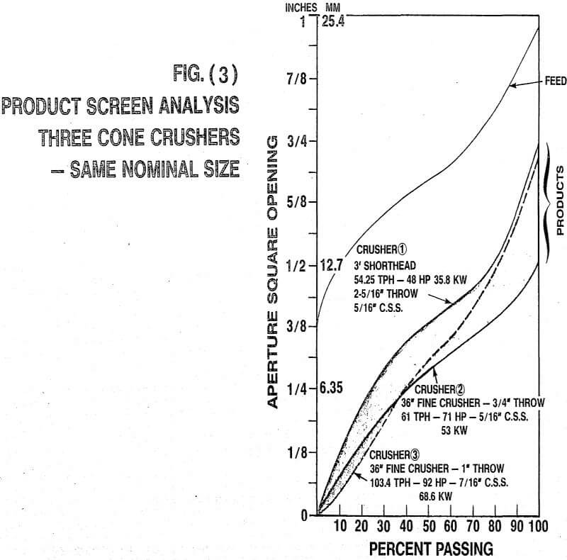
A number of field tests have been run verifying the effect of power. One is shown in Fig, 3.
This shows the product size distribution of three crushers, each with different eccentric throws being fed from the same BIN.
- Crusher (1) was set at 5/16″ (8 mm), had a short chamber and an eccentric throw of 2-5/16″ (59 mm), It choke fed at 54,25 tph and drew 48 hp (35,8 kw) on the crusher motor.
- Crusher (2) was set at 5/16″ (8 mm), had a long chamber and eccentric throw of 0.75″ (19 mm), It choke fed at 61 tph and drew 71 hp (53 kw),
- Crusher (3) was set at 7/16″ (11 mm), had a long chamber and eccentric throw of 1.0″ (25,4 mm), and choke fed at 103.5 tph and drew 92 hp (68.6 kw).
you will notice from these results that in each case crushers 2 and 3, with the smaller eccentric throws, made a higher percentage of finer products even though in the case of crusher 3 the close side setting was 40 percent more open.
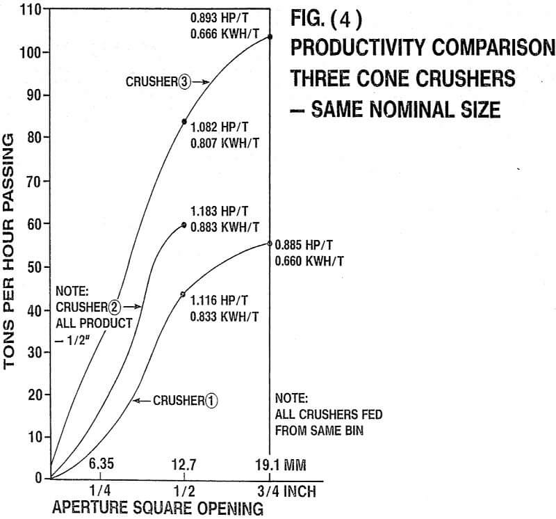
We should look at the quantities of sized product produced in these tests, as is shown in Fig. 4.
You can see that the crushers drawing more power produced larger amounts of any given top sized product.
Dividing the power consumed by the tons of size produced gave remarkably similar power per ton figures, results from other tests on other sized crushers processing many different materials seem to confirm that cone type crushers use the same energy to reduce similar quantities of material to the same size. The efficiency in the application of energy converted to useful work by the crusher, therefore, appears independent of eccentric throw.
If this were not a fact, it would invalidate Bond’s Third Theory for relating power and size reduction achieved in a compression type crusher.
From what we have just seen, there are two separate factors the designer needs to control in order to tailor the quantity and fineness of production in a.crushing and screening circuit,
- Power consumed by the crushers will directly affect productivity.
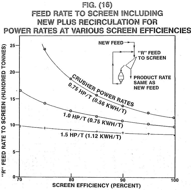
- The amount of energy applied per unit of feed the crusher power rate will affect product fineness.
The only variables in the process which we can control routinely are feed rate and setting change to the crusher. These affect the power consumed at the drive motor and rate of energy input as follows.
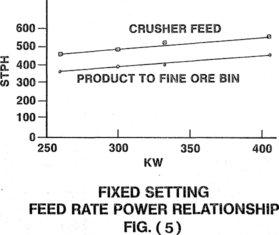
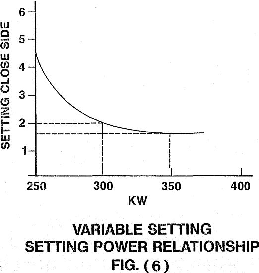
At fixed settings (fig 5) near the point of economic operating capacity, feed rate versus power drawn has a linear relationship. Power rate tends to remain a constant. With variable setting, power changes in an exponential relationship (fig 6).
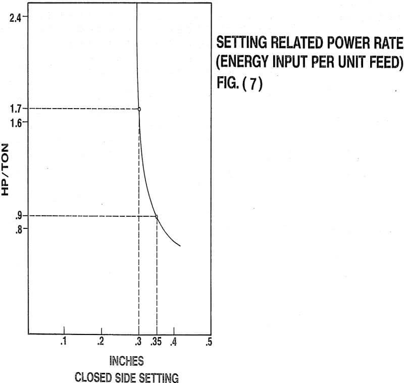
This example shows that for a very small change in setting there is a big change in power drawn, because for a small change in setting there is little volumetric change there will also be an exponential relationship in crusher setting versus energy per ton of feed (power rate) which is a direct measure of reduction, as is shown in fig, 7.
It should be obvious that if we can change the setting of the crusher whilst it is operating, we can affect both the productivity (consumed power) and, through the power rate the amount of reduction within the constraints set by the eccentric throw, speed and chamber configuration,
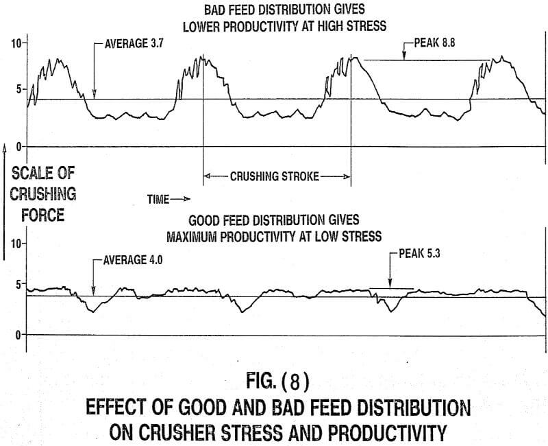
An important point which is often overlooked by plant design and application people is that the crusher must have an adequate amount of evenly distributed feed, fig, 8 shows the effect of poor and good feed distribution. If the feed is right the crusher will have maximum productivity (highest average crushing force) for minimum mechanical stress, a crusher cannot normally be fed properly from a vibrating screen discharge, this is why we have shown surge bins with pan or belt feeders in the diagrams that follow on plant discussions.
 |
 |
 |
 |
 |
 |
 |
 |
 |
 |
 |
 |
 |
 |
 |
 |
 |
 |
