Table of Contents
Most modern crushing and grinding facilities are automated to some degree. Some, of course, have a very minimum of automatic control whereas others utilize very complex control equipment. However, with very few exceptions, there has not been a new basic control philosophy applied in this field in the past seven years. The philosophy has been broadened in scope and applied to larger plants, some of them with data logging and so-called computer control, but almost always the same tried and proven basic control .philosophy is the basis for the control system.
Primary Crushing
At least one plant with a large gyratory crusher has been in service without an operator for over three years. Several others have recently been placed into service with no provision for a local operator; thus, control rooms located in the primary crushing plant will likely be omitted in any new plant designs.
In most coarse crushing plants the instrumentation is used primarily for monitoring the operation and for controlling feed or discharge equipment in such a manner that the crusher will not be damaged.
This level is often sensed by the use of gamma switches. These devices consist of a radio-active source and a detector. The source is usually sealed in a lead compartment in such a manner that it may be closed to prevent damaging radiation when personnel must work in the rock box. It has no moving parts and no connections to it and it may be compared to a small sun from which radiation is always being given off. In this case, however, this miniature sun is so surrounded by lead that its rays only go in the direction desired. The detector is a device whose action is similar to a simple photocell, but instead of being actuated by the presence or absence of light, it is actuated by the presence of radio-active energy. The absorption of radio-active energy as it passes from the source to the cell is almost directly proportional to the mass of the material between the two. The cell in this case is adjusted in such a manner that it will only trigger a relay when there is a quantity of ore between the cell and the source. Therefore, these devices lend themselves ideally to this rock level measuring operation since dust or-dirt, either on the equipment or in the air, does not give false signals of high level.
Fine Crushing
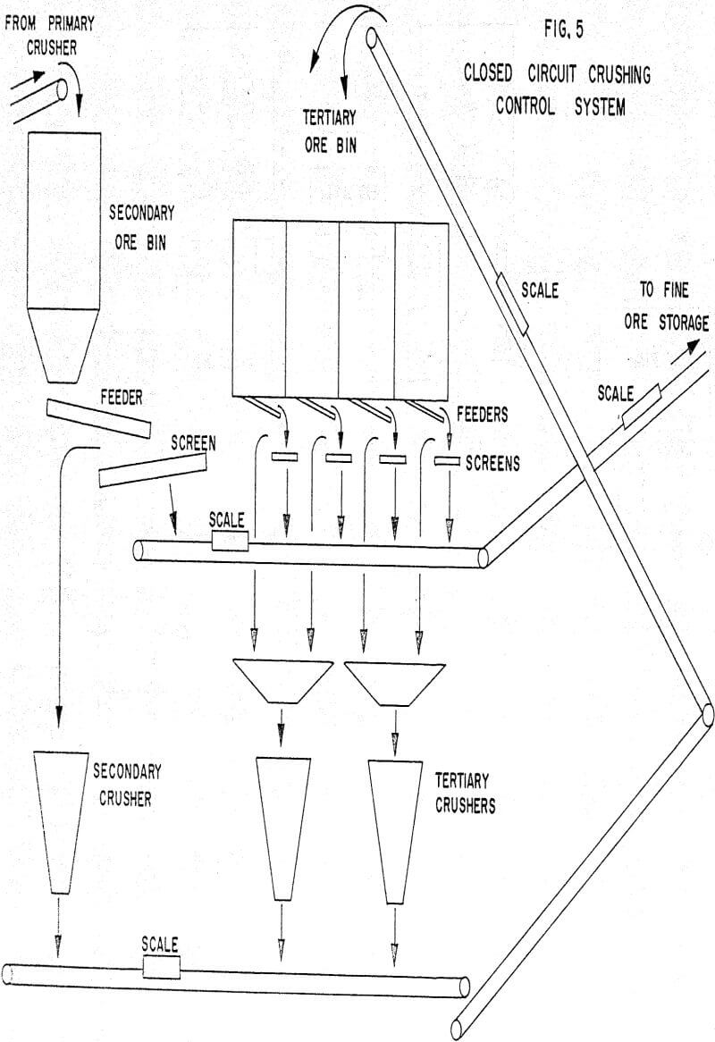
The automation of fine crushing plants has become very popular in the past four years, and although it is not new, it was not quick to be accepted. In practically every case which I have observed, the payoff for automation has been more rapid here than in any part of an ore processing operation. Increased production figures of twenty percent are common and in some cases plant operators report gains of up to forty percent. In many instances general operating costs per hour have dropped considerably, even at the increased production rate.
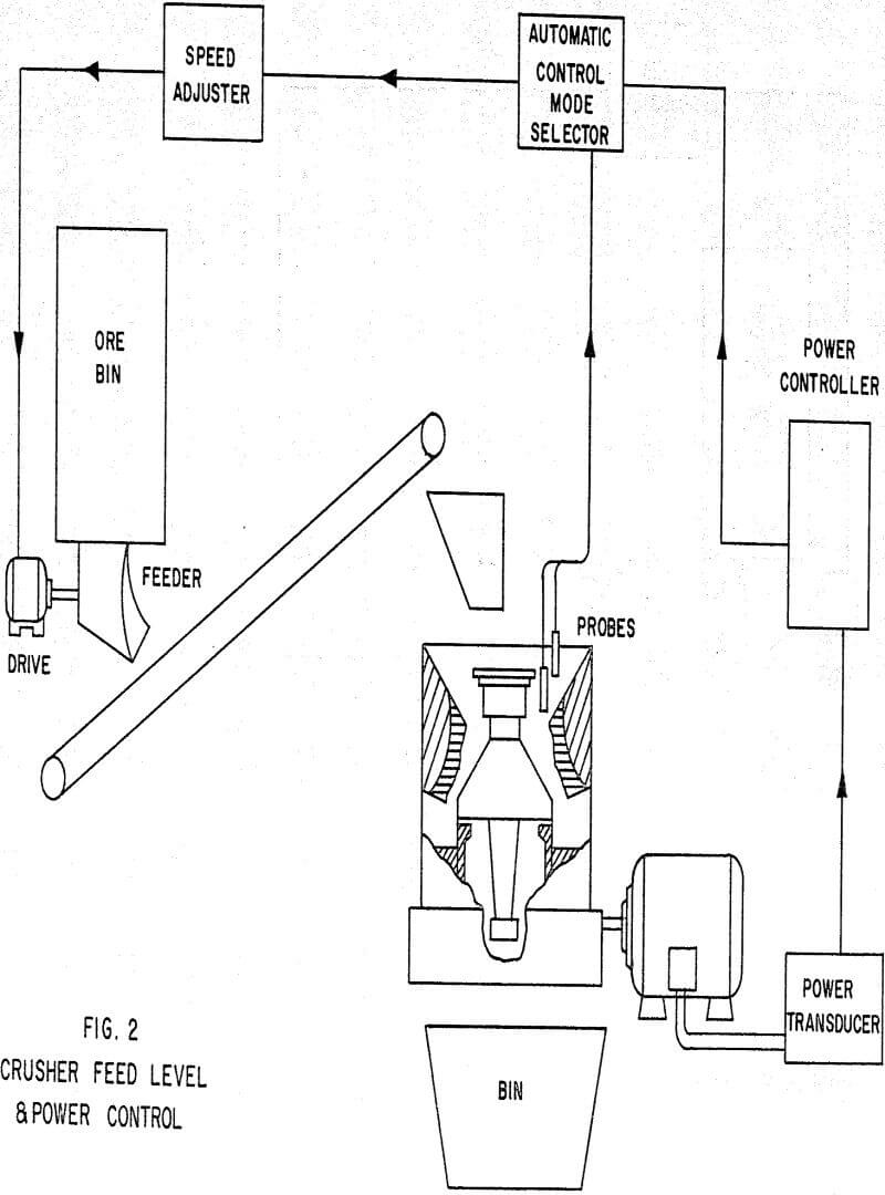
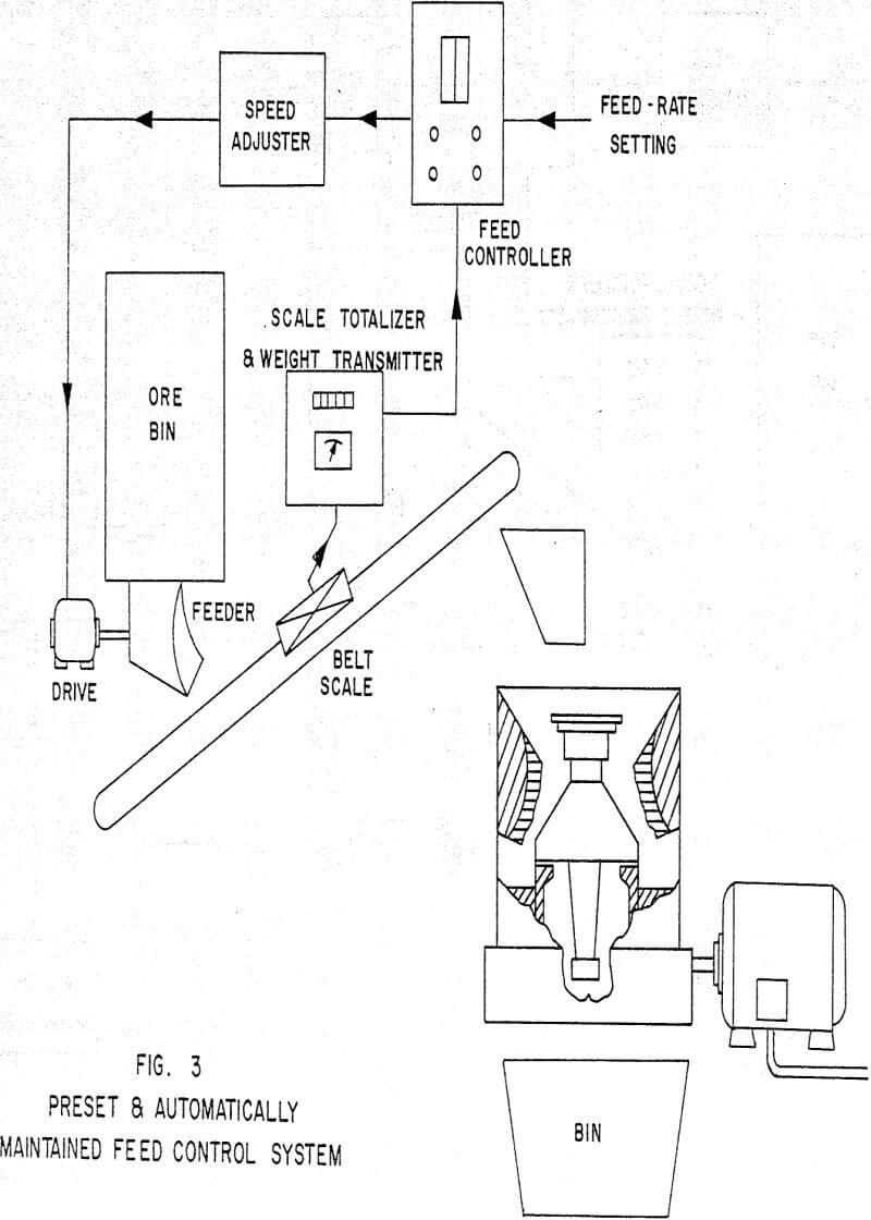
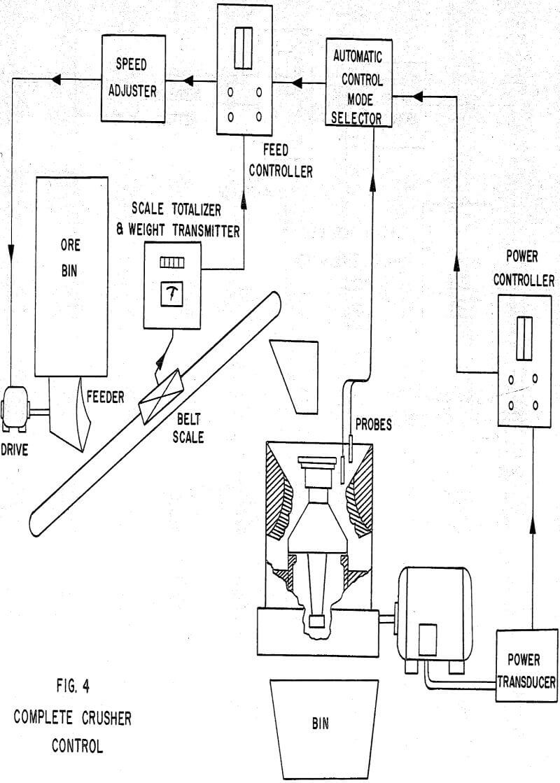
The basic philosophy behind the control is simply this: A fine crusher is not operating at its peak capacity if it is not either pulling maximum rated horsepower or if it is not at its volumetric capacity. Often the term “Choke Fed” is used to indicate volumetric capacity, and it will so be used in this paper. It is recognized that even for identical crushers this “Choke Fed” condition does not occur at the same volumetric capacity when crushing different types or sizes of ores.
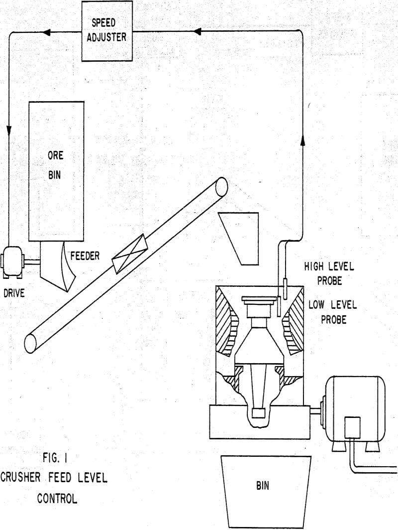
For the simplest case, I will quote almost verbatim from a case history at the New York Trap Rock Corporation. The crusher is a seven foot Symonds Shorthead fed by a pan feeder which is powered by a wound-rotor adjustable speed motor. Because feed size was large enough not to cause motor overload, the maximum throughput was assumed when the crusher bowl was maintained full. In this plant the operator controlled four such units and found it almost impossible to maintain full bowls without overflowing. Since overflows created clean-up work, the operator operated at a safe but not maximum feed rate.
One located as a high probe and the other as a low probe. When the level reached the high probe, the feeder speed through the feeder speed adjuster would be slightly reduced. When the bowl level dropped to the low probe, the feeder speed would be increased This type of modulating control usually requires a timed control override on the high probe. If the level did not drop below the high probe after a pre-set time, the feeder would stop until it did.
Grinding Control Systems
The feed rate to the cyclone is held constant by keeping a constant level in the sump ahead of the cyclone feed pump. The pump operating with a constant suction head thereby automatically controls the feed rate to the cyclones.
The density of the cyclone feed is held constant as follows: A density measuring unit is installed in the feed line to the cyclone. This unit senses any slight change in the density of the material and in conjunction with its converter, recorder and controller adjusts the feed to the rod mill to correct for the density change. If the feed is hard to grind, the density will tend to rise and the control system will reduce the feed to the rod mill. Conversely, if the density tends to fall, the control system will increase the feed to the rod mill to bring the density back to the desired setting.
This control system has what is known as a long dead time. After a change in the density is detected and a correction to the rod mill feed rate is made, the system must wait until the change in feed rate affects the density. This time is long because of the retention time of the rod and ball mills.
Water addition to the rod mill is controlled to maintain the correct percent solids in the mill by a control system which proportions the water addition in direct relationship with the feed of dry solids. Thus, when the density controller calls for more feed, the water addition is proportionally increased.
A brief description and the operation of the various control devices follows. The level in the cyclone sump is closely maintained by the level controller and water addition control valve. There are many ways to measure sump levels, but two methods which are commonly used operate as follows.
The density of the cyclone feed may be made with a gamma radiation gage. This gage utilizes a source of radiation supported on one side of the pipe carrying the slurry and a radiation detector on the other side. The source has a long life and changes in radiation intensity only slightly over long periods of time. The radiation detector measures the amount of radiation coming through the pipe and the slurry. Since the radiation absorption is proportional to the density of the material through which it passes, the output of the detector is proportional to the density of the slurry in the pipe.
When a wet autogenous mill is operated in closed circuit with cyclones, the control is similar in many respects to that used in the previously described system. The level control is on the mill discharge sump, the density gage on the feed line to the cyclones, the water addition is made at the mill feed end and the feed rate to the mill is adjusted identically.
With an autogenous mill the power drawn by the mill may become the limiting factor to further feed rate increases. In this case when the maximum desirable power is reached, the power control overrides the density control. The power control System is almost identical to that described in the crushing section of this paper.
This method of control, I believe, is a relatively new applied philosophy in control, at least when it is applied to very big mills.
In operation the desired weight of charge to be maintained in each end of the mill is set on a dial. When this weight is exceeded in either end, the feed is decreased in that end until the weight of the charge is again at the desired point. The same but opposite action takes place when the weight becomes less than desired.
The system is also provided with a mill power controller which will override the weight control and reduce feed if the power drawn gets greater than that set into the system as a maximum.
