Two methods of testing anchorages of headed expansion-type mine roof bolts were investigated by the Federal Bureau of Mines to determine whether they are acceptable for general use. In both methods a load was applied to a tightened bolt with a hydraulic jack. A total of 80 tests, 40 using each method, was conducted in 4 test areas in 3 commercial coal mines. Electric resistance strain gages were used in all tests to indicate true bolt load as the bolt was tightened and when an additional load was applied with the hydraulic jack.
The results indicate that:
- The relationship between the true bolt load and the jack load will vary according to the test method until the two loads become equal. The bolt load-jack load relationship below this point can be determined only with strain gages.
- The point at which the two loads become equal can be estimated by noting the load when the hardened washer becomes loose in one method, and when the bearing plate becomes loose from the roof in the other. It also can be approximated for either method of testing by noting the load when the first abrupt change in the slope of the jack load-bolt displacement curve occurs .
- The anchorage characteristics of the test bolt can be determined from the data obtained from either method by examining the slope of the jack load-bolt displacement curve above the point at which the true bolt load is equal to the jack load.
- The installed load on a bolt tested by either method may be approximated by projecting the slope of the jack load-bolt displacement curve back to the vertical or zero displacement axis and noting the load at which this projection intersects this axis.
This investigation shows that although both test methods are acceptable for determining the anchorage characteristics of any expansion-type bolt and shell assembly, one method is preferable over the other because it provides more data for making the determination.
The results presented in this report were made available to the Roof Action Committee of the American Mining Congress for use in establishing a standard roof bolt anchorage testing procedure.
Introduction
Anchorage testing of mine roof bolts is of major importance in estimating the relative safety and efficiency of proposed roof-bolt installations. The performance of the individual bolts in a specific area should be known before an attempt is made to design or set up a pattern of bolting the mine roof in that area. Each anchorage should be as strong as the yield strength of the bolt used. In practice this is not always attained because of the wide variation in the physical properties of mine roof rocks. In some instances, visual examinations of strata exposed in roof falls aid in locating strata horizons where the most efficient anchorages might be developed. Usually anchorage tests are necessary to provide specific information as to the type of anchor, hole diameter, and the strata horizon(s) which will provide the best anchorage.
A method of testing anchorages of ‘the headed expansion-type bolt and shell assemblies was presented in previous Bureau publications. Although the method described is still acceptable, more recent experience has indicated that certain improvements should be incorporated.
The publication covers a series of tests that were designed to compare and evaluate two anchorage testing methods currently employed in the industry.
The purpose of these tests was to find out whether the methods are acceptable for determining the anchorage characteristics of any expansion-type bolt and shell assembly.
The method of testing anchorages of headed, expansion-type bolt and shell assemblies suggested in previous publications has two disadvantages. It requires (a) the use of bolts approximately 6 inches longer than those that would normally be used to anchor at a particular horizon in the mine roof, and (b) immediate testing of the installed bolt. These requirements are necessary because the hydraulic jack used to load the bolt beyond the installed load is inserted between the bearing plate and the roof as an integral part of the roof-bolt assembly. These shortcomings indicated the need for an improved method that would permit testing of bolts of the same length as those normally used in a mine at any time after installation.
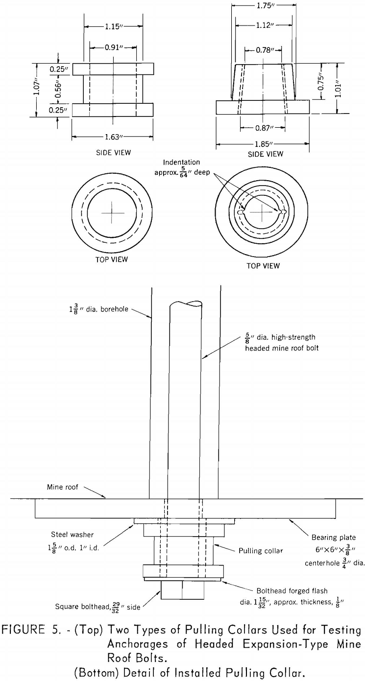
Before making any changes in the test apparatus and/or procedure, a survey was made of the testing methods used by manufacturers of roof-bolting materials. This survey revealed that the apparatus used and procedures followed were so similar they could be summarized in two methods of testing. In almost every case, the test bolt is installed in a normal manner with the exception that a specially designed steel pulling collar having a center hole is inserted between the head of the bolt and the bearing plate as part of the roof-bolt assembly. This arrangement permits the bolt to anchor within approximately 1 inch of the point at which the regular bolt assembly is anchored. It also permits attachment of the anchorage-testing apparatus at any time after the bolt has been tightened. The method of applying the additional load varies only in that in one method (method A) the pressure column or stand, which acts as a base for the hydraulic jack, presses directly against the bearing plate; and in the other (method B), the stand is fabricated in such a manner that the bearing plate is straddled. Bolt displacement is measured with either a dial gage or a graduated rod. The anchorage characteristics are usually determined from a graph made by plotting the jack load versus bolt displacement data.
The test apparatus used in these methods appear to eliminate the disadvantages stated previously. However, it was decided that the methods should be investigated further to determine the validity of the data obtained and the accuracy of the procedures used to evaluate the data before accepting either of them for general use.
The evaluation of the data to determine the anchorage characteristics has been inconsistent because no uniform procedure is followed to determine such important factors as the initial load on the installed bolt before applying an additional load with the hydraulic jack, and the point at which the load applied by the jack becomes equal to the load on the bolt. Both of these determinations are necessary if a valid interpretation is to be made of the data, and a fair comparison made of the results from different tests.
One procedure used to estimate both the installed load on the bolt and the point at which the bolt load and jack load are equal is to use the jack load value at which 1/32-inch bolt displacement occurs. Another procedure employed to estimate the installed load on the bolt is to project a straight line which approximates the slope of the jack load-bolt displacement curve back to the zero bolt displacement or vertical axis and use the load value at which the projection intersects this axis. In this method the bolt load and jack load are considered to be equal when the first abrupt change in the slope of the jack-load bolt displacement occurs. A third method (used to determine the equalization point of the two loads), consists of noting the jack load at which the hardened washer between the pulling collar and the bearing plate becomes loose when the pressure column presses against the bearing plate, and the load at which the bearing plate becomes loose when it is straddled. Because these procedures were empirical, it was deemed necessary to establish their validity.
Test Sites
Investigations were made in two selected areas in the Dehue Mine, in one area of the Renton Mine, and in one area of the Robena No. 2 Mine. The Dehue Mine is operated in the Eagle coalbed. The immediate roof of this mine at the first test site is dark gray, thinly bedded shale, with beds ranging from less than 1 inch to 6 inches in thickness. At the other Dehue test site, the immediate roof is sandstone, and the beds range from a fraction of an inch to 12 inches in thickness. Some of the beds are separated by thin bands of shale and/or coal. At both sites the roof is uniform in character throughout the length of the bolts. Anchorages were in shale at the first test site and in sandstone at the second.
The Renton Mine is operated in the thick Freeport coalbed. The immediate roof of this mine in the test area consists of bedded shales and sandy shales varying in color from light to dark gray and ranging in thickness from a fraction of an inch to several inches. Approximately 9 inches of top coal is left to protect the roof rock from weathering. Anchorages at this test site were all in shale.
The Robena No. 2 Mine is operated in the Pittsburgh coalbed. The immediate roof of this mine at the test site selected consists of several inches of top coal overlain by bedded sandstone varying in thickness. All anchorages at this test site were in sandstone.
Equipment and Procedure
The equipment used is pictured in figures 1 and 2 and detailed sketches are shown in figures 3 and 4. The testing equipment consists of five essential elements:
- A calibrated load-sensitive bolt equipped with a built-in electric-resistance strain gage to measure the true bolt load.
- A steel pulling collar to permit attachment of the bolt loading assembly to the bolt.
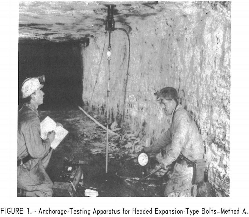
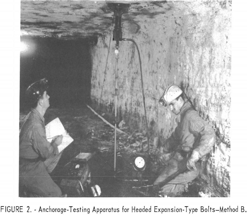
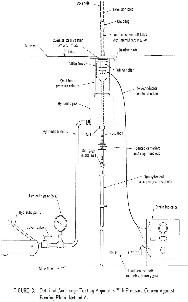
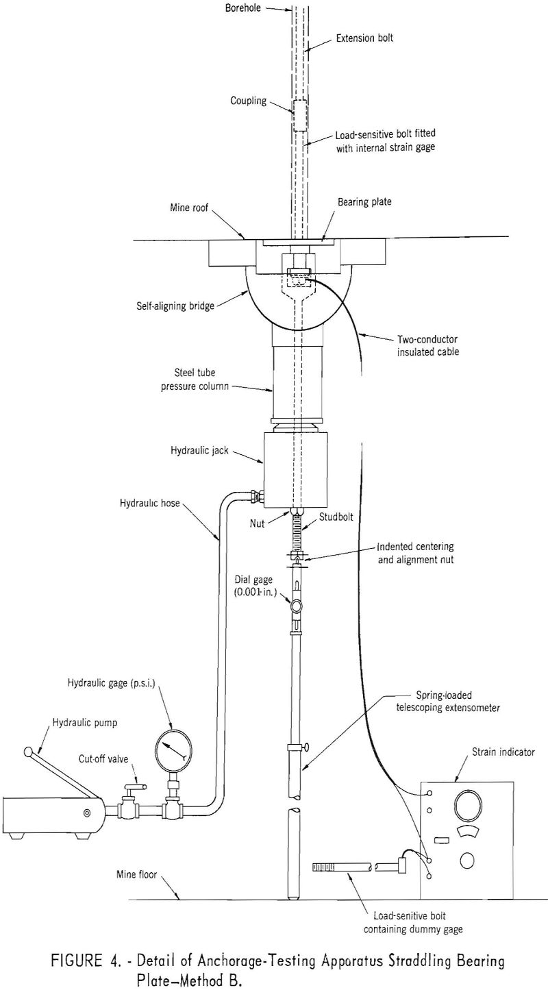
3. A puller head and threaded high-strength stud bolt for attachment to the collar on the bolt, which in turn accommodates the hydraulic jack, pressure column, and bridge.
4. A center-hole-type hydraulic jack to apply additional load to the bolt.
5. An extensometer to measure bolt displacement.
The headed load-sensitive bolts used are commercially available. They are fabricated from high-strength alloy steel ¾-inch diameter and 12 inches long. An electrical resistance strain gage of 120 ohms is mounted in a 1/16-inch-diameter center hole near the headed section of each bolt. Temperature compensation is provided by using a similar bolt as a compensating gage or “dummy.” The strain indicator used to measure strain is battery-operated. These special bolts were calibrated in a Tinius-Olsen testing machine to 20,000 pounds, before and after the tests, and were accurate to within plus or minus 1 percent at full load.
Figure 5 (top) illustrates two types of steel pulling collars generally used. The pulling collars and puller head are designed to withstand loads of at least 20,000 pounds. The bottom part of figure 5 shows an application of the pulling collar used in these tests.
The hydraulic jack is a twin-ram type of 17-½-tons capacity and is equipped with a 6-inch-diameter pressure gage having 100 pounds per square inch (p.s.i.) subdivisions over a range of 10,000 p.s.i. The gage was calibrated in a Tinius-Olsen testing machine before and after each series of tests underground. The accuracy was found to be plus or minus 250 pounds. The spring-loaded telescoping extensometer is used to measure the movement of the end of the stud bolt in relation to the mine floor. It is equipped with a dial gage that measures displacements of .001 inch over a range of 1 inch. Miscellaneous apparatus used in these tests consists of a 6-inch square steel bearing plate approximately 3/8-inch thick for use between the pulling collar and the roof, and an indented steel cap having an alignment washer to center the extensometer under the stud bolt. A commercial-type hole gage was used to measure drillhole diameter at the point of anchorage. The gage is calibrated in 1/16-inch increments; measurements to within 1/32-inch could be estimated.
The bolt assembly consisted of a load-sensitive bolt connected to either a 36- or a 60-inch long, 5/8-inch diameter, high strength mine roof-bolt extension by a reducing sleeve. The same make and type of conventional bail expansion shells were used to anchor the bolts in all tests.
The anchorage testing procedure was as follows: A vertical hole deep enough to accommodate the bolt was drilled in the mine roof with either a stoper or a rotary drill. A 1-3/8-inch diameter bit was used in each instance. The diameter of the hole at the anchorage point was measured with a hole gage. The assembled bolt fitted with a pulling collar was installed in the hole and tightened by a hand wrench until a load of approximately
6,000 pounds was indicated by the strain indicator connected to the load-sensitive bolt. Installation of bolts at substantially higher loads would have provided fewer values for determining the slope of the load-displacement curve before either the anchorage capacity or the yield point of the bolt was reached. All bolts were installed at approximately the same load to facilitate comparison of test results. The pulling apparatus was attached to the pulling collar on the bolt and a load applied until the gage on the jack showed 200 pounds. The extensometer was then set in position between the end of the stud bolt and the mine floor. Additional load was applied to the bolt in increments of approximately 1,000 pounds according to the hydraulic jack gage, until about 13,000 pounds was reached. This value was well below the yield point of the bolt as deter-mined by laboratory tests. Measurements were taken of the actual or true bolt load indicated by the load-sensitive bolt and the bolt displacement indicated by the extensometer at each increment of applied load.
The hardened washer (method A) or the bearing plate (method B) was tapped after each increment of load to determine the point at which it became loose.
Test Results
Bolt Load-Jack Load Relationship
Five tests were made using each testing method with 4- and 6-foot length bolts at each of the 4 test sites in the 3 mines, a total of 80 tests.
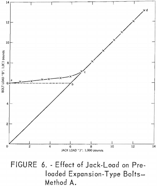
The effect of load applied by the jack on preloaded bolts is shown in figures 6 and 7 for test methods A and B, respectively. These curves represent the average bolt load-jack load relationship for the 40 tests using each method of testing.
The hypothetical graph o-d in figures 6 and 7 indicates what the bolt load versus jack load relationship would be if the test bolt had not been preloaded. Similarly, the graph abed represents what the relationship would be if the test bolt had been preloaded to 6,000 pounds and the load applied by the jack had no effect on the bolt load until the washer pulls away from the bearing plate (method A) or the bearing plate becomes loose from the roof (method B). The results of these tests indicate that the true bolt load-jack load relationship is actually similar to the curve acd. As the jack load is applied, the true bolt load which is indicated by the load sensitive bolt is increased by a fraction of the applied jack load until the two loads become equal at point c. Therefore, until the jack load is equal to the load at this point, the true bolt load can only be determined by using strain gages. These results correspond with those obtained during studies on the effect of testing preloaded slotted-type bolts.
To determine the fraction of the jack load that is added to the initial bolt load until the jack load and bolt load are equal, it is necessary to calculate the slope of the straight line that approximates curves a-c. The true bolt load is given by the following equation:
B = Bi + CJ……………………………………………………….(1)
Where B is the bolt load, Bi the installed load, J the jack load, and C the slope of the straight line that approximates curve a-c.
Table 1 gives individual values of C determined from 80 tests in sandstone and shale using 4-foot and 6-foot-long bolts. The differences in the values of C are small when varying the bolt length and the rock type. However, a significant difference is apparent in the value of C for the two methods of testing. The average amount that the bolt load increased as the
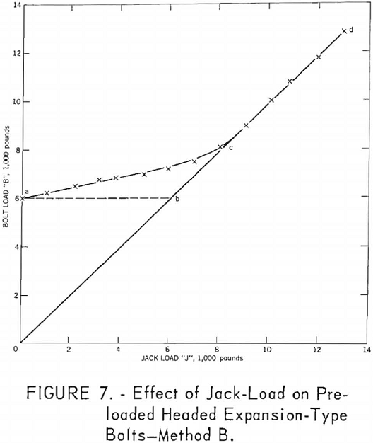
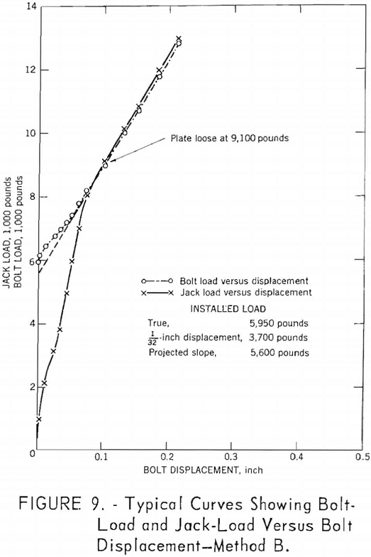
jack load was applied in method B was almost twice that obtained when using method A. In other words, the bolt load and jack load become equal at a lesser load when the pressure column presses against the bearing plate (method A). Therefore, method A is considered more suitable for making a conventional anchorage test, because it provides more data for evaluating the anchorage characteristics of the bolt.
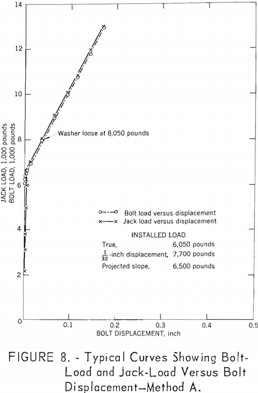
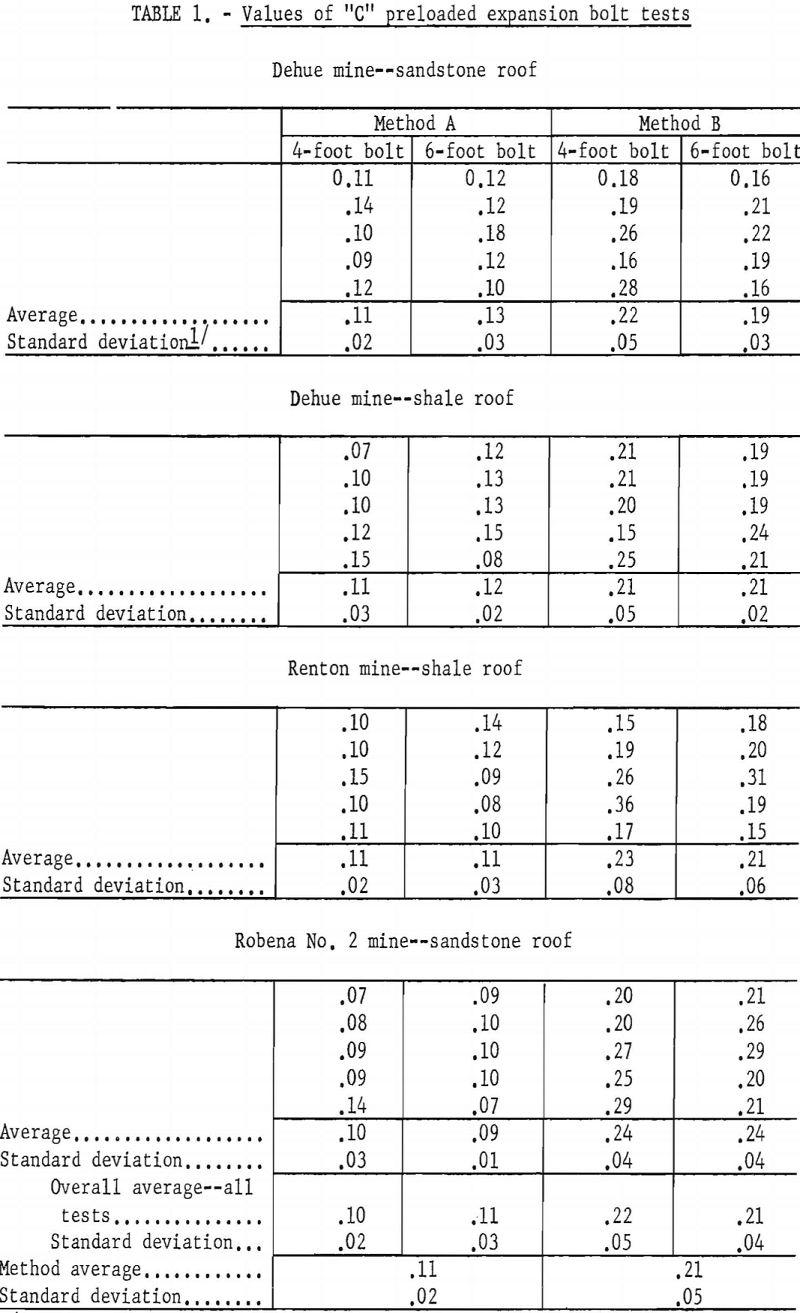
Figures 8 and 9 show typical bolt load versus bolt displacement and jack load versus bolt displacement curves for both testing methods. These curves further illustrate the difference in the effect of the jack load on the bolt load due to the method of testing. For example, in figure 8, the test bolt was installed at 6,050 pounds. The jack load was applied using method A and the two loads became equal at approximately 7,000 pounds. In figure 9, the bolt was installed at 5,950 pounds. In this instance, the jack load was applied using method B and the bolt load and jack load did not become equal until approximately 8,200 pounds was reached. These results indicate the need for a method of determining the point at which the two loads are equal when making a conventional anchorage test.
As previously stated, one procedure to determine when the jack load equals the load in the bolt, is to note the load at which 1/32-inch bolt displacement occurs. The results of these tests indicate that this estimate is approximately correct when test method A is used, but the error in the estimate might be quite large when using test method B. For example, in the typical curves presented in figures 8 and 9 for methods A and B, respectively, the load sensitive bolt indicated that the true bolt load was equal to the jack load at 7,000 pounds in figure 8, and 8,050 pounds in figure 9. If the point at which 1/32-inch bolt displacement occurred was used, the results would be 7,700 pounds and 3,700 pounds, respectively.
The second procedure described for making the determination is to note the load when the first abrupt change occurs in the slope of the jack load- bolt displacement curve. Figures 8 and 9 show that if this procedure was followed, the two loads would be considered equal at 7,000 and 8,050 pounds respectively. This second procedure is acceptable, because these values are the same as those indicated by the load-sensitive bolt.
Another way to determine the point at which the two loads are equal is to note the point where the hardened washer becomes loose when using test method A or to note the point where the plate becomes loose in test method B. As shown in figures 8 and 9, the loads obtained by this procedure were 8,050 pounds and 9,100 pounds, respectively. Despite the fact that both of these values are about 1,000 pounds above the point at which the two loads actually become equal, this procedure is still considered acceptable. The error involved, if any, will always be on the safe side, that is, the estimate always will be greater than the true value. Determination could have been estimated more accurately if the washer or plate had been tapped more frequently as the load was applied, instead of after each 1,000-pound increment of load was added.
Determination of Anchorage Characteristics
The results of these tests indicate that when determining the anchorage characteristics of any roof bolt and shell assembly from a plot of jack load versus bolt displacement data; the data obtained before the bolt load and jack load became equal should be disregarded and conclusions based on the data obtained beyond this point. The reciprocal of the slope of this portion of the curve will indicate the bolt displacement per increment of added load and the anchorage capacity if it occurs before the yield point of the bolt is reached. For example, in figure 8 the bolt load and jack load are considered equal when the washer became loose at a load of 8,050 pounds. The bolt was then loaded to a maximum of 12,950 pounds and the bolt displacement increased from .039 inch to .171 inch. For an added load of 4,900 pounds, the bolt displacement amounted to .132 inch or .027 inch per 1,000 pounds. In figure 9, the bolt load and jack load are considered equal when the plate became loose at 9,100 pounds. The bolt was loaded to a maximum of 12,950 pounds and the bolt displacement increased from .101 inch to .215 inch. For an added load of 3,850 pounds, the bolt displacement amounted to .114 inch or .029 inch per 1,000 pounds. Generally, a smaller value (bolt displacement per 1,000 pounds) indicates a better anchorage providing the comparison is made between bolts of the same dimensions which are loaded over the same range. In both cases cited, the anchorage capacity was greater than 12,950 pounds, because there was no rapid increase in bolt displacement for each increment of load added.
Determination of Installed Load
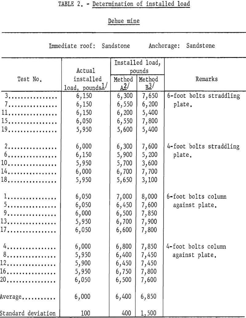
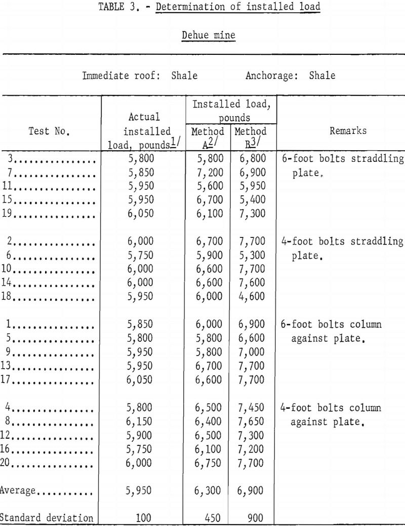
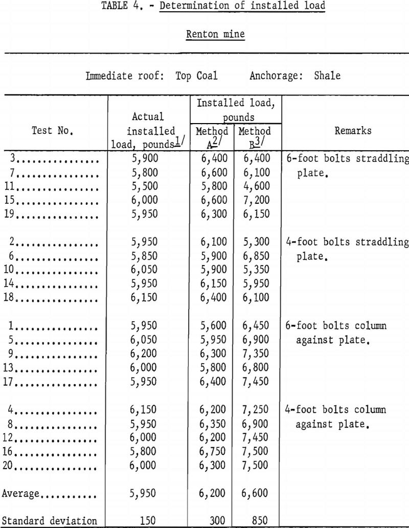
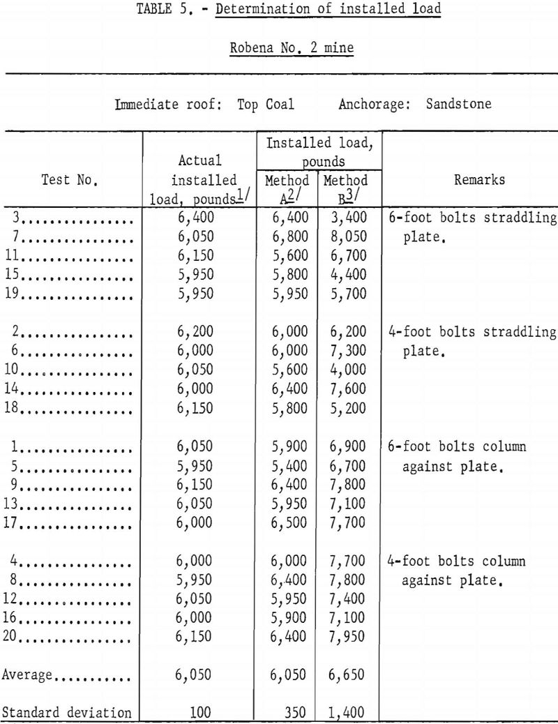
Tables 2, 3, 4, and 5 compare the results obtained for the installed load when determined by the load-sensitive bolt with those obtained when using the procedures previously described. Figures 8 and 9 illustrate how these values were determined in a typical test.
In figures 8 and 9 the true installed load as indicated by the load-sensitive bolt was 6,050 pounds and 5,950 pounds, respectively. If the installed load had been determined by noting the load at which 1/32-inch bolt displacement occurred; the values obtained would be 7,700 pounds in figure 8 and 3,700 pounds in figure 9. When the installed load was determined by projecting the slope of the jack load-bolt displacement curve back to the zero displacement or vertical axis the values obtained were 6,500 pounds and 5,600 pounds, respectively.
These results indicate that the error can be quite large when using 1/32-inch-bolt displacement as the criterion for installed load when using either method of testing. The error in the approximation is relatively small when projecting the slope of the jack load-bolt displacement curve to determine the installed load.
