Table of Contents
I once used an Anemometer to Measure Flotation Cell Air Flow on Self Aspirating WEMCO machines. Overtime, operations & maintenance got lazy and never took care of cleaning the airflow supply pipe into the cell. It was clear flows were partially to completely blocked.
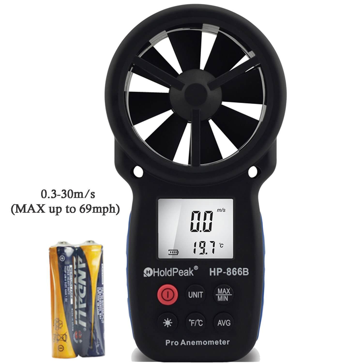
I improvised the method and now found one the US Bureau of Mines had written was back. Measuring the air flow with an Anemometer gave me a relative idea of cell blockage which affected air supply and therefore recovery. There is nothing scientific about the method/technique I used. I just bought a $25 Anemometer on Amazon and held it just at the air-inlet to get a reading.
I built some kind of model to estimate the airflow impact. Inhere in a paper by the US Bureau of Mines doing something similar of any pipe + later down the page is my test report.
The technique provides the mining industry with a simple, accurate and readily available means of measuring the gas flow from pipe outlets such as gob holes. The Bureau of Mines conducted laboratory studies to establish correction or method factors for anemometers when used to measure gas flow from pipe outlets.
Using the Anemometer
Anemometers are used by the mining industry to make air velocity measurements in mine entries. Although the instrument has no appreciable influence on the airstream in mine entries, especially since the cross-sectional area of an entry is much larger than the cross-section of the anemometer, correction or method factors are used to correct the center line anemometer velocity to average velocity. This adjustment is made because the air velocity in a mine entry is highest in the center and lower at the sides. Anemometers can be used to measure gas flow from small diameter pipe outlets; however, since the instrument diameter is much larger than one-sixth of the pipe diameter, it will influence the air-stream from these small outlets. Resulting velocity measurements are erroneously high by as much as 30 percent. Method factors must be applied to such anemometer measurements taken at pipe outlets. Through a research investigation, the Bureau of Mines established a set of method factors for center-line anemometer readings taken at the discharge end of 4- to 8-inch diameter pipes. These method factors were combined with method factors which were developed by the National Coal Board of Great Britain for 12- to 30-inch diameter pipes. The anemometer was mounted on the end of a short rod and held against the pipe for support except on the 4-inch pipe where the instrument was started and stopped remotely to prevent hand interference with the air-stream during measurements. Method factors were determined by comparing the anemometer measurements at the pipe outlet to the true average airflow which was simultaneously determined upstream by venturi measurements. Consequently, a method factor is nothing more than the ratio of the true velocity to an anemometer measurement.

Method factors were determined for a wide range of flows for each pipe size. The data were analyzed statistically to determine an average method factor for each size.
Method Factor Range
Method factors range from 0.68 for 4-inch pipe to 0.85 for 18- inch pipe. For pipe sizes larger than 18 inches and for mine entries, the method factor is 0.85. These data indicate that the anemometer, when used to measure gas flow from a pipe outlet, always measures an average velocity that is much greater than the true average velocity. For pipe sizes from 4 to 18 inches, the anemometer tends to cause air restriction. Because mass flow must be conserved, the velocity through the restriction increases, and consequently the anemometer records a velocity that is much greater than the true velocity. For pipe sizes greater than 18 inches and for mine entries, the anemometer registers the centerline velocity which must be multiplied by 0.85 to obtain the average velocity.
Buy an Anemometer
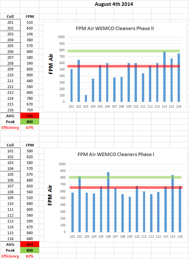
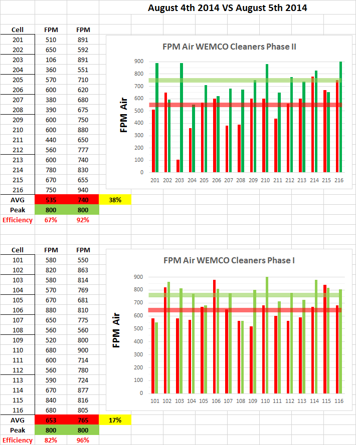
On July 28th, a survey of airflows to each WEMCO rougher cells was performed. Its data is graphed below:
 Because many Units (Cells) are shutdown or have their airflow restricted, the ‘Average’ airflow throughout each bank is 800CFM. Using 1300 CFM as the maximum airflow, the effective efficiency of the rougher banks can be approximated at 63% and 82% for the Pre-Cleaners.
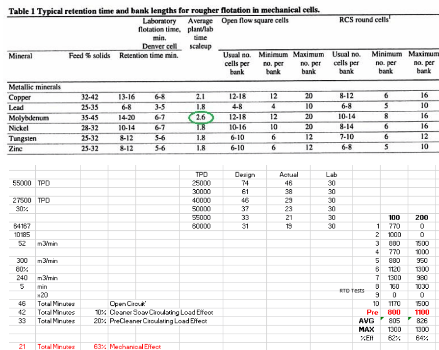
Below is a Chart of Designed and Actual (considering poor airflow and mechanical breakdowns) Flotation RTD for various Tonnages. Those two data set are graphed against Laboratory Work and Textbook scale-up factor of 3X.
Also included in the Chart is an ‘all units working’ Plant RTD (Dye Tracer) test performed at 40,000 TPD which helps support the model.
The data below does not account for slower kenitics caused by coarser grinds at higher tonnage. It assumes 30% flotation feed density, 80% gas hold-up and around 25% cleaner/pre-cleaner circulating load.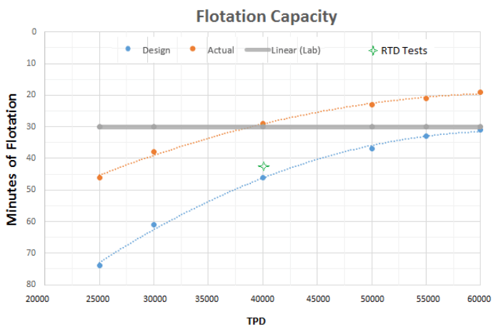
The Blue Line (Design) shows that when all cells are working with ‘full airflow’, the Plant has adequate flotation residence time for up to 60,000 TPD.
The Orange Line (Actual) shows the current ‘broken’ system comes short on residence time starting at 40,000 TPD.
This RTD model might help explain the lower recoveries achieved most recently while passing higher tonnages.
Below are 2 graphs on Moly and Copper Recoveries VS Tonnages for July 2014 in which the 40,000-45,000 TPD inflection point can be seen.
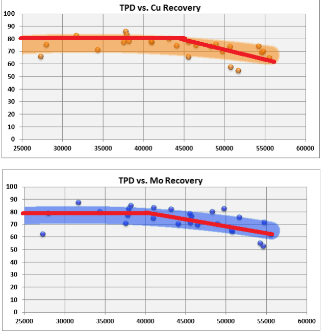
A Grind VS Flotation Kinetics is underway to complement this data.
Conclusion
All WEMCO cells should be brought back to their original state in order to help sustain metal recoveries at higher tonnages.
