Table of Contents
Chrome Recovery Plant Design: The purpose of the design phase of this project was to prepare the preliminary design of a pilot plant capable of:
- treating an average of at least one hundred pounds per hour of metallic scrap, and
- recovering a minimum of 65 percent of the contained chromium and other valuable metals (for example nickel and cobalt) in a state sufficiently pure to provide marketable materials.
The pilot plant would be a necessary next step to test the proposed process on a larger scale in order to verify technical feasibility and to determine commercial feasibility of the overall process.
Process Description
Based on laboratory data derived from this investigation and on published data sources, as discussed previously in this report, it is proposed that chromium and other critical metals be
![]()
recovered from superalloy scrap using a pyrometallurgical batch process comprised of the following steps:
- scrap melting;
- oxidation of metallic chromium to chromium oxide;
- slag/metal separation to yield a chromium-bearing slag phase and a metal phase containing iron, nickel and cobalt;
- reduction of chromium oxide in the slag to metallic chromium;
- slag/metal separation to yield a feirochromium product and a chromium-depleted slag phase.
As envisioned, the overall process is a batch operation employing a single electric furnace in which all process steps are performed.
Flowsheet and Operating Sequence
A schematic diagram of the proposed pilot plant operation is shown in Figure 11. As indicated, weighed allotments of superalloy scrap are charged to an electric arc furnace in which the scrap is melted. Once a molten bath has been achieved, flux materials are charged to the furnace, and the bath is injected with compressed air via bottom blowing or lancing (oxidation). During oxidation, chromium and other reactive alloying agents, such as manganese, tantalum and titanium (and, to some extent, iron), react with gaseous oxygen to produce metal oxides. These oxides will largely combine with the silica-lime flux to form a slag layer. Nickel, cobalt and the major portion of iron in the melt, will not combine with oxygen until the more reactive elements are oxidized, and will remain in the metal phase. Thus a separation is effected between chromium and nickel, cobalt, and iron.
Periodically during the blow, samples of the metal phase are obtained and analyzed for chromium content. Once the chromium level of the metal phase has been reduced to a sufficiently
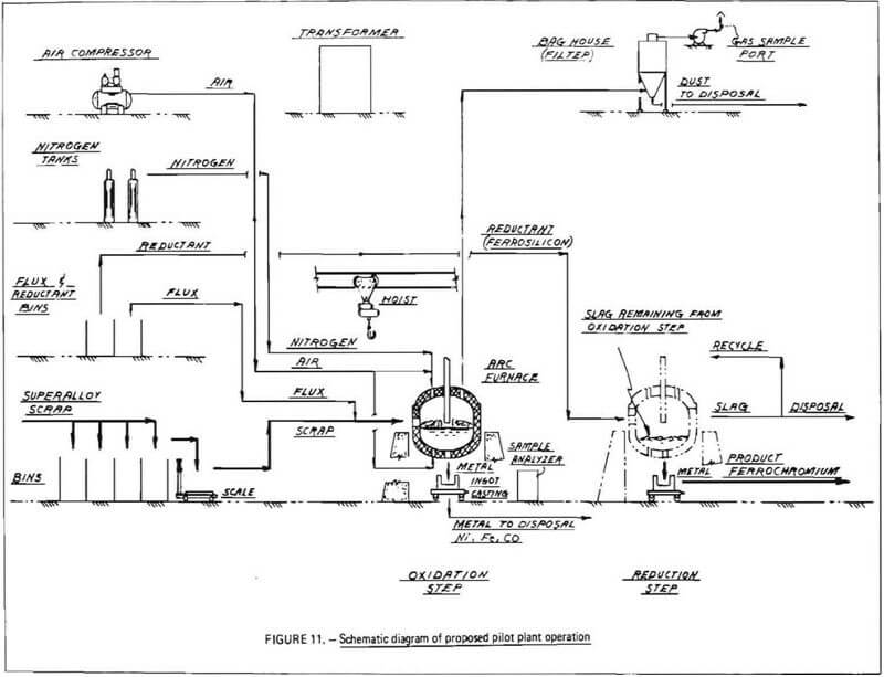
low level, the injection of compressed air is stopped, and an inert gas flow may be initiated to prevent further oxidation of the bath. The net result of the oxidation step is a chromium-bearing slag phase and a chromium-depleted metal phase.
A slag/metal separation is then performed. The furnace is tilted and, by means of a suitable slag gate, molten metal is poured off and cast into ingots. These ingots consist principally of nickel, cobalt and iron; the relative proportions of these elements will depend on the type of superalloy scrap charged to the furnace.
Chromium-bearing slag remains in the furnace. To ensure that the slag does not solidify, power is applied to the electrodes which can be operated either in open-arc or submerged-arc mode (during oxidation, the furnace is operated in an open-arch mode with electrodes above the bath to prevent possible reduction of chromium oxidized into the slag-phase). A reducing agent, such as ferrosilicon, aluminum or carbon, is charged onto the surface of the slag and allowed to react with chromium oxides, causing the formation of metallic chromium. Any iron present in the slag will also be reduced to the metal phase. In this manner, a ferrochromium layer will be produced. A final slag/metal separation is performed to recover ferrochromium product, which is cast into ingots. Chromium-depleted slag is poured out of the hearth and discarded.
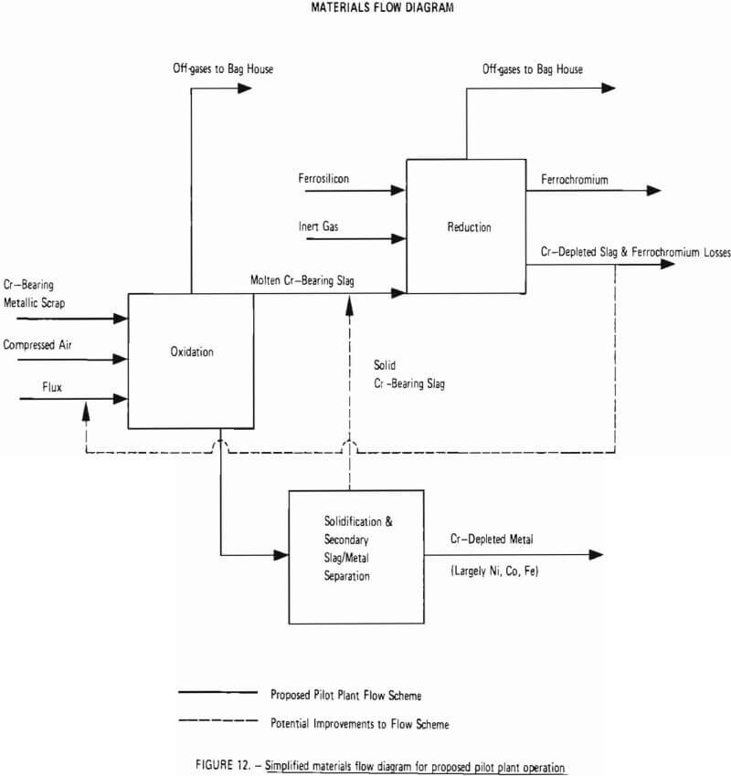
A simplified materials flow diagram for the process is given in Figure 12. This figure indicates materials flow through the two critical process steps: oxidation and reduction. Also shown is a “Solidification and Secondary Slag/Metal Separation” step in which chromium-bearing slag, unavoidably removed from the furnace with chromium-depleted metal (due to imperfect slag/metal separation at the slag gate) is separated from chromium-depleted metal in a ladle and transferred back into the furnace, thereby increasing overall chromium recovery. As indicated by dashed lines, this step represents a potential improvement to the process which is difficult to demonstrate on small-scale experiments and is best demonstrated at the pilot plant level. Another potential improvement to be tested during any optimization program (Phase III) is recycling of chromium-depleted slag (from the reduction step) back to the oxidation step as flux.
Environmental Issues
The largest waste stream from the electric arc furnace process is the slag phase consisting of fluxes added (lime and silica) as well as elements expected to oxidize in the proposed process (such as silicon, titanium, and aluminum). In addition to solid wastes generated in the form of slag, the electric arc furnace process emits gaseous and particulate pollutants principally during charging, melt-down, refining, tapping, metal transfer and teeming/casting. Scrap cleanliness and physical/chemical characteristics, as well as type furnace, size of furnace, and melt rate influence the quantity and type of emissions. For pilot-plant operations, the single electric furnace can be used in two modes, namely 1) as an open-arc (direct arc electrode) furnace, and 2) as a submerged-arc furnace. The open arc mode can be used for melting, oxidation of the chromium, and reduction by ferrosilicon, aluminum or possibly by carbon injection. As noted by the Environmental Protection Agency regarding the open-arc mode of operation:
“Electric furnaces are used primarily to produce special alloys steels or to melt large amounts of scrap for reuse. Heat is furnished by direct-arc electrodes extending
through the roof of the furnace. In recent years, oxygen has been used to increase the rate or uniformity of scrap-melt-down and to decrease power consumption.
“The particulates, primarily oxides of iron, manganese, aluminum, and silicon, that evolve when steel is being processed in an electric furnace result from the exposure of molten steel to extremely high temperatures. The quantity of these emissions is a function of the cleanliness and composition of the scrap metal charge, the refining procedure used (with or without oxygen lancing), and the refining time. As with open hearths, many of the particulates (40 to 76 percent) are in the 0 to 6 micrometer range. Additionally, moderate amounts of carbon monoxide (16 to 20 lb/ton) are emitted.
“Particulate control devices most widely used with electric furnaces are venturi scrubbers, which have a collection efficiency of approximately 98 percent, and bag filters, which have collection efficiencies of 99 percent or higher.”
An electric furnace operating in a submerged-arc mode is often called an electric smelting furnace. As noted by EPA in discussing ferroalloy production, the:
“most widely used electric furnaces are the submerged-arc open type
“The production of ferroalloys has many dust-or fume-producing steps. The dust resulting from raw material handling, mix delivery, and crushing and sizing of the solidified product can be handled by conventional techniques and is ordinarily not a pollution problem. By far the major pollution problem arises from the ferroalloy furnaces themselves. The conventional submerged-arc furnace utilizes carbon reduction of metallic oxides and continuously produces large quantities of carbon monoxide. This escaping gas carries large quantities of particulates of submicron size, making control difficult.
“In an open furnace, essentially all the carbon monoxide burns with induced air at the top of the charge and CO emissions are small.”
Thus, in general, the major air pollution abatement problem is found in and around the electric furnace as a result of the high temperature operation, which is capable of generating metallic fumes in the submicron sized range. The collection and removal of these particulates prior to discharge of gases to the atmosphere will be required.
Components of an effective arc furnace emission control system include:
a) emissions gathering by hoods and/or direct evacuation,
b) pre-treatment of the offgases usually for temperature control, and
c) ducting to a collection unit.
As noted, particulate emissions from arc furnaces are most frequently controlled by venturi scrubbers and fabric filters; however, high energy condensing systems have been used in some cases. For pilot-plant operations, it is proposed that a fabric filter (bag house) be used. Provisions will be made for sampling the offgases during extended tests. Particulates collected from air streams become part of the solid wastes generated in the facility. (If wet collection systems are used for particulate removal, there may be an additional need to control wastewater effluents. However, water is usually used in non-contact applications and thus would present no discharge problems unless special restrictions are applicable at a specific site.)
Slags and dusts are normally land filled. Because of the high metal content of these solids, special attention should be given to preventing acidic leaching conditions from occurring and to ensure that the design and operation of the approved landfill is in accordance with regulations being developed under the Resource Conservation and Recovery Act (RCRA). The electric arc furnace process is the predominant technology used today in recycling scrap ferrous metals to produce steel of various grades. Nearly all the elements found in scrap superalloys are being used by steelmakers in electric furnaces. Thus, emissions or discharges from the proposed chromium recovery process are not expected to be significantly different from those already of concern to the iron and steel industry. Although the ratio of elements found in the dusts and slags may be different, other new toxic and hazardous pollutants are not expected to be of any concern.
A detailed description of environmental issues in the iron and steel industry and pollution control technologies can be found in reference 1.
Projected Materials Balance
In order to properly size equipment, it was necessary to prepare a projected materials balance for the proposed pilot plant operation. Because of the variability of feedstock composition associated with this process, as evidenced by the range of superalloy scrap composition given in Table 2, two projected materials balances were prepared: one based on a feedstock composition given by the calculated weighted average composition of wrought nickel- and cobalt-base superalloy, the other based on a feedstock composition given by the calculated weighted average composition of wrought nickel-iron based superalloy. The justification for selecting these two average compositions for projected materials balances was:
- Scrap survey data (Table 1) show that wrought nickel and cobalt alloys and wrought nickel-iron alloys represent major current and projected sources of obsolete scrap.
- Both low-iron alloys and high-iron superalloys are represented by these two classes.
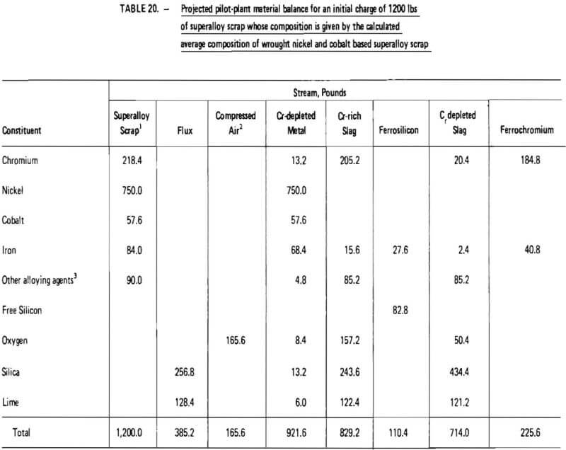
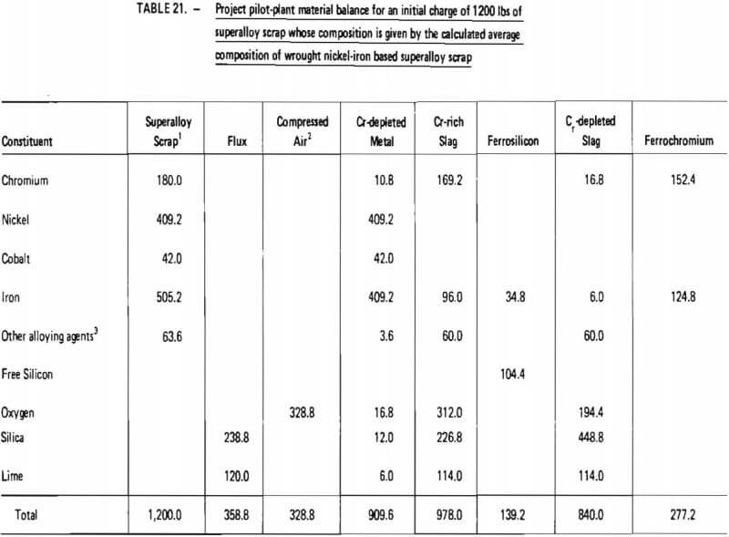
Projected materials balances for these two cases are given in Tables 20 and 21. These material balances were calculated based on:
- twelve hundred (1200) pounds of superalloy scrap;
- ninety-nine (99) percent removal of chromium from superalloy scrap during oxidation (see Table 14);
- partial oxidation of iron present in the initial melt (this is believed to be a conservative assumption since test data, given in Table 14, indicate there is a possibility of oxidizing chromium without oxidizing iron);
- complete oxidation of other alloying elements
5. no oxidation of cobalt or nickel present in the initial melt (Table 14);
6. the addition of sufficient flux so that final chromium-rich slag contains a maximum of twenty-five (25) percent by weight chromium;
7. five (5) percent loss, by weight, of chromium-rich slag due to an imperfect slag/metal separation following oxidation;
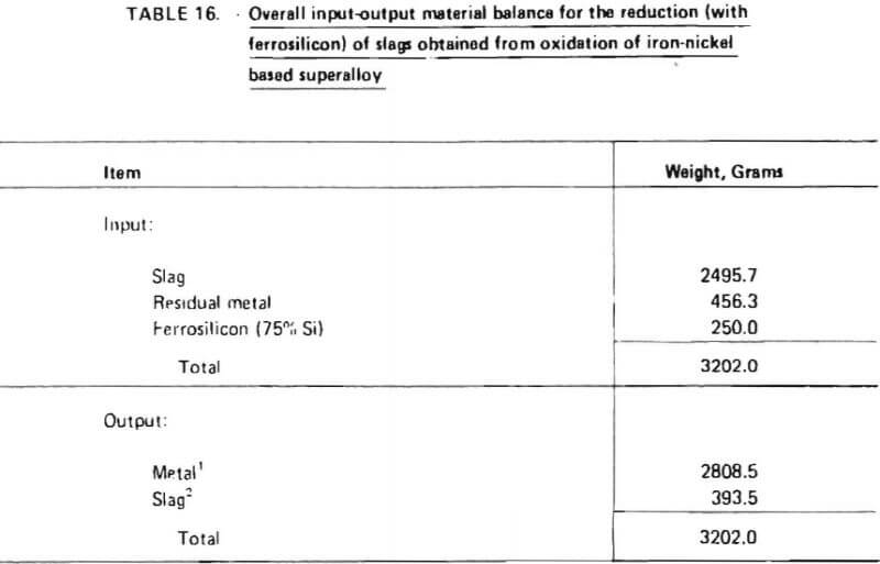
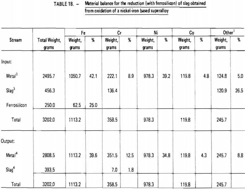
8. ninety-five (95) percent recovery of chromium from chromium-rich slag during reduction with ferrosilicon (Table 18); and
9. five (5) percent loss, by weight of ferrochromium produce due to an imperfect slag/metal separation following reduction,
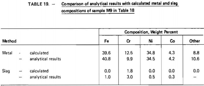
Items 2 through 5 and 8 above are justified in view of the experimental test work performed in this investigation as summarized in Tables 14 and 18, Items 7 and 9, which significantly affect overall chromium recovery, were based on engineering judgment. (The exact amount of chromium lost due to imperfect slag/metal separations cannot be quantitatively defined at this point and must be determined from actual pilot-plant operating data. Furthermore, the influence of slag volume on chromium recovery should be explored in a pilot plant program.) Item 6 represents an assumption based on experience obtained during laboratory experiments. Since these experiments were performed in an induction furnace in which slag characteristics (particularly viscosity) were difficult to control, the validity of this assumption is difficult to assess. It is conceivable that much lower flux consumption rates could be obtained in an operating pilot plant. However, the assumption does provide an upper limit for flux consumption and therefore represents a “margin of safety” for pilot plant design.
As indicated in Table 20, the processing of 1200 lb of “average” wrought nickel- and cobalt- base superalloy scrap would require 165.6 lb of oxygen (at 100% oxygen utilization), 385.2 lb of silica-lime flux and 110.4 lb of ferrosilicon (75% SI). Nine hundred and twenty two (922) lb of chromium-depleted metal would be produced, consisting primarily of nickel. It is projected that 225.6 lb of ferrochromium would be produced with a Cr/Fe ratio of 4.5. Overall chromium recovery is estimated at 84.6 percent.
Similarly, as shown in Table 21, the processing of 1200 lb of “average” wrought nickel-iron based superalloy scrap would require 328.8 lb of oxygen, 358.8 lb of flux and 139.2 lb of ferrosilicon. Nine hundred and ten (910) lb of chromium-depleted metal would be produced, consisting primarily of iron and nickel. It is projected that 277.2 lb of ferrochromium would be produced with a Cr/Fe ratio of 1.2. Overall chromium recovery is estimated at 84.7 percent.
Equipment and Layout
A major equipment list, developed for batch processing in the proposed pilot plant, is shown in Table 22. The equipment was sized so that the pilot plant would be capable of processing 1200 pounds of superalloy scrap in a total period of no longer than 12 hours, resulting in an average scrap throughput of at least 100 pounds per hour. A preliminary layout of the proposed pilot plant is given in Figure 13.
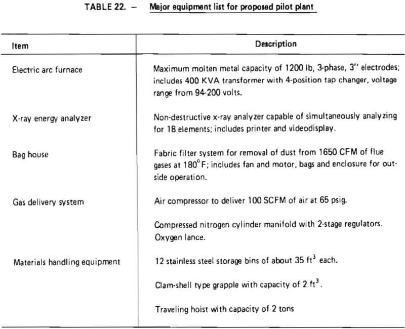
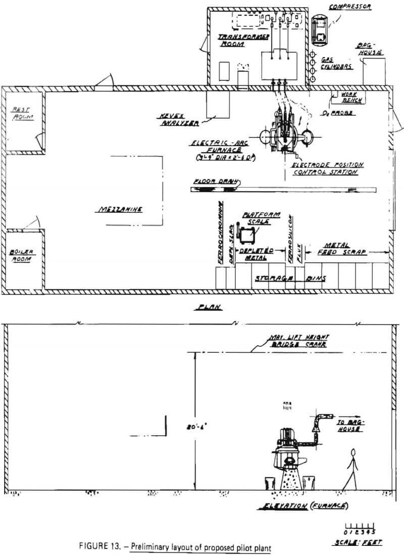
At the heart of the operation is an electric arc furnace with a maximum molten metal capacity of 1200 lbs. The furnace was selected because a survey of vendors indicated this size is the smallest electric arc furnace manufactured domestically at the present time. The furnace has inside shell dimensions of 3′-4″ in diameter with a 2′-6″ depth. It is equipped with 3-phase, 3” electrodes with an automatic electrode raising mechanism. Importantly, the furnace can be operated in direct-arc mode (for either oxidation or reduction) and submerged-arc mode (for reduction). The furnace is door charged and has a pour spout for metal remove and a slag door for slag removal.
Discussions with the manufacturer indicated that the furnace could handle a maximum of 1200 lbs of an initial superalloy charge and be able to contain the respective volumes of slag and metal phases during oxidation and reduction steps. However, for a maximum charge of 1200 lbs, some modification of the slag door and pour spout might be necessary to increase the working volume within the crucible. These modifications were described as being relatively simple, and quite commonly found in the ferroalloy industry.
Associated with the furnace is a 400-Kva transformer with a 4-position tap changer and a voltage range from 94-200 volts. The transformer includes disconnect switches, a circuit breaker and an operator’s metering panel, and can be operated on a 60 Hz frequency.
For sample analysis, an X-ray energy analyzer was selected. This device is capable of detecting, in as little as five seconds, the concentrations of up to 18 elements in a metal sample. It would be used to monitor chromium removal during oxidation (thereby determining reaction endpoint) and to follow the reduction reaction. For ease of operation, the analyzer is equipped with a video-display and a hard-copy printer.
To ensure that adequate test data can be obtained on particulate discharge from the furnace, a bag house filter system was sized and selected. Flue gases will be collected immediately above the furnace and diluted with air (for cooling). The mixture will pass through the bag house prior to discharge to the atmosphere. The filter system was designed to handle 1650 CFM at 180 °F and includes fan and motor, bags, and an enclosure for outside operation.
Other major equipment for the proposed pilot plant include a gas delivery system and materials handling equipment. The gas delivery system is composed of two sections: a nitrogen flow system (inert gas) and an oxidizing gas flow system. The inert system consists simply of a manifold (with regulators) to supply a controllable flow of Na into the furnace. The oxidizing gas system consists of an air compressor (capable of delivering 100 SCFM of air at 65 psig) and a suitable lance. The lance will be injected into the furnace through the charging door.
The materials handling equipment includes storage bins for superalloy scrap, flux, ferrosilicon and products (Cr-depleted slag, Cr-depleted metal and ferrochromium). An overhead hoist and a bucket will be used to charge the electric arc furnace. Products will be poured from the furnace into molds and transferred to their respective storage bins with the overhead hoist.
Estimated time periods for individual process steps, as well as a description of each step, are given in Table 23. The batch nature of the proposed operation is evident from this table.
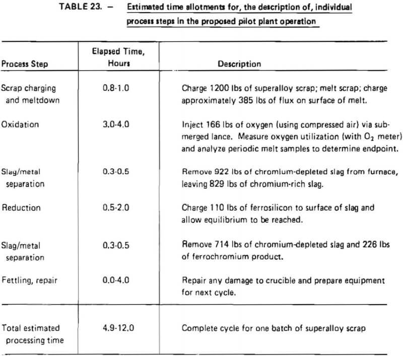
Time periods were calculated such that a high degree of flexibility could be achieved in pilot plant operation. As indicated in Table 23, 0.8 to 1.0 hours are estimated to be necessary to melt down a maximum charge of 1200 lb of superalloy scrap, based on transformer output. Oxidation time is estimated to be 3 to 4 hours with reduction taking anywhere from 0.5 to 4 hours. These periods were conservatively estimated based on experience gained in laboratory tests. Discussions with the furnace manufacturer indicated that a slag/metal separation would take about 0.3 to 0.5 hours, whereas 0.0 to 4.0 hours might be required to repair refractory linings after a process cycle.
Total processing time is estimated to range from 4.9 to 12.0 hours, equivalent to an average scrap throughput of 100 to 245 lb/hr. Equipment was sized to achieve maximum throughput as dictated by the minimum elapsed processing time shown in Table 23.
Pilot Plant Construction
Capital Cost Estimates
Capital cost estimates for detailed design and construction of a pilot plant facility capable of demonstrating chromium recovery from superalloy scrap were developed according to the methodology used by Phillips. For this type of estimate, known as a “study estimate”, preliminary materials balance and plant layouts are employed to describe the plant. Major processing and auxiliary equipment are listed by type, size, material specification and utilities requirements, Purchased costs for this equipment are then compiled from published sources such as sales catalogues and technical literature (which commonly give cost-capacity relationships), from discussions with equipment vendors and from in-house data and engineering judgments. Because of the relatively small scale of this particular operation, cost-capacity relationships were not suitable for accurate cost estimates; hence, principal sources were telephone discussions with equipment manufacturers.
It was assumed in preparing cost estimates that the pilot plant would be constructed at an existing pilot plant facility with adequate headroom for a traveling hoist, a concrete slab floor with ample available floor space and electric substation capacity of 1000 Kva; provisions for none of these items were included in the cost estimates.
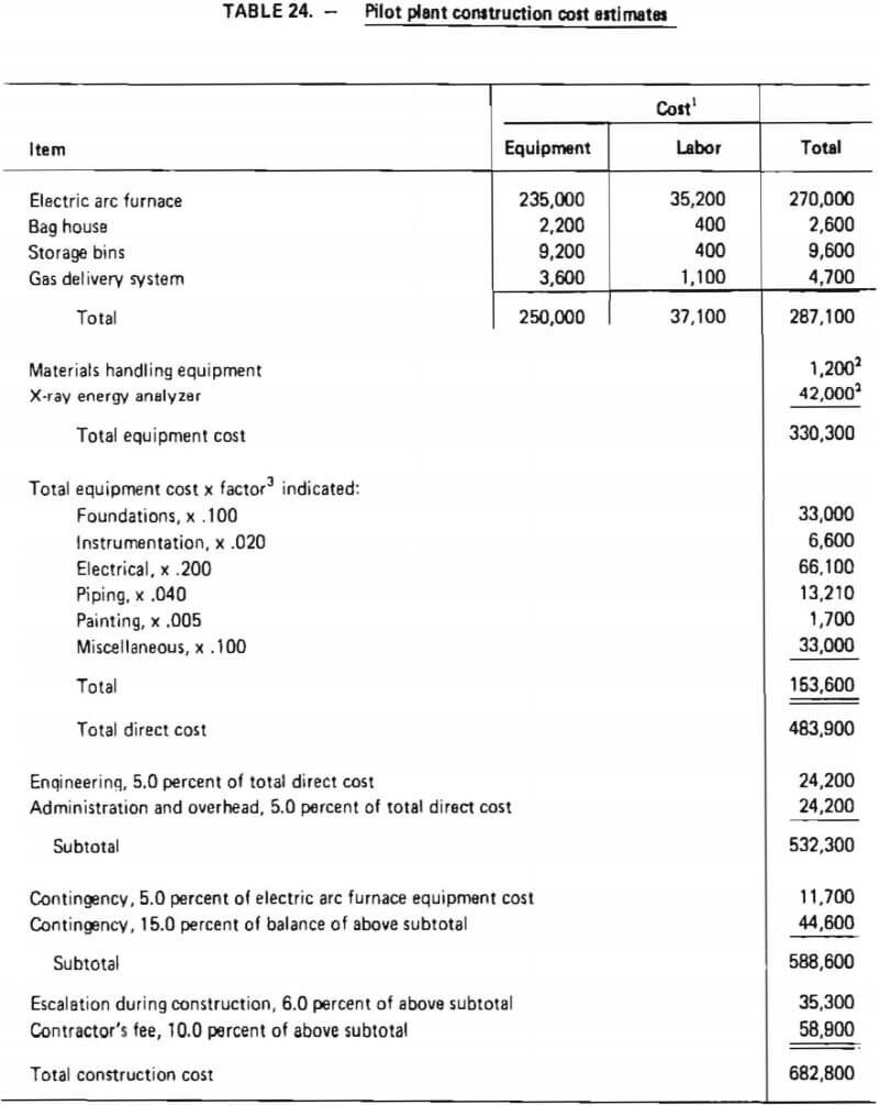
A major equipment list has been given in Table 22. Total pilot plant construction costs are developed in Table 24. These costs are based on estimated delivered equipment costs and factors which represent average costs to engineer and install the equipment. Weaver and Bauman, Pikulik and Diaz and Popper provided insights into factor values. Experience of the authors indicated that the factors from these referenced documents must be modified for use in construction of the pilot demonstration plant; factors were therefore adjusted based on past experience and engineering judgment to account for:
- the relatively small size of the operation;
- the existence of a present pilot-plant facility with existing utilities and provisions for services such as contracted solid waste disposal;
- the small proportion of materials handling equipment; and
- the large proportion of the total cost associated with a single piece of equipment, namely the electric arc furnace.
As shown in Table 24, the total installed equipment cost is $330,300. After considering “miscellaneous” items, to account for minor process and auxiliary equipment as well as materials required during construction which were not listed separately, total construction cost was estimated to be $682,200. This includes two “contingency” factors which allow for uncertainties in estimated costs. Because the estimate of the electric arc furnace was considered a “firm estimate,” a contingency of 5% was assigned to its delivered cost. Weaver and Bauman concur that an uncertainty of ±5% is appropriate for a “firm estimate.” The remainder of the total construction costs are less well defined and therefore are assigned a contingency of 15 percent. Weaver and Bauman suggest a contingency of 20-30 percent for a plant at this stage of design and development; nevertheless, a 15 percent contingency was thought to be more appropriate due to the small amount of auxiliary equipment which would be required to operate this process in an existing pilot-plant facility.
Construction Schedule
An estimated construction schedule for the proposed pilot plant is shown in Table 25. As indicated, the longest elapsed time is associated with the delivery of an electric arc furnace (5-6 months). Total elapsed construction time is estimated to be 6-7 months. This includes time for detailed engineering, site preparation and installation of equipment.

Technical Issues
Two technical procedures were difficult to demonstrate on the small-scale induction furnace experiments of the present program and deserve primary attention in pilot-plant experiments:
- Ensuring, in a simple fashion, good oxygen-metal contact during chromium oxidation is essential. It is proposed that future pilot-plant experiments be conducted in an electric arc furnace to ensure a high temperature slag to promote fluidity. Oxygen lancing onto the top surface of the melt is proposed as the simplest method of achieving chromium oxidation. If this should prove to be inefficient, submerged air injection into the molten metal bath is recommended either by a consumable lance or by introduction through the side walls of the furnace as has been practiced in steelmaking (as, for example, at Sidney Steel in Nova Scotia or Armco Steel in Houston, Texas).
- The amount of air to be introduced to oxidize chromium depends on initial scrap metal composition and degree of oxygen utilization. It is proposed that an oxygen analyzer (for the offgases) and an x-ray analyzer (for the metal phase samples) be used to determine when the chromium has been oxidized out of the metal phase.
In addition to these two technical procedures, it is also proposed that the separation between chromium and minor alloying agents in superalloy scrap (such as tungsten, molybdenum, and tantalum) be studied in detail on the pilot-plant scale. Data obtained in this investigation indicate that these other alloying agents tend to report to the slag phase during oxidation. Although appropriate Cr/Fe ratios have been indicated for final ferrochromium product in these experiments, the purity of ferrochromium with respect to other elements has not. Hence, it is important that detailed chemical analysis of intermediate and final products (that is, accounting for specific alloying elements such as Mo, Ta, W, Al) be carried out during pilot-plant demonstrations so that the distribution of these elements in final products, particularly ferrochromium, can be determined.
Other issues, such as reduction of chromium from the slag phase, degree of slag-metal separation that can be achieved, and refractory use, are clearly important but are judged to be less critical in that they have been demonstrated in past work and in prior commercial practice.
Conclusions
Data obtained from the experimental program indicated that:
- It was possible to oxidize and remove chromium from a variety of chromium-bearing scrap types regardless of the other alloying constituents present. Chromium removals exceeding 99 percent could be achieved. There was no evidence of nickel or cobalt oxidation while chromium is oxidizing. The results are consistent with theoretical thermodynamic principles used to devise the conceptual flowsheet for the process.
- As expected from commercial practice, no difficulty was experienced in reducing chromium oxide (in a slag phase) to chromium metal. It was possible using ferrosilicon to recover up to 95% of the chromium initially present in a slag phase.
- It was possible to obtain sufficiently good iron/chromium separation to produce ferrochromium product suitable for steelmaking. Using synthetic slags (that is, slags which were not produced in an oxidation experiment), a ferrochromium product was produced which contained 65% chromium.
- The proposed integrated pilot plant will have an estimated chromium recovery of 85%
Using these experimental results, estimated pilot plant capital investment is about $700,000 for a batch process to treat at least 1200 lbs in a period no longer than 12 hours.
Appendix A
The category of superalloys includes numerous alloy classifications. The variety and complexity of these combinations requires a more complex methodology for chemical analysis than would be necessary if only a limited number of elements were found in a given sample. A careful choice must be made of analytical method and sample preparation technique to assure that accuracy and precision are obtained for the key elements to be analyzed in samples which may vary widely in chemical composition.
The analytical work undertaken in support of the experimental program involved the determination of cobalt, chromium, iron, and nickel in superalloy scrap starting materials, intermediate reaction products and slags, and final product metals and slags. No single analytical procedure applicable to this variety of sample types and composition was available in the chemical literature. Thus it was necessary at the beginning of this project to develop an appropriate analytical procedure. This effort included a brief review of standard analytical methods ordinarily employed for similar analyses, selection of an appropriate analytical method, development of a suitable sample preparation procedure, and analysis of standard reference materials for the purpose of validating the resulting analytical methodology. Each of these steps is briefly described below.
Standard Analytical Methods
Emission spectroscopy and x-ray spectroscopy have generally been the analytical methods of choice in the industry because of their speed and resulting economy when large numbers of analyses of a single alloy type are to be made.
Emission Spectroscopic Procedures are applicable to the determination of all metallic constituents in ferrous alloys and are especially valuable for elemental concentrations below 0.1 percent. Various forms of solid samples or dissolved samples may be analyzed. Limitations include the need for careful standardization of procedures, the need for different calibration curves for each type of sample matrix, and the difficulty in determining high concentrations with accuracy and precision. Instruments employing plasma excitation sources have recently become commercially available and have reduced or eliminated many of these former disadvantages.
X-ray spectroscopy can be used for determining all but the lighter elements in ferrous alloys. It is better suited than older emission spectroscopic techniques to determine elements present in high concentrations. Volumetric, gravimetric, and colorimetric methods have long been associated with the analysis of certain metallurgical materials when multiple determinations of a single element are required. Prior separation to eliminate interferences due to the presence of one or more additional elements in the sample must usually be effected when these methods are used. The accuracy, precision, and selectivity obtainable with atomic absorption (AA) spectrometry are considered to be competitive in many cases with classical techniques, with the result that this method has found increasing use in industry. A limitation of AA methods is that sample solutions containing high concentrations of analyte may need to be diluted several-fold to bring them into a concentration range appropriate for analysis.
Selection of Analytical Method
The analytical procedure selected should be capable of handling the anticipated concentrations range of Co, Cr, Fe, and Ni as shown in Table A-1. Of the analytical methods described above, plasma emission spectroscopy was identified as having the best combination of applicability to these concentration ranges, accuracy, precision, speed, and flexibility with respect to choice of elements for analysis. Thus, a plasma emission spectrometer equipped with a DC argon plasma excitation source was used for all the analytical work described in this report. Close matching of sample and standard matrices is much less critical than in other emission spectroscopic techniques, calibration is less extensive and is required less frequently, and the sample throughput is higher. A limitation of this technique is that samples must be in solution for presentation to the instrument. This necessitated an effort at the beginning of the project to develop an appropriate sample preparation procedure.

Development of Sample Preparation Procedure
Most ferrous alloys are dissolved by the common inorganic acids (HCl, HNO3, H2SO4), singly or in combination. However, the sampling technique used in this study to obtain samples of intermediate reaction products was expected to result in the possible presence of difficult soluble silicates in those samples. Slag samples were also expected to be resistant to acid attack. The need to assure complete dissolution of samples containing both free metals and silicates suggested that the use of a two-step sample preparation procedure including preliminary acid dissolution followed by fusion of insoluble matter was appropriate.
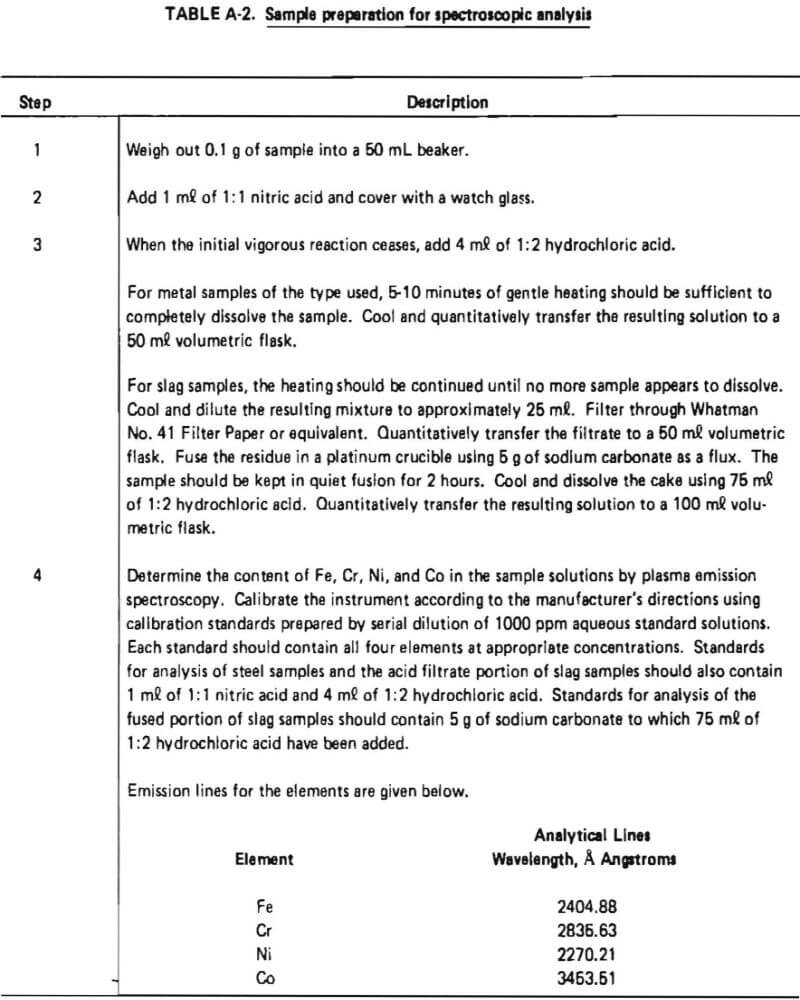
The acid dissolution procedure described in ASTM Method E 484-73, ‘‘Standard Method for Optical Emission Spectrometric Analysis by the Solution-Reservoir Cup Technique,” had been shown in previous work to provide complete dissolution of samples of structural steels. Preliminary qualitative tests on samples of superalloy starting materials indicated that this procedure gave clear solutions with no visible residue. Slag samples, however, were not completely dissolved by this acid treatment, so the classical sodium carbonate fusion approach for difficult soluble silicates was evaluated for dissolution of insoluble residue. This fusion approach was found to completely dissolve slag samples if the flux and sample mixture were heated for a minimum of two hours. The acid and fusion steps were combined with plasma emission spectroscopic analysis in the method described in Table A-2. This method was used for the analysis of all samples.
Analysis of Standard Reference Materials
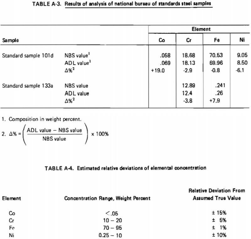
Two National Bureau of Standards Steel Samples were obtained and analyzed using the analytical procedure described in Table A-2. The results are shown in Table A-3. These results indicated that the relative standard deviation of the determined concentration for a given element could be expected to be within the indicated percentages of the assumed true value as given in Table A-4.
Summary of Analytical Procedure
The analytical procedure developed for this study included acid pre-treatment and fusion steps for sample dissolution followed by analysis by plasma emission spectrometry. The procedure was applicable to the ranges of sample types and compositions encountered. Detection limits estimated from the signal to noise ratios for actual sample solutions were on the order of 0.01 weight percent of the respective elements in metals and slags.
