Table of Contents
Upon nothing does the comfort of the inmates of a laboratory so much depend as upon the hood, and it is essential that this should “draw” well in order to carry off the fumes.
Simple Laboratory Fume Hood Design
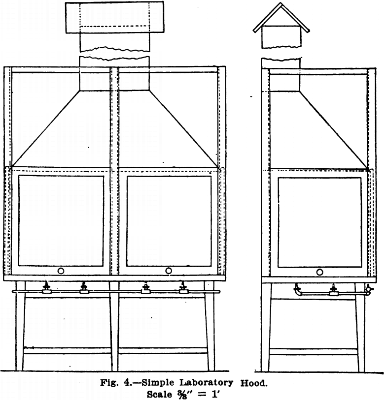
Fig. 4 shows the simplest form of hood and one which will draw best of all, because the hot gases go straight up without making any turns or bends. A hood opening into a flue warmed by chimney gases, even though the hood gases make a double bend, will usually draw. Indeed, for most work it is unnecessary to encase the sides of a hood built along these lines with sliding sashes. The writer designed some years ago for his use a hood which consisted merely of a stone topped table over which a sloping canopy top was constructed, like a hood to a blacksmith’s forge, with a straight flue leading up through the roof. This hood was not connected with the table in any way, even the corner posts being omitted. It stood against the wall. The table top measured 8 x 3 feet and the rim of the canopy stood 6 feet 2 inches from the floor, and projected 3 inches on all sides beyond the table top. This hood drew beautifully, and even sulphide precipitations could be made in it without even an odor of hydrogen sulphide escaping into the room.

The hood shown in Fig. 4 can be readily understood from the drawing. The dimensions of the hood are 6 feet by 3 feet. Its bottom stands 32 inches from the floor and the rim of the canopy top is 6 feet above the floor. In proportioning a hood, the height of the bottom from the floor should be such that the hot plates to be used are on a level with the top of the work benches. The rim of the hood canopy should be high enough from the floor not to touch the operator’s head when he stands erect under it. It is usually cheaper, also, to take stock-size sash-frames and design the hood to fit these rather than have special sash-frames made to fit the hood.
The hood shown is meant to go against the wall. If a square hood for the middle of the room is desired, the front and sides will be alike.
The sides of the hood shown are closed by sliding glass frames, which are mounted on Pullman spring balances, doing away with pulley weights, which make a much larger and more cumbersome framework necessary. In this hood the upper framework is made to merely rest upon the table top if this is of stone; otherwise it can be fastened to the top.
The hood shown in Fig. 4 is made with a table for a base. Instead of this, the hood can of course be mounted on a press or cupboard using the latter for storage of acids, apparatus, etc.
https://www.youtube.com/watch?v=L0PWExzbFpU
Fume Hood Concrete Top
The writer having had considerable experience with concrete, the idea of covering the floor of the hood with concrete instead of using a stone slab occurred to him some years ago. Where this is done, it is only necessary to put a wood top of rough plank on the table, making this top three inches nearer to the floor than the completed top is to be. Then put-on the super-structure and canopy part of the hood. Next finish off the rough edges of the table top and fasten tightly to this with thin screws a wooden rail, whose top is, 3 inches from the rough wooden top. Then fill in to the top of this wooden rail with concrete. The best mixture for this purpose is limestone screenings, using one part of cement to 3 of limestone screenings passing through a 1/8-inch screen. The advantage of using limestone screenings in place of sand is that any acids spilled in the hood will attack both the cement particles and those of the limestone, leaving an even surface; while if sand is used, only the cement is attacked, leaving a rough, uneven surface. The cement sand mixture is also more porous than the cement limestone. After the concrete is hard the rail can be removed, the screws greatly facilitating this. Another very serviceable floor for a hood is sheet lead. This can be cut to fit the wood bottom, allowing 3 or 4 inches for turning over and under the sides. One-sixteenth inch lead is thick enough and can be easily worked. The hood may also be lined with tiles or with ¼-inch asbestos board. The concrete mixture, however, is much cheaper than the latter and is far preferable to it.
Fume Hood Gas Taps
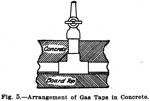
The gas taps for the hood should run around the front of the hood, as it is very inconvenient to reach over hot plates, etc., to turn them out; and at times it may be necessary to control the gas supply from outside the glass doors. The gas taps are usually placed as they are in Fig. 4, the rubber tubing passing to the interior of the hood through holes bored in the hood floor. If this latter is to be of concrete, before putting in this, cut 4 inch pieces of iron or brass pipe inch inside diameter and set in holes bored through the rough wood bottom so that their tops are level with that of the wooden rail. Another plan is to pass the tubing over the edge of the hood floor, in which event notches must be cut out of the sashes; or, since some air must always be admitted to the hood to form a current to sweep the fumes up the flue, a block or stop may be put in the frame for the sashes so that when closed the bottom of the sash is one or two inches from the stone slab. This is usually only done when a stone top which, has not been bored is used as a bottom. Where the top is-of concrete the gas piping may be first fitted and laid on the wooden top, the concrete then being placed over it, leaving only the tops sticking up, as in Fig. 5.
Fume Hood Canopy
In the hoods shown, the canopy part is built of ½ inch matched and grooved lumber. This is light and is not attacked by fumes. It is so far away from the burners as to be in no danger of catching fire. Where the room is not very well lighted this top may of course be made of glass; in which case, it is perhaps best to run the framework up to the ceiling and merely add a row of sashes, making a sort of glass box. The plastered ceiling should be covered with wood, however, as it is almost sure to be attacked by the fumes, dropping sand and lime into solutions, etc., evaporating below.
Lighting the Hood
If the laboratory is lit with electric lights, a few of these should be put in the hood. They should be held in a round porcelain base socket, without key, screwed to the frame, the wiring all being concealed and the lights turned on

and off by a switch on the outside. The metal work where the globe and socket join should be wrapped with insulating tape so that no metal is exposed. If gas is used, an ordinary fish tail burner in the centre of the hood, directly underneath the wood flue, will not only give the necessary light but will also help along the draft of the hood.
Mechanical Ventilation of Hoods
It occasionally happens that gases given off in the hood are heavier than air and will not rise. In this event, the gases must be drawn off at a level with the hood floor, by a small fan directly connected with a motor. Such a hood should be provided with a small sliding ventilator at the top, which may be opened, admitting fresh air into the hood when the fan is running. It is hardly necessary to say that such a hood should have sides.
Where a hood connects with a flue in the walls of the building it is sometimes hard to get a draft, particularly in summer time when the flue is cold. In such cases a lighted gas burner placed just inside the flue will help matters. The flue should also draw only from the hood. Draft can of course always be secured by fans; these are rapidly corroded by acid, however, and are expensive to operate. Where their use is necessary and fumes corroding metal are present, the writer suggests washing the gases by passing them up through a cylinder formed by a length

or two of sewer pipe. This is to be filled with coke, kept wet by water trickling over it, in order to wash out the corrosive gases, before they come in contact with the fan. The acid water could then be caught in a lead or earthen-ware receptacle at the bottom of the pipe and allowed to go to waste by drawing off occasionally. When high pressure air is available, a small hood may be ventilated by allowing this to flow through a small opening creating suction, see Fig. 6, on the principle of an injector.
