Table of Contents
- CCD Wash Ratio Definition
- Theoretical Considerations
- Variables Affecting Decantation Process
- Mechanical Features
- Diaphragm Pumps
- Measurement of Solution Precipitated
- Tray Thickeners
- Decantation Plant
- Extraction and Recovery
- Discussion
- Grade of Ore That Can Be Treated
- Dissolution in Thickeners
- Counter Current Washing and Leaching Calculations
The recovery of dissolved gold from slime pulp in the cyanide process was first accomplished by intermittent decantation. This simple process consists in mixing with the pulp containing the values in solution, a solution of lower gold content, settling the mixture in a tank and decanting the clear supernatant fluid. The thick pulp remaining in the tank is pumped to a second tank together with more barren-solution and again settled and decanted. After several repetitions of this operation, values are so far reduced that further washing is not profitable. The gold recovery of this process is high, but the plant required is bulky, labor cost is high and the amount of solution to be precipitated is excessive.
CCD Wash Ratio Definition
As early as 1901, a plant was built in the Black Hills of South Dakota by John Randall, employing the same principles but attempting to make the process continuous by substituting for flat-bottomed tanks, cones which operated continuously, receiving a constant feed and discharging a steady stream of thickened pulp. These cones were operated in series, the thick underflow of the first one forming, with a stream of diluting solution, the feed to the second cone of the series. Barren solution was added to the tank immediately preceding the discharge tank and, after being slightly enriched by the low-grade pulp in this tank, overflowed to form a diluting solution again for the richer feed entering the third tank from the end of the series, and so on back to the richest tank of the series. Clear water was used for the wash in the final tank. This is the principle on which all successful countercurrent decantation plants operate at the present time, but Randall’s plant was not successful because of mechanical difficulties in getting a continuous thick discharge from his cone tanks. A similar plant was built in South Africa although there the washes were not repeatedly used, as in Randall’s case, but were precipitated after each contact with the ore. This also was abandoned because of mechanical difficulties and the cost of precipitating the large quantities of solution that had to be used. For a number of years the process was not used, and it was not until the introduction of the Dorr thickener that the minds of metallurgists began to turn again to the continuous decantation principle.
In 1910, two decantation plants were built making use of flow sheets similar to that used by Randall nine years before, but substituting Dorr thickeners for the cones. One of these was at Mocorito in Sinaloa, Mexico, and was installed under the direction of C. Dupre Smith, while the other was designed by J. V. N. Dorr, assisted by the writer, for the Vulture Mines Co. of Wickenburg, Ariz. While perhaps not perfect at first, both of these pioneer plants were so successful as to encourage further installations, few and scattering at first but in considerable numbers during the past three years.
Theoretical Considerations
In view of this increasing importance, the following discussion of the principles and characteristics of the process is offered. For the purpose

of investigation a simple yet typical flow sheet has been selected. This is shown in Fig. 1.
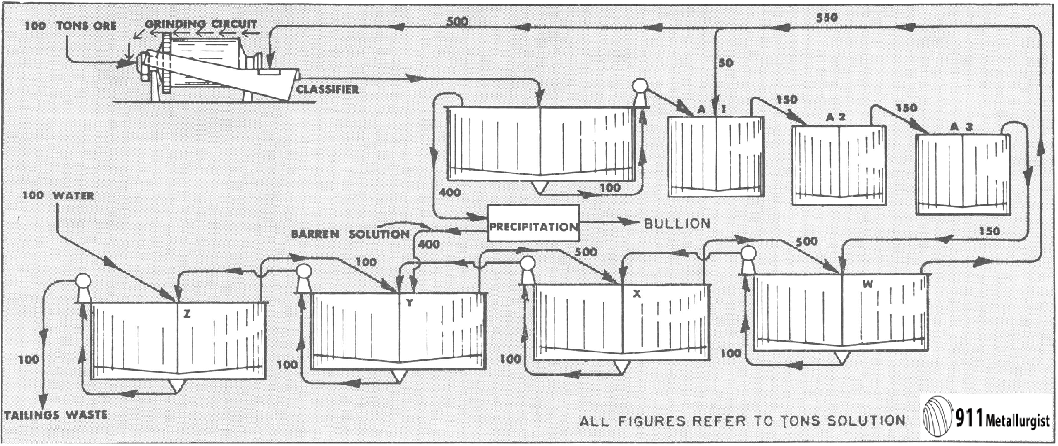
This flow sheet assumes that crushing is done in solution, the overflow from the tank T2 being used for the crushing solution. This crushing solution leaves the grinding circuit with the ground pulp and enters T1, and that part which does not pass to the agitators with the pulp overflows T1 and goes to precipitation. After depositing its gold contents, it is used to dilute the underflow of T3 as it enters T4. The overflow of T5 is also mixed into the feed to T4. The overflow of T4 mixes with the underflow of T2 to form the feed to T3, and so forth, as indicated in the flow sheet. At each succeeding mixture the solution meets a pulp of higher dissolved content than itself and is enriched while the pulp is correspondingly impoverished. The pulp at each step approaches the discharge end of the mill while the solution goes to the feed end—hence countercurrent decantation.
Variables Affecting Decantation Process
The principal variables that may affect the efficiency of the process are:
- Grade of ore.
- Ratio of solution precipitated to ore treated.
- Thickness at which pulp can be discharged.
- Cost of chemicals.
- Rapidity of dissolving, and the place in the circuit where it takes place.
- Efficiency of precipitation.
Since the decantation process is one involving volumes and dilutions, it is possible to calculate accurately what distribution of values should take place under any given set of conditions. As far as possible, each one of the above variables has been mathematically considered independently of the rest and the results have been plotted.
The effect of variations in the grade of ore is shown in Fig. 2 and scarcely needs comment. In practice, of course, no such increase as is shown in the gold-solution curve would ever be allowed to take place on account of the difficulty of precipitating such high-grade solution and the danger of leakage, but the graph shows conclusively that all solutions increase in value in direct proportion to the increase in the grade of the ore and that the higher-grade solutions increase at a much more rapid rate than the final washes.
The important part played by the ratio of solution precipitated to ore milled is shown in Fig. 3. For the particular grade of ore considered, which in this case was $10 recoverable per ton, with precipitation to 3 c., the economic ratio may be roughly determined by inspection of the lowest curve, which represents the value of the solution leaving the last tank of the series with the tailing. It will be noted that the loss in gold increases very fast as the amount of solution precipitated is decreased, while after a certain point the increased recovery due to increasing the volume precipitated is very slight.
The final choice of the exact ratio to be used must be influenced by the cost of precipitation, which is mainly the cost of zinc. To show clearly the effect of precipitation cost on the economic precipitation ratio, Fig. 4 was plotted. I have considered it safe to assume that the cost of increasing the amount precipitated is due to the additional zinc used. The loss in dissolved gold and the cost of the zinc used in precipitation are both plotted to the same scale in cents per ton of ore. By adding the ordinates of these two curves a third is formed which represents the total loss in gold and zinc. The lowest part of this curve represents the economical range and indicates that for a $10 ore, under the conditions assumed with zinc at 26 c., from 200 to 250 tons should be precipitated per 100 tons of ore treated. In dotted lines are shown the corresponding curves for a $5 ore under similar conditions. In this case the range is from 150 to 200 tons. While there is a considerable range within which practically identical results may be expected, it is apparent that each operator should figure out for his own conditions just what his range is.

The next, and one of the most important variables to be considered, is the thickness, or percentage of solids, to which pulp can be settled. In Fig. 5 the values of the various overflows have been plotted so as to show the effect of variations in the moisture in the underflows. The full-line curves represent the values of the solutions—that is, they are shown as per ton of solution—but in calculating losses per ton of ore, the ratio of the solution to the ore present must be considered. The loss in dissolved gold per ton of dry ore for the last tank has, therefore, been plotted in a separate curve, and it is this curve which should be given the most serious attention in determining the suitability of an ore for decantation. The moisture in the pulp also has a direct bearing on the cyanide loss,

which is also shown in Fig. 5. This has been shown in pounds rather than in cents because solution strength and the price of cyanide both affect its value. Enough is shown, however, to make it plain that there is a very decided limit to the density of the pulp that can be handled economically, and one is forcibly reminded that the cyanide strength should be kept as low as possible. Operators as a rule seem to be inclined to “play the game safe” as regards solution strength and it is probable that in many cases cyanide could be saved without any considerable loss in gold by using solutions of a lower strength.
In making the calculations upon which the foregoing curves are based, it was assumed that 75 per cent, of the gold was dissolved in the grinding department and the remaining 25 per cent, in the agitators. This is, of course, an approximation which cannot be accurate, and even with the cleanest ores some gold is dissolved in passing through the tanks following the agitators. This is a condition that has always been met, no matter

what the method of recovering the dissolved value. Changing solution during agitation has been practiced for years in the treatment of silver ores, and in the treatment of concentrates at Goldfield with a view to reducing this lag of dissolving. I have also found that on Goldfield ore, pulp from the final agitators, reagitated without change or addition of solution, would give up no more gold, while reagitated filter tails from the same ore would show a distinct reduction. The same condition exists in the pulp fed to decantation plants and there is little doubt that some dissolving takes place even in the last tanks of the series. Some of this value is lost, particularly that freed near the final discharge but much is recovered that would probably not be won by any other method. The superintendent of one of the decantation plants treating Tonopah ore informed me that his sampling indicated that the additional dissolving taking place in his plant was sufficient to offset his entire dissolved loss and 3 c. per ton additional.

Any considerable dissolving during decantation will be indicated by a difference in the assay value of the solution in the underflow of the tanks as compared with the overflowing solution. In practice there is always more gold per ton in the underflow solution than in the overflow of any given tank, but in the ores of Porcupine district this difference is very small. Other causes may, and no doubt do, tend to produce this difference between the overflow and the underflowing solution. Adsorption is probably the most important and perhaps the least understood of these. In the case of the ores of the Porcupine district this phenomenon is of small importance, as the ore is composed of crystalline schists and quartz and there is little tendency for the ore to flocculate under the influence of the solutions used. The gold and silver ores of the Western States are in many cases in eruptive rocks; these ores usually flocculate in solution and in doing so seem to entrap a portion of the value in the solution. At any rate there is a much more noticeable difference in the assays of tank effluents in the treatment of these ores. Faulty mixing of the products fed to the tank has in some cases been blamed for this. In most plants riffles and other devices are put in launders to insure thoroughness in mixing, but our experience in Porcupine would indicate that the ordinary launder makes a perfect mixture. Adsorption, then, would seem to be the more important cause of these differences, and should be a profitable field for further investigation.
Proper precipitation is essential in decantation, as it has always been in every other process, and, as shown by Fig. 6, dissolved gold is lost in proportion to the amount of value in the barren solution used. It will be observed, however, that the loss does not increase as fast as the value of the barren solution does.
It will be observed that the value of the solution leaving T4 increases at nearly the same rate as the barren solution and that all the preceding overflows increase by exactly the same amount as T4. The water dilution cuts the final loss down to a slower increase than the barren solution itself.
Mechanical Features
Dorr Thickener
The mechanics of the decantation system is of the simplest, but is worthy of study nonetheless. The Dorr thickener is universally used for the separation and is so well known and so standardized that it need only be mentioned in passing. It has been fully described by Mr. Dorr himself in a paper read before the Institute.
The arrangement of the tanks in plan may be largely governed by space available and other local conditions. In elevation it is very convenient to have the last tank the highest and the preceding ones successively lower, so that the overflowing solutions may be transferred by gravity with a minimum of attention. Where such an arrangement is not possible, the tanks may all be placed on the same level using automatically regulated air lifts to transfer the solutions from tank to tank.
Diaphragm Pumps
As a means of transferring pulp, the diaphragm pump has distanced all competitors. The main reasons for this are that it not only pumps but at the same time measures the volume of pulp transferred. The flow of pulp is not easily obstructed by foreign matter, such as chips, waste and

the like, since the openings are full pipe size straight through the pump. The capacity of the pump can be controlled with certainty by means of cone pulleys. The attendant’s duties are all on one floor, as it is operated from the overflow level instead of at the bottom of the tank. Operating cost is very low on a properly designed pump.
Air lifts were used for a time, owing to their cheapness and simplicity, but they are hard to regulate and are wasteful of power. The most careful watching will not prevent them from “running away,” that is, transferring too fast, consequently thinning the pulp and sending large quantities of rich underflow solution toward the discharge. On the other hand, if they are set too slow the gradual thickening of the discharge slows up the flow and finally stops it.
Spigot discharge to a bucket elevator or centrifugal-pump sump has also been tried, pulp and solution being mixed and elevated together. There are several objections to this arrangement, the principal one being high power and maintenance cost for the pumping or elevating machinery. Both the solution and the pulp must be lifted more than the full height of the tank for each decantation. The small high-velocity stream of pulp passing through a spigot at relatively high pressure is subject to frequent stoppages due to foreign matter, and even when this does not cause a complete plugging it interferes with uniformity in operation. There is also the objection that work is done on two floors, one below and one above or near the top of the tanks.
There has been a certain amount of prejudice against diaphragm pumps due to the fact that some of the earlier pumps were poorly designed for the work they had to do. Faulty valves were responsible for much of this. Poor methods of regulation also had their effect.
The practice in most plants in the Porcupine district now is to use cone pulleys for the regulation of capacity, although some of the operators favor regulation by varying the length of stroke.
The valves should be of the floating type, as any hinge device will catch the wood chips that are present in the best-screened pulp. The chips lodged in the hinge of the valve cause leaks which, though small in amount at first, cause cutting of the seat and consequently permanent leakage. With the floating valve there is no place for chips to lodge and the whole circumference of the seat is washed by pulp at every stroke. This type of valve also has the advantage that the lower valve may be placed directly below the upper one and made small enough to be lifted out through the upper-valve seat when the upper valve has been removed. No tools are required for the removal of these valves and it is a simple matter to inspect them.
The best results have been obtained when the working surface of both the valve and seat were of high-grade rubber. Belting was used at first, but it was found that minute leaks were almost sure to start, due to the fact that belting is not yielding enough to close over any chip that may lodge on the valve seat, and that a leak once started would ruin both valve and seat in the course of a few days. On the other hand, valves of rubber seating on rubber have operated 6 months without the slightest decrease in efficiency and with scarcely perceptible wear.
Diaphragm pumps have been operated at speeds varying from 15 to 100, the higher speeds usually in conjunction with a short stroke.
The practice at the Hollinger mill has been to use a low speed and a stroke as long as the diaphragm could safely stand. Measurements taken on the Hollinger pumps equipped with standard No. 4 Gould diaphragm at 3-in. stroke gave results as shown in the following table:

From the above figures, which are typical of numbers of tests made, it may be inferred that the volume pumped is roughly proportional to the speed of the pump but that leakage is slightly greater on the lower speeds.
The low speeds and the placing of the discharge lips high enough above the discharge valve to leave 3 or 4 in. of pulp over the valve at the end of the upstroke have rendered the pumps of the Porcupine district practically free from the splash and dirt that have been one of the chief objections to diaphragm, pumps in the past.
Where tanks have a settling capacity of over 125 tons of solids per day, it may be found advisable to use two diaphragms in parallel, making a duplex or even a triplex pump. This arrangement has several advantages; with the lowered speed, strains of the pump are lessened and distributed, and repairs can be made on one unit without complete stoppage of the tank discharge. Diaphragm life appears to be roughly proportioned to the number of strokes, so that an increase in the number of diaphragms employed, with a corresponding decrease in the strokes per diaphragm does not result in an increased cost for diaphragms.
As a safeguard against waste and other foreign matter it is advisable to screen the pulp before it goes to the decantation tanks, and where small wood chips are to be expected a fairly fine screen, usually of punched plate, will be of great service in protecting thickeners and pumps.
Measurement of Solution Precipitated
Every cyanide plant has some method of determining the amount of solution precipitated, and in decantation plants having only one series of tanks the entire tonnage of precipitated solution is used at one place. If, however, more than one series of tanks is used it becomes important to split this precipitated solution into parts proportional to the tonnage of ore being washed in each series. This can not be done by regulating the valve, at the outlet of the barren line, as trial has shown that under some conditions an increase of as much as 50 per cent, can be made in the amount flowing from a pipe line without any visible change in the stream.
This difficulty has been overcome by the use of V-notch weir boxes, one for each series of tanks. In each weir box is a float compartment and a float operating an indicator on a scale which reads in tons per 24 hr. While the weir box, which can be readily made at any mine, is not a recording instrument but gives only an instantaneous rate reading, its use greatly simplifies the problem of proper distribution of barren solution. Water also should be added in proper amounts and uniformly distributed. A smaller weir box has been found convenient for this purpose.
It is usual to determine the specific gravities of various pump discharges about a decantation plant at least once a shift. In a small plant this consumes little time but if there is a large number of measurements to be made the distance to be covered by the operator is considerable, especially if he has to return to a central point for each weighing. In such plants, a spring balance with a dial and revolving hand, that can be carried about the plant, is a good type. I have used a milk scale having an adjustable tare-indicating hand, which makes one complete revolution for 10 lb. I use a narrow-necked can which holds just 10 lb. of water when level full. This makes it possible to add a paper dial which can easily be divided so as to read directly specific gravities. The large sample makes possible accurate readings and enables the operator to determine gravity at the place where the sample is taken.
Tray Thickeners
In his paper on the Dorr metallurgical apparatus, Mr. Dorr touched on the future of tray thickeners, and spoke of the possibility of a complete decantation plant being installed in one tank. While this has not been done as yet, a four-step decantation followed by a continuous filter is in operation, the four steps of the decantation being completed in two tanks equipped with single trays. While no figures have been made public the results are said to be creditable.
Another use of the tray in decantation, which is shortly to be tried at the Hollinger mill, is to increase the capacity of existing plant without increasing the number of tanks installed. Since the same grade of solution is handled in both tank and tray there is no danger of any mixing of solutions of different grades. This plan should decrease the cost of buildings, tank foundations and building site in almost direct proportion to the increase in capacity gained, while tank cost, power and labor should all be decreased to a marked degree. The outcome of this experiment should have a direct bearing on the future of the decantation process. It must, however, be borne in mind in this connection that some slimes require time for their final thickening and consequently necessitate a tank of some depth, while other slimes find their capacity limit in the thin-pulp settling rate. For this latter class, as explained by Messrs. Coe and Clevenger in their paper on slime settling, a shallow tank or tray is sufficient while the former class requires a tank of carefully calculated depth to give the required time for thickening.
Decantation Plant
The Hollinger decantation plant consists at present of five rows of 40-ft. tanks, four tanks to a row, forming a plant of five units. The tanks are arranged with a difference in elevation of 2 ft. 6 in. between steps with the final tanks of the series the highest, so that all solutions gravitate through and out of the plant to precipitation. The Barrett specification roof is supported on flat trusses, the lower chords of which pass just above the tank rims. These trusses also serve to support the thickener mechanisms and the walks between the tanks.
The diaphragm pumps used were designed by the company’s staff, and have been very reliable and economical. They are all three-throw or triplex pumps so that in spite of the large tonnage handled the duty on each diaphragm is light. It is not uncommon for diaphragms to last 300 days while the life of the present type of valves and seats has yet to be determined.
The pumps are used not only for pulp transferral, but also for the final discharge. This makes regulation of the final discharge for moisture much easier, more reliable, keeps the work of the operator all on the upper floor and allows the tailing to be discharged at a considerably greater elevation than would otherwise be the case.
The barren solution and water wash added to each row are measured by separate float-reading weir boxes assuring uniform results from the various units.
Labor
The plant is operated by one man per shift who oils all machinery, watches and adjusts the pumps and records their performance. The solution man makes titrations and regulates the addition of water solution but has no other duties in the decantation plant. A repair man on day shift makes all repairs and has time for other work.
Power
The power for each tank including motor and line-shaft losses is under 1 hp., while each three-throw pump consumes about the same amount.
Cost
The costs for the 12 weeks from Jan. 28 to Apr. 21, 1916, have been taken as typical of what is done by this plant at its present capacity. During this time 85,854 tons were decanted at a cost of $599 for supplies, including power, and $1,194 for labor, or $0.007 per ton for power and supplies, and $0.0139 for labor, making a total of $0.0209 per ton for decantation. Labor is no doubt higher here than it will be in the future, as a greatly increased tonnage is to be treated while supplies and power should remain nearly the same. The cost as it stands is about 40 per cent, of the cost of filtering on leaf filters at about the same daily tonnage.
Extraction and Recovery
In the ores of the Porcupine district the recovery by dilution seems to be almost the theoretical maximum. Adsorption does not seem to have any appreciable effect. There is a slight dissolving during decantation which, while it adds to the recovery, makes the soluble loss somewhat greater than it would otherwise be.
The figures quoted below on chemical consumption and recovery refer to only two units of the Hollinger plant. The figures on these units are given because the other units of the mill share their feed with the original Moore filter plant, and likewise their barren solution, while for commercial reasons the two units in question have been given a separate solution system and separate precipitation presses. These two units are therefore the only ones upon which all the figures are available.
In comparing the results quoted, however, it should be borne in mind that the flow sheet has been modified in this plant somewhat, because of limitations of space, so that the overflow of T2 instead of that of T1 goes to precipitation. The effect of this is to raise the theoretical value of the overflow of the last tank 3 c. at 3 to 1 precipitation.
A statement of results follows:
Period covered, same as that for which costs were given—from Jan. 28, 1916, to Apr. 21, 1916.
Tons of ore treated………………………………………………………………………38,885
Value per ton of ore treated…………………………………………………………..$8.92
Ratio of ore to solution precipitated…………………………………………….100 to 285
Tons solution precipitated……………………………………………………………….110,604
Strength of cyanide used………………………………………0.9 lb. per ton, or 0.0045 per cent.
Cyanide added per ton of ore…………………………………………………………..0.46 lb.
Difference between pulp feed and pulp discharge for first tank after agitators……25 c.
Average moisture in tails…………………………………………………………45 per cent.
Average value of barren solution……………………………………………………..3.2 c.
Dissolved gold per ton of solution discharged…………………………………..11.71 c.
Dissolved gold per ton of ore discharged…………………………………………..9.57 c.
It is theoretically possible, taking into consideration the flow sheet, the grade of ore treated, the barren solution used and the thickness of pulp attained, to have reduced the overflow of the last tank to 7.6 c. leaving a difference of 4.1 c. to be accounted for by continued dissolving, adsorption, etc.
Viewed in one way it may be said that actual losses are 54 per cent, higher than theoretical, but where one is dealing with samples so easily affected by faulty manipulation and where any error except losses in assaying tends to raise the results, a check to 4 c. does not seem bad. The average loss would have been somewhat less if the occasional high results had been omitted, but this was not done.
From the foregoing, I believe one is warranted in concluding that a reasonably accurate forecast can be made of the results to be expected from a decantation plant and that these results may compare very favorably with the results obtained from filter plants.
In conclusion I would say that I am indebted to P. A. Robbins, Managing Director of the Hollinger company, for permission to quote results from the Hollinger plant.
Discussion
J. V. N. Dorr, New York, N. Y.—I have read Mr. Eames’ excellent paper on this subject with great interest, for besides being connected with the design and installation of the first modern countercurrent decantation plant, he was associated with me in the development of the thickener in the Black Hills some years earlier, and has now been operating the largest plant that has used this method of treatment. His discussion of the influence of different factors on the results obtained is quite thorough, but several features I think may not be apparent to the reader who has not studied the subject carefully.
Grade of Ore That Can Be Treated
Mr. Eames has shown graphically that the assay of all solutions increases directly as the grade of the ore treated. He has not emphasized, however, the fact that, as most operators prefer to keep the assay of pregnant solutions down below a certain figure in order to insure complete precipitation, an increase in ore value beyond a certain point means a proportional increase in solution precipitated and therefore not only an increase in the percentage of dissolved gold recovered, but an actual decrease in tailing loss.
The importance of the influence of the percentage of moisture in the underflow on loss is made clear, and I may add that unless it is quite evident that pulp can be safely settled to 50 per cent, solids, or more, it is usually advisable to use a continuous filter at the end of a decantation plant to reduce losses in cyanide and gold.
Dissolution in Thickeners
The influence of a change of solution on silver dissolution has long been emphasized and most gold operators have recognized the annoying way in which a gold ore after being agitated until nothing more can be dissolved will loosen up again when almost ready for the dump after the dissolved metal has been removed by decantation or filtration. Continuous decantation gives favorable conditions for this additional dissolution and a chance to recover most of what is thus dissolved. This is especially true if an extra tank is used in the series and barren solution added at the second tank from the end instead of the first, as shown in Mr. Eames’ Fig. 1.
It can be calculated that the use of this tank will reduce the mechanical loss of cyanide by one-third and cut the gold loss as well; but the saving in gold or silver that may dissolve when the pulp is first diluted with weak solution may be as important.
At one plant in the Southwest, where one of the agitators was not in use as additional dissolution would not pay the cost of its operation, the company found that 30 c. more was being dissolved in the decantation thickeners.
It has been pointed out that decantation alone should only be applied to suitable ores, but it is becoming well recognized that when filters are used one or more steps of countercurrent decantation should precede them, as the additional dissolution will more than pay operating expenses; also, the lower-grade solution going to the filter means lower filter costs and tailing losses.
The added cost of operating an additional thickener on the average ore is so low as to be difficult to estimate and may safely be placed at less than 1 c. per ton, including reasonable amortization.
Trays.—Mr. Eames has referred to the use of trays in decantation plants. I may say that one self-supporting tray giving double capacity has been in operation for some time in a 50-ft. tank and one for a 75-ft. tank has been designed.
Tanks with several trays are also in operation, so that the problem, especially apparent in cold climates, of large mill buildings for a decantation plant, is being rapidly solved.
Counter Current Washing and Leaching Calculations
Many processes in the hydrometallurgical and chemical industries require the separation of dissolved material from suspended solids. Counter current decantation (CCD) with thickeners is one of the methods generally used. The process engineer needs a quick and accurate CCD calculation method. Several theoretical CCD calculation methods are available in the literature .
The unit of the following defined letters is a rate. It may be tons per day, pounds per hour, dollars per day, etc. (one at a time).
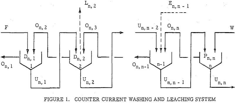
F = Solute in Feed solution.
W = Solute in Wash water.
Un, i = Solute in Underflow solutions accompanying solids (solubles in underflow liquid).
On, i = Solute in Overflow solutions.
En, i = Solute in streams (solutions) Entering thickener i.
Ln, i = Solute in streams Leaving thickener i.
Dn, i = Soluble materials Dissolving or leaching from solids into solution thickener i.
Pn, i = Solute precipitating or absorbing from solution on to solids.
Mn, i = En i – Ln i + Dn i – Pn i, a summation as defined being constant in derivation, except
Mn, n = W + En, n – Ln, n + Dn, n – P n, n
1, 2, i, n indicate numbers of thickeners (or other separator such as filters cyclones, centrifuges, etc.) starting with 1 for the thickener where feed is first added. The sub-script i cannot be zero or larger than n. The first sub-script indicates total numbers of stages, and the second subscript indicates the number of stage.
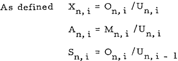
An i = Mn i/Un i, a ratio as defined.
B = W/Un n, a ratio as defined.
Cn i = Mn i/F, a constant as defined.
Xn, i = On i/Un i, a ratio as defined.
Rn, i = On i /Un, i – 1 where all of Mn i are equal to zero and Rn i is equal to washing efficiency in decimal expression.
Sn i = On i/Un i-1 where Mn i is not equal to zero and Sn, l is not equal to washing efficiency.
RT = Sn l/(l +∑i n= l Cn, i washing or leaching efficiency in decimal expression.

The general form of equations of Set (1) for any stage i, is
![]()
Let Mn, i = En, i – Ln, i + Dn, i – Pn, i· Mn i is a constant because En i, Ln i, Dn i and Pn i are constants. Then, equation (A) will be simplified to
Un, i – l + On, i + l + Mn, i = On, i + Un, i……………………………………………….(B)
Thus the ratio of solute in overflow of thickener i to the solute in the underflow of previous thickener i – l is

Equations are converted to four other forms of equations, (D), (E), (F), and (G)
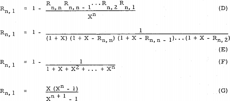
Compare equation (D) with Perry’s equation, R = l – (D/F – D)n (= l – l/Xn), or equation (E) with other equation, R’ = l – (D/F)n (= l – l/(l + X)n ).
Example:
Using equations of Set (3) to solve Perry’s example will be as simple as
Let X3 3 = 3, X3, 2=3, and X3 l = 2. 1
Then R3, 3 ¾
![]()
![]()
Equation (F) is the same as Woody’s equation in his first case.

When dissolution (leaching) or precipitation occurs in the system, or When the streams carry the solute being added in or withdrawn from the system.
Countercurrenl Recantation with thickeners, or C.C.D. as it is generally known, is, of course, only one way of separating dissolved material from undissolved. Other unit operations such as Countercurrent Filtration (C.C.F.) and Countercurrent Classification (C.C.C.) are widely used. The same principle s may also be applied to centrifugally assisted decantation, as with nozzle or solid bowl type centrifugals, and to separations using screeds, either gravity or centrifugal type. Another form of countercurrent washing applicable to granular materials is practiced in continuous ion exchange operations.
.
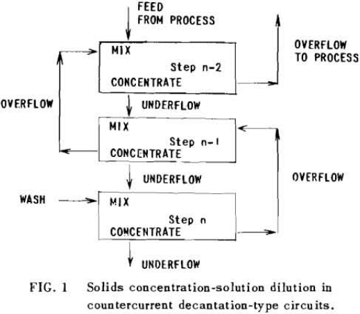
The second principle used in washing solubles from solids is that of solids concentration-solution displacement. Here the solids are restrained from movement while wash solution is forced through the interstices in a countercurrent fashion.
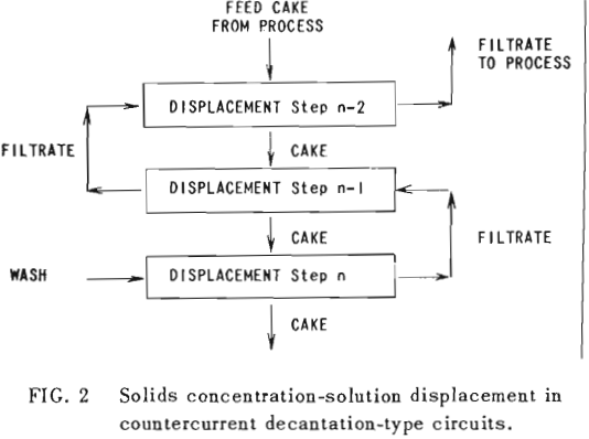
It is thus seen that the basic difference between the two principles involved is in how the wash is applied. In the one case the washes merely serve to dilute the liquors contained in the voids from one step to the next, while in the other case the void liquors are actually displaced by the wash solutions in a more or less plug flow fashion. If the displacement were 100% perfect plug flow, one void volume of pure solvent wash would displace 100% of the original liquor contained in the voids and there would be no need for a countercurrent operation. The washing would be complete in one washing step. What is more, all of the wash water applied would go out in the final cake so that there would be no dilution of the filtrate. Actually the displacement is never 100% plug flow but may apparently be as low as 35% or as high as 90%.
All solution weights will be presented on the basis of tons per ton of solids involved. Thus all thickener underflows and filter cakes will be on a so-called “dilution” basis. Wash water applied, overflows, filtrates and the like will be handled similarly. Thus, per ton of solids being washed, there will be F tons of liquor entering the washing circuit with the solids, and U tons of solution leaving the circuit with the washed solids; while W tons of wash water will have been applied and K tons of weak liquor recover¬ed as overflow or wash filtrate. Fundamentally, by materials balance,
W + F = U + K……………………………………………………….(1)
If the dilution of the entering feed is the same as that of the exiting solids; i.e., U = F; then W = K.
U, F, K and W without subscript will be used to represent the overall figures for the circuit as a whole. They may be also employed with subscript to represent the corresponding terms for any state of the washing circuit.
An extremely important point to keep in mind in all washing calculations and comparisons is the “net wash advance,” A, where
A = W – U = K – F…………………………………………………..(2)
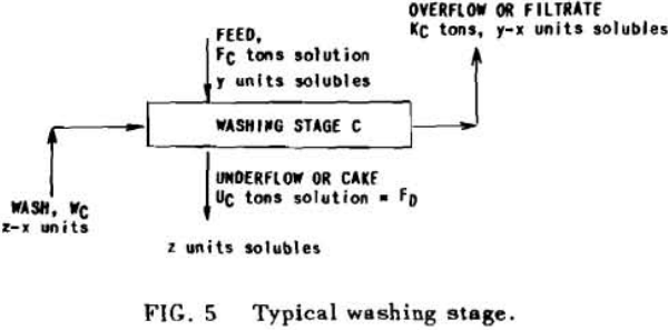
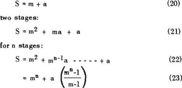
Application to Solution Dilution
A fundamental tenet of solution dilution operations is that, in any stage, the concentration of solubles in the overflow and underflow solutions is the same. Therefore the weight of solubles going each way is proportional to the volumes or weights of these solutions.
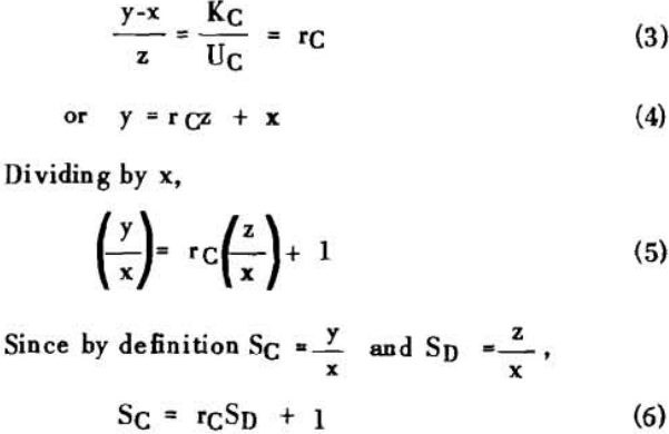
S = r + 1……………………………………………………….(7)
for two stages
S = r² + r + 1…………………………………………………..(8)
for n stages

S = rn (rn – 1) (rn – 2) + (rn – 1) (rn – 2) + (rn – 2) + 1……………………………………(11)
Application to Solution Displacement
The solution filling the voids in a washed filter cake can be considered to be made up to two portions: a certain fraction, R, of solution as present before the wash was applied; and the remainder, 1-R, of the composition of the wash which was applied.
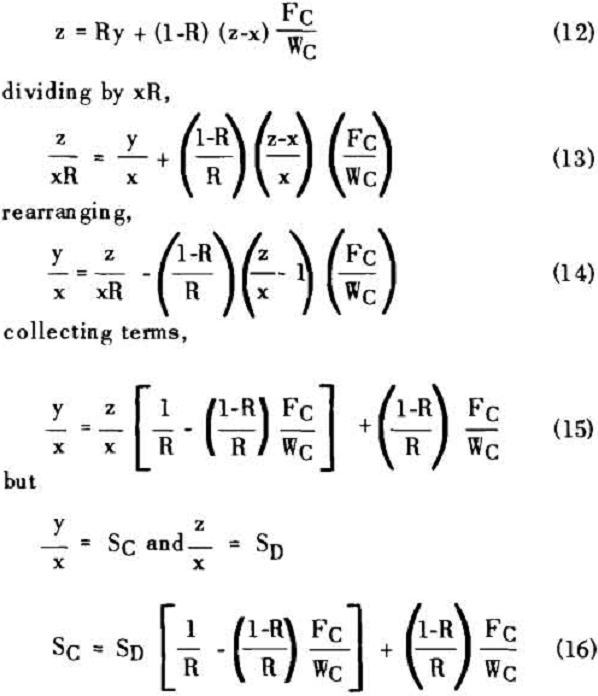
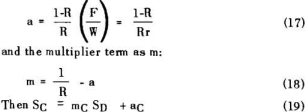

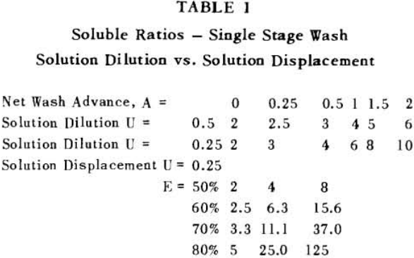
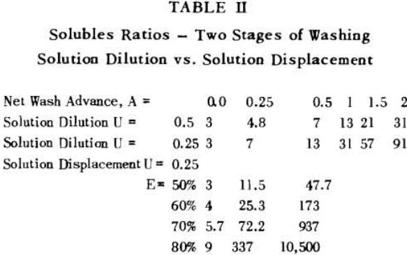
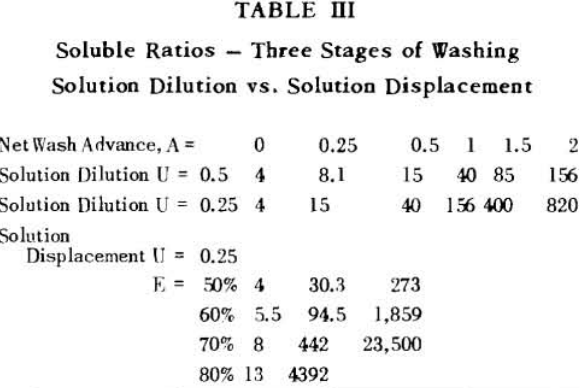
Soluble ratios have been calculated to compare the two principles for different net wash advances with one, two and three stages of washing. For a single washing step, lists the solubles ratios for solution dilution with thickeners at an assumed underflow % solids of 66.7; solution dilution for filtration with
