SETUP INSTRUCTIONS
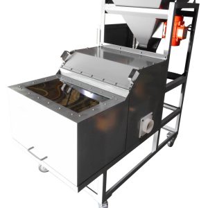
Before you can begin splitting, it is important that the machine is properly setup for the material you plan on processing. Every material has unique properties so it is recommended to run several test samples using different settings to determine the optimal configuration for your material. Use the steps below as a guide to set up your machine.
Read all of the steps before proceeding with any tests. Some features need to be set up and adjusted at the same time.
1.) Hopper adjustment:
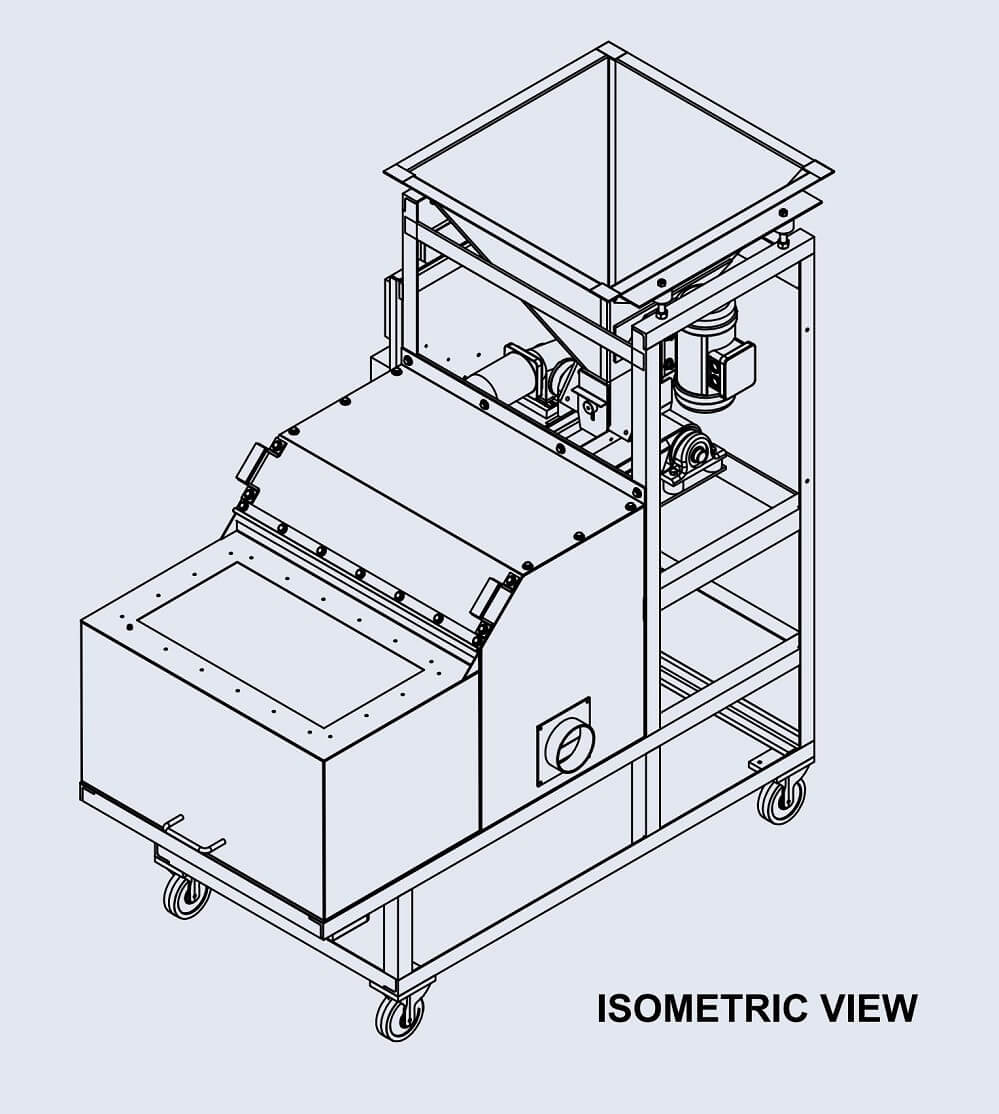
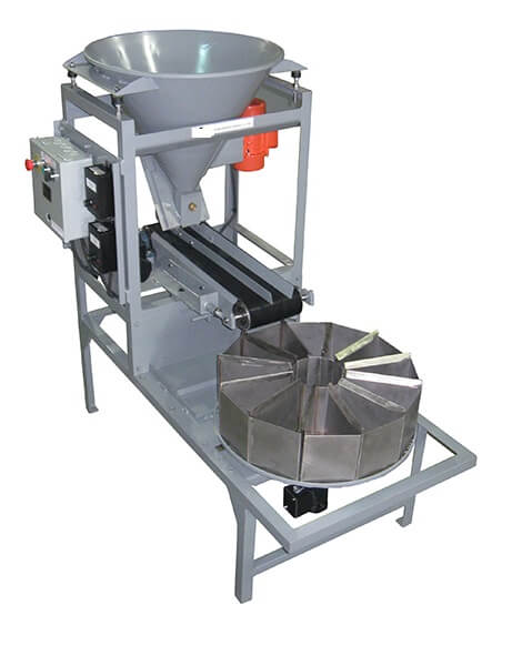
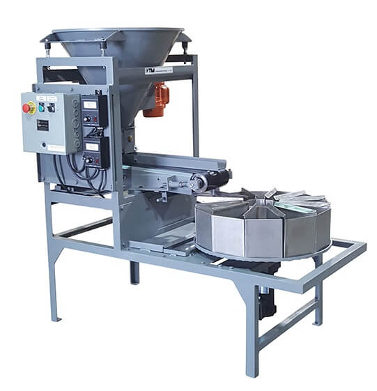
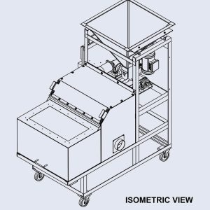
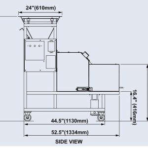
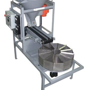
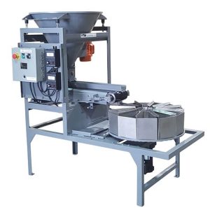
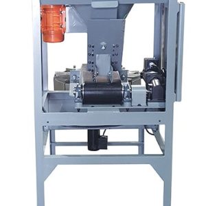
The height of the complete hopper/gate assembly can be raised or lowered to change the clearance where material falls on to the belt. Rotate the 4 adjustment screws (RS007) that hold it up on the top, making sure that they are all adjusted equally. For most materials it is recommended to leave the hopper at the factory preset height. Flow adjustment is achieved through the gate.
2.) Gate adjustment:
There are 2 sections of the gate that can be adjusted to regulate material flow. The main gate on the back can be set anywhere from all the way closed to fully opened. For very fine materials it is typical to have the gate set with less opening. Make sure that when splitting coarse materials the gate is set with enough opening for the largest particles to easily pass through. Experiment with different opening settings while running a test sample to find the optimal position for your material. Once satisfied with the opening setting, use the small knurled pin to mark the stop position on the series of holes on the gate.
The second adjustable feature is a small plate (RS005H) on the front side. Loosen the brass adjustment knob (RS005J) to slide this plate up and down. This plate should only be adjusted to skim the height of material as it flows out from beneath the hopper. Do not use it to restrict or cut off material flow completely, as it will cause wear on the belt.
3.) Carousel adjustment:
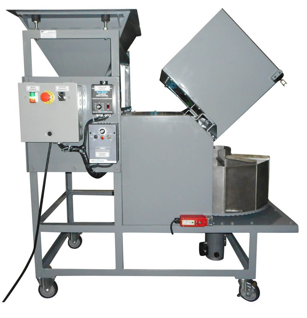
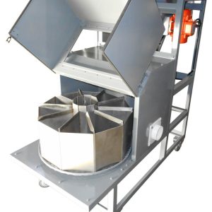
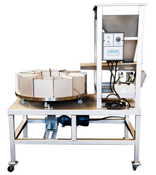
Turn the carousel on and use the dial on the control panel to adjust the carousel rotating speed while minimizing dust and particles flying out as material falls into the containers. Use good judgment to establish a suitable speed as you observe the way material falls.
4.) Conveyor Belt:
Before turning on the conveyor belt, fill the hopper with test material. Make sure that the gate is all the way closed before pouring material in.
With the carousel rotating, turn the conveyor belt on and open the gate. You should begin to see material moving from beneath the hopper on to the belt. The conveyor also has a variable speed control to adjust the speed at which material flows. Turn the dial to a point where you are satisfied with the rate of flow. You will want to adjust the gate opening settings at the same time.
5.) Hopper Vibrator: (optional)
Some machines are supplied with a vibrator on the hopper to prevent clogging at the output and sticking of material to the inside. This is not adjustable, simply turn it on or off and take note of the effect it has on the way material flows. Not all materials requires that the hopper vibrator be turned on.
OPERATING INSTRUCTIONS:
In order to safely achieve accurate and repeatable results, it is critical that you follow the operating procedure below. Refer to the setup instructions on page 3 before you begin running samples.
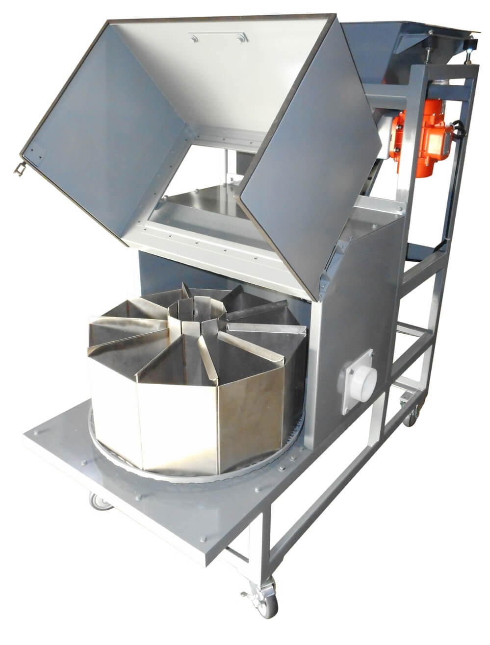
- Place all of the collection containers on the carousel tray and ensure that they are seated properly within the carousel edge. For machines supplied with reject collection capability, make sure the containers are properly hooked on the rotating carousel in the center.
- Pour material into the hopper. Make sure that the gate is closed all the way.
- Turn on the hopper vibrator (optional) if needed.
- Turn on the carousel motor and adjust to the desired speed.
- Turn on the conveyor belt and adjust it to the desired speed
- Open the gate to the preset position.
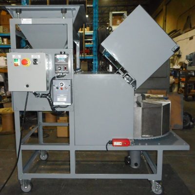
- Close the lid. (Optional)
- Let the machine run until all material has been collected within the containers.
Note: It is imperative that the carousel motor dial, conveyor belt dial, and hopper vibrator switch are not touched while splitting occurs, as this will cause inaccurate results.
DUST EXTRACTION (WITH OPTIONAL ENCLOSURE ONLY)
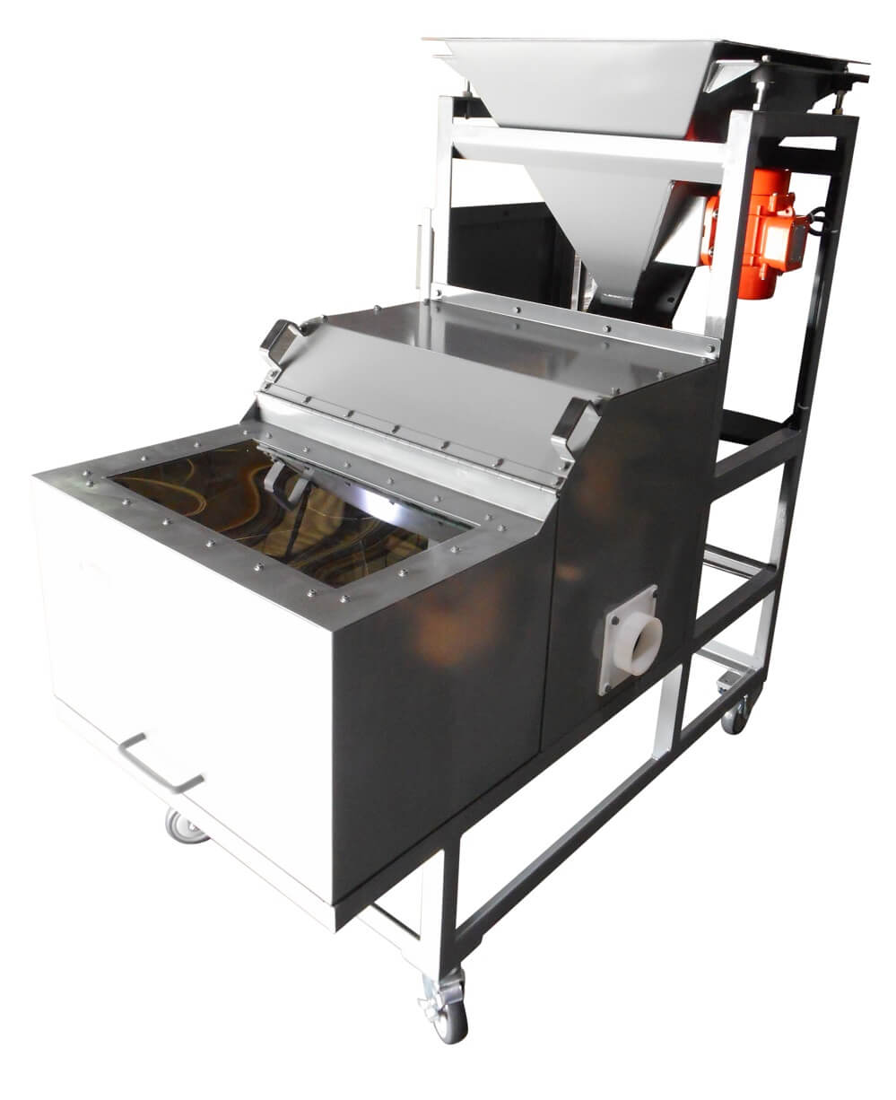
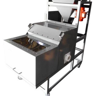
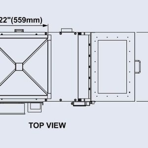
Units with an environmental enclosure are equipped with a 4″ diameter port on the side to use if your operation requires dust extraction. When hooking up your dust extraction system, it is recommended to have an air regulating (Butterfly) valve installed to optimize air flow. If dust extraction is not required, a cover plate has been supplied. Unscrew the duct outlet and screw the cover plate on in its place to block the hole.
INTERLOCK SAFETY SWITCH (OPTIONAL)
Some machines are equipped with the optional interlock safety switch. This is designed to prevent the lid from opening when the machine is in operation. When the machine is powered on, and not operating, the lid can be opened and closed as needed. If there is no power to the machine the lid will remain locked. Should the lid need to be opened when the machine is not powered on, use a phillips screwdriver as shown below.


