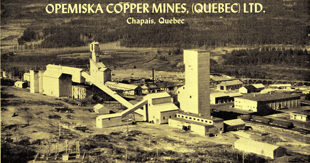
Aerial view of the Opemiska Copper Mines (Quebec) Ltd., Mill Buildings and Shaft Area.
Introduction
The Opemiska mine property is in Levy Township in Chibougamau area of Quebec and is comprised of 487 acres of patented claims contiguous with 2,215 acres held under development license. The townsite of Chapais which serves the mine community is complete with all the necessary services including housing, schools, churches, hospital, recreation center and stores. Direct railway service is provided by the Canadian National Railways to Western Quebec and the Lac St. Jean district. There is a highway connection via Chibougamau, a distance of 160 miles to St. Felicien near Lac St. Jean. Telephone, telegraph and scheduled air services are available.
The mine shafts, milling plants and other facilities on the property are strategically located on the northern slope of a large rock outcropping. Lying below and to the northwest is the tailings disposal area while on the opposite side of the outcropping, extending to the southeast, is the townsite of Chapais.
The original mill at Opemiska began production on December 8, 1953, at a rate of 400 tons per day. Operations were centered around the Springer No. 1 shaft. In 1955 this capacity was increased to 800 tons per day by doubling the mill equipment and wood frame mill building, excluding the crushing plant.
Following successful mine development in 1956 it was decided to increase milling capacity to 2,000 tons per day. This expansion took place in two stages, the first to a 1,200-ton daily rate completed in April, 1958, the capacity of the existing mine shaft and crusher plant. The final stage of the expansion to the 2,000 t.p.d. rate was completed in November, 1959. To accomplish this the Springer No. 2 production shaft was sunk to a depth of 2,414 feet, a new 250-ton per hour crushing plant was installed, conveyors and a 4,000-ton catenary fine-ore storage bin were built. The construction of the latter facilities was of steel and laminated asbestos while the extension to the mill building proper was of wood-frame construction.
The current milling rate is 2,050 dry tons per day or an average of 62,000 tons per month. This rate cannot be appreciably increased without reducing concentrate grade or recovery. However, provision has been made for the easy installation of specific items of equipment to increase capacity, dependent on further mine development. For example, one end of the steel catenary bin is of segmented construction to facilitate its removal for extension of the bin at minimum cost. The layout can be added to and, with the original 100 ton-per-hour crushing plant and conveyors being maintained in stand-by condition, it is also possible to sectionalize the mill without major change.
History
The property was staked in 1929 by Leo Springer on behalf of Prospectors Airways. The dark rock outcropping, upon which the milling plant and the other facilities are situated, had been exposed to view from the air by a recent forest fire. Following the preliminary surface exploration, Ventures Limited, one of the participants in Prospectors Airways, undertook the financing and further development of the property. Considerable trenching and some 6,700 feet of diamond drilling were completed and in 1936 underground development commenced. A shaft was sunk to a depth of 547 feet and over 5,000 feet of lateral work was done on three levels. Operations were suspended in 1937, at which time ore reserves were estimated at 283,000 tons in the No. 1 and No. 2 zones, averaging 7.4% copper and 0.13 ounces of gold per ton.
In 1951 the company was refinanced and the following year the mine was reopened. During rehabilitation of the old buildings, installation of a new mining plant, and dewatering of the underground workings, some 22,000 feet of surface diamond drilling was done. This drilling resulted in the discovery of the No. 3 ore zone, the most important ore structure yet found on the property. Following test work by Lakefield Research Limited, the first 400-ton per day concentrator, designed by Mr. William Dunn of the Ventures staff, was installed in 1953.
Geology and Mineralization
The property is underlain by a strongly folded, differentiated, basic sill complex cut by numerous faults related to a major regional thrust. The ore bodies currently being mined are confined to fractures in the upper portion of the sill known as the “Ventures” gabbro. Mineralization, consisting of chalcopyrite, pyrite and magnetite occurs in east-west shears with a northerly dip and easterly plunge.
As of December 31, 1960, the ore reserves were estimated as follows:
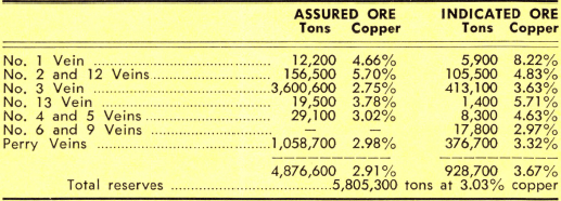
The future holds promise for the eastward extension of the Springer zones and for finding new ore-bearing structures such as those now being developed at the Perry mine.
Mining
The original shaft designated the Springer No. 1, has been deepened to 2,232 feet with levels established 150 to 175-foot intervals. This shaft is adjacent to the original 100 tons per hour crushing plant and constituted the only mine opening up to and including the 1,200- ton per day mining rate.
A new 3-compartment production shaft, designated as Springer No. 2, located 750 feet east of Springer No. 1 shaft, was sunk to a depth of 2,414 feet. Levels were established and connections made with Springer No. 1 on the 525-foot, 975-foot, 2,000-foot and 2,150- foot horizons. A 36″ x 48″ jaw crusher was installed at the 2150-foot level. A four-rope Westinghouse (Koepe type) friction hoist is installed in this shaft, giving push-button ore hoisting to the head frame bin which feeds the new 250-ton per hour crushing plant at the shaft-head.
A third shaft has been sunk to a depth of 2,020 feet at the Perry mine, about 2,900 feet east of the Springer No. 1. Levels correspond with those at the Springer No. 1 and connections between the Springer and Perry mines have been established on the 975-foot and 2,000-foot levels. This section of the mine is now under development and the ore will be trammed to the underground crusher on the 2,150-foot level.
Three different stoping methods are employed in the Springer mine. Shrinkage stoping is generally used in narrow veins. The wide section at the west end of No. 3 vein has been developed for long blast – hole sublevel stoping. In the central section of the No. 3 vein, where the ore width varies between 10 feet and 50 feet, stoping is done by the cut-and-fill method. Mill tailings are being used for back filling.
Milling
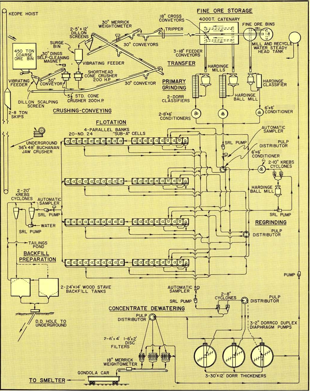
INTRODUCTION — Primary crushing underground of mine-run ore produces a minus 5-inch product which is hoisted to the surface for two further stages of crushing. The secondary and tertiary crushing stages with closed circuit screening give a minus 5/16″ product. Bin storage of fine ore is provided ahead of three parallel single-stage grinding circuits. Mechanical classifiers close the circuit with primary grinding mills. Classifier overflows are conditioned, mixed and distributed as feed to four parallel banks of No. 24 (43″ x 43″) “Sub-A” Flotation Cells which rough, scavenge and two-stage clean the concentrates. Finished concentrates are also produced from rougher cells. The scavenger concentrates and cleaner tailings pass to a regrind ball mill operating in closed circuit with a cyclone classifier, before being returned to the flotation feed. Cyclone and thickener dewatering of the concentrates precedes filtration and loading of the product in railway cars. The flotation tailings are either pumped to the disposal area as such or are two-stage cycloned for recovery of sand for mine backfill.
Crushing, Screening, Conveying and Storage of Fine Ore
The primary crusher, located on the 2,150-foot level of the mine, is a 36″ x 48″ Birdsboro-Buchanan jaw crusher. The minus 5-inch product is hoisted in the Springer No. 2 shaft to a 500-ton steel head-frame bin. Bottom feeding of the bin into the surface crushing plant is provided by chute and 30″ x 72″ Jeffery vibrating feeder.
Coarse ore from the feeder passes over a 4′ x 6′ Dillon screen fitted with a single ¾” by 4″ screen cloth. This screen distributes the coarser ore to the secondary 5½ -foot Symons standard cone crusher and the finer ore to the secondary screens before the tertiary 5½-foot Symons short-head cone crusher. A 30-inch Dings self-cleaning magnet located at the head of the feed belt protects the standard cone crusher from tramp steel.
Ore from the standard cone crusher joins the undersize product from the primary screen and is conveyed under a 24″ stationary magnet to the secondary screens consisting of two parallel 5′ x 12′ double-deck Dillon vibrating screens. These screens are fitted with a 5/16″ by 4″ S-slotted lower-deck cloth and the oversize is retained in closed circuit and fed by a 36″ x 48″ Syntron vibrating feeder to the tertiary 5½-foot short- head cone crusher. The undersize is conveyed to the fine ore storage bins.
The double-deck screens are enclosed and all crushing equipment, loading and transfer points are shielded and ventilated. A No. 18 Model 1260 Wheelabrator dust collector is connected to the ventilating system capable of exhausting 12,600 C.F.M. which keeps the dust count well below the limits set by the mining regulations.
Conveyor galleries are steel structures with laminated asbestos siding and wood decking. The mechanical equipment was supplied by Stephens-Adamson. The carrier belts are all 30 inches wide and are operated at belt speeds of 200 feet per minute. Their maximum slope is 15 degrees. Fine ore is conveyed over a Merrick type S.V. weightometer to storage which consists of one 4,000-ton steel catenary bin and two 600-ton wood-stave bins.
The crushing plant is capable of supplying the weekly mill tonnage on a 5-day basis but at present is being operated two shifts, 12 to 13 hours crushing time per day, six days a week. So far, on the Symons crusher, mantle life has averaged 240,000 tons and bowl liners 300,000 tons of ore for an average cost of 2.3 cents per ton milled. With the primary crusher station at the 2,150-foot level and mining currently being mainly confined to the upper horizons, the long drop through the ore passes produces an abnormally high content of fines in the feed to the crushing plant. These fines thus retain a relatively high proportion of moisture which necessitates positive screening ahead of the Symons crushers, not only to distribute the load but also to protect the crushers from excessively wet fines. For the same reason single decks are presently used on the secondary screens. On the latter screens cloth life is 7 to 9 weeks and circulating load over them amounts to 50 percent.
Grinding and Classification
Collecting conveyors supply 2,000 t.p.d. of ore to the feed belts of three independent primary grinding circuits. The No. 2 grinding circuit comprises a 8′ x 72″ Hardinge conical ball mill in closed circuit with a 6′ x 14′ Hardinge counter-current classifier. This mill has a 48″ drum, 54″ radius combination scoop feeder and is driven at 21.3 r.p.m. by a 17-tooth pinion and a 55 Dominion Engineering coupling direct-connected to a 250 H.P., 360 r.p.m., 550-volt wound rotor motor.
The No. 3 and No. 4 grinding circuits are identical, consisting of Hardinge 11′ – 3′ – 6′ – 10′ Tricone ball mills in closed circuit with 8′ x 32′ Dorr HX classifiers. Each of the Tricone mills has a combination 60″ drum and 72″ scoop feeder and is driven at 18.1 r.p.m. by a 26-tooth pinion through a 7¼-S Hamilgear coupling and a 280 – CS Hamilgear single reduction speed reducer connected to a 600 H.P., 1,200 r.p.m., 2,200- volt wound rotor motor.
All mills are high pulp level reverse cone grate type and have spiral discharge trommels. Ball mill liners are Ni-hard double-wave type. Grinding media is 2½” and 3″ balls. Opemiska ore has a specific gravity of 2.9 and grinding in the ball mills is done at 78% solids. The approximate split of the feed is 350, 850 and 850 tons per day between the Nos. 2, 3 and 4 milling circuits.
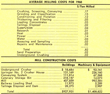
Ball and liner consumption and scoop repairs have been moderate. The average grinding ball consumption during 1960 was 0.99 lbs. per ton milled. Liners in the No. 2 grinding mill have been partially changed twice amounting to a consumption of 48,400 lbs. of liners for 409,754 tons milled. This tonnage does not include about 60,000 tons of concentrate middlings reground in the same mill over a period of one and one-half years while it was used as a regrind unit during mill expansion. Up to April, 1961, 59,000 lbs. of liners have been replaced after treating 850,000 tons of ore. In addition, the mills average one new scoop tip each year and scoop assemblies are relined with rubber every two years. Feed trunnion liners and discharge spouts last two years.
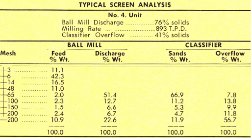
The three classifier overflows flow by gravity at 40% solids to Super Conditioners, consisting of one 6′ x 6′ and two 6′ x 8′ conditioners and wood stave tanks having a retention time of five minutes. The combined overflow from the conditioners is pumped by a 6″ x 6″ SRL pump which lifts the pulp to a 4-way Pulp Distributor above the flotation floor.
Flotation
The feed pulp is distributed and flows by gravity into four parallel banks of No. 24 (43×43) “Sub-A” Flotation Cells, comprising two 10 – cell machines in each bank, for a total of eighty cells. Distribution and flow through the cells is shown on the accompanying flowsheet. The No. 24 (43×43) “Sub-A” Cells have conical-type impellers and wearing plates with cast side liners, rubber tank bottoms and are not supercharged.
The Flotation Cells have been in operation for varying lengths of time, but conform more or less to the following schedule: No. 1 bank since 1953; No. 2 bank since 1956; No. 3 bank since November 1959 and No. 4 bank since June 1960. There have been no repairs to cell liners or bottoms in any cells nor replacements to impellers in No. 3 and No. 4 banks. In the No. 1 bank there have been two sets of impellers and wearing plates and in the No. 2 bank one set replaced. This maintenance is considered low, considering the relatively coarse grind and the high degree of performance maintained.
Flotation pulp enters the rougher cells at 30% to 32% solids and at a controlled pH of 10.6 to 10.8. The temperature is uncontrolled, varying with the season between 46°F and 68°F.
Reagents
Dry flotation reagents such as hydrate lime and sodium sulphite are fed by Belt and Cone Feeders. All other reagents are wet fed by Clarkson Wet Reagent Feeders. Lime is fed at the rate of .05 lb/ton of ore to the ball mills while the remainder is added to the concentrate thickeners. All the Reagent 208 and .03 lb/ton of tri ethoxy butane are added to the ball mills and conditioners. All of the Z-6 and the remainder of the tri ethoxy butane (.06 lb/ton) are stage-fed to the flotation cells. The sodium sulphite is added to the cleaner cells for pyrite depression.
All reagents, with the exception of the lime, are received in the reagent storage and preparation section of the mill building. Solutions are mixed there and
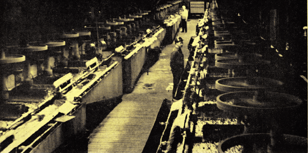
Four identical parallel banks of “Sub-A” Flotation Cells totalling 80 No. 24 (43×43) cells, handle rougher, cleaner, recleaner and scavenger flotation. Tonnage has steadily increased with mill expansion, recovery has increased and total milling costs have been consistently reduced since the mill first operated in 1954.
pumped to storage tanks above the flotation feeder floor from which they flow by gravity to their respective feeders located at the various addition points. Hydrate lime is received in paper bags and stored beneath the catenary ore bin and handled as such to the feeders.

Regrind Circuit
The combined scavenger concentrates and cleaner tailings make up the feed to the regrind circuit. Grinding is done in a 8′ x 27″ Hardinge conical ball mill which is similar to the No. 2 circuit mill and was the first primary grinding mill installed. Ball charge to the mill is made up of 1¼” Ni-hard balls. A 5″ x 5″ SRL pump and two 10″ Krebs cyclones close circuit the unit. Cyclone overflows at a gravity of 1.173 and the minus 200-mesh pulp returns to the flotation feed.

Concentrate Dewatering
Concentrate pulps are collected from the first two or three rougher cells and from the recleaner cells in each bank of flotation machines and are pumped through two parallel 8-inch cyclones where about 50% of the solids goes directly as cyclone underflow to three 6′ Disc Filters. The cyclone overflows are thickened in two 30′ x 12′ wood-stave thickeners equipped with Dorr mechanisms. The underflow from the thickeners, at 50%-60% solids, is pumped by 2″ Dorr duplex diaphragm pumps to the filters. Thickener overflow water runs through a third similar thickener before being returned to the grinding circuit steady-head tank. This thickener mechanism is run only at clean-out time which is every two to three months. Lime addition at the thickeners maintains a pH of 11.0.
The 6′ Disc Filters are two units of 4 discs and one unit of 2 discs. Vacuum is maintained at 25.0″ Hg by two 14″ x 7″ Canadian Ingersoll Rand horizontal type pumps and one Gardner Model AAE-1003 vacuum pump. Filtrate is removed by Canadian Allis Chalmers 2″ x 1½” D pump. Mechanical maintenance on the filters has been negligible except for annual inspection and cleaning. About 50 bag-sections are used per month.
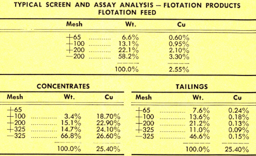
Concentrates totalling 230 to 240 tons per day, and containing 9.5% moisture, 25.0% Cu, 0.25 oz. Au and 3.0 Ag per ton are conveyed over an 18″ Merrick type S.V. Weightometer and loaded in 70-ton open-gondola type railway cars for shipment to the Noranda smelter.
Sand Plant
In the preparation of mine backfill the tailings are pumped through two stages of 20-inch Krebs cyclones. In the sand plant about 50 percent of the weight of solids handled are recovered as sand having a percolation rate of five to seven inches per hour. The settled sands are stored in two 175-ton wood-stave tanks and distributed as needed underground through a 3-inch diamond drill hole located directly below the tanks. The amount of sand prepared averages 10,000 tons per month. Additional equipment is presently being installed for the preparation of sand grout for covering cut-and- fill stope floors.
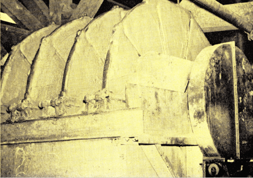
One of three 6′ Disc Filters used to dewater copper concentrates. The copper concentrates discharge onto a common conveyor belt which transports the concentrates to rail road cars. Since the mill commenced operation in 1954 over 2 billion pounds of concentrates averaging 24.71% copper has been produced.

Three 20-inch cyclones are used in the sand-fill plant. To give high percolation rates, two-staging and water injection are used at times to minimize slime entrainment. Average production of sand-fill is 10,000 tons per month.
Pumping
All pulps in the milling circuit are handled by SRL-type pumps. Vertical lift and SRL-type pumps are used intermittently at the various sumps while Cameron-type pumps handle high pressure and makeup water to the steady-head tank. There are also two stand-by pumps for classifier overflows and tailings disposal. It may be noted in the accompanying table that repairs have been light. These, with one exception, have come after prolonged service and were confined mainly to the older pumps used on classifier overflow service during various stages of expansion.
Tailings Disposal
The flotation tailings are elevated in the mill building by pumping and join slimes from the sand preparation plant to flow by gravity through a 10-inch wood-stave pipe to the disposal area, some 1,500 feet northwest of the mill building. This area is in a natural basin a half mile wide extending about a mile below the millsite. At the lower end an earthen dam forms a spillway impounding a large pond of water for further settling of fine tailings.

Sampling and Laboratory
All samples used for metallurgical accounting are taken by 21″ Automatic Samplers cutting the streams every 20 minutes. These samplers, located as shown on the flowsheet, are classifier overflow, flotation tailings and concentrates. The classifier overflow sample provides the assay of the mill feed. The samples
are prepared on both an 8-hour and a 24-hour basis.
The official mill feed tonnage is obtained on a monthly basis from the Merrick weightometer reading of the fine ore, bin inventory and an average of the daily moisture analyses. The standard procedure is to
calibrate the weightometer monthly unless the weekly check indicates more frequent calibration is required. Calculation of the daily feed to each mill is by feed-
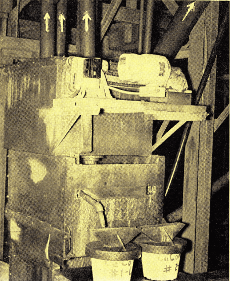
A 21″ Automatic Sampler is mounted on the common pump sump to sample copper concentrates prior to dewatering. Concentrates from all four banks of “Sub-A” Flotation Machines join in this sump. Launders divide the sample into two pails. Sampler takes one cut each 20 minutes, the sample taken as the cutter moves to the left is in one pail while the sample cut on movement to the right is kept in the second pail.
belt weight, revolution counter and moisture analysis.
A modern assay and analytical laboratory is housed in a separate building and provides gold, silver and copper assays on a routine basis. Fire assaying of precious metals and copper analysis by the short iodide method are the procedures employed. On car samples of concentrates and return smelter samples the copper is assayed by the electrolytic method. In addition there is a mill laboratory equipped to handle flotation tests, sieve and copper analyses.
Power
Three phase, 60-cycle power is purchased from the Quebec Hydro-Electric Commission, being transmitted from the main system at St. Felicien 160 miles to Chapais. Line voltage is 161,000 for the first 137 miles and 25,000 for the remaining 23 miles at the Chapais end. For use in the mill the power is transformed to 2,300 volts for the Tricone mill motors, to 550 volts for all other motors and to 115 volts for lighting, etc.
Peak load at the mine is 6,476 Kw at a load factor of 73.0%, costing $0,011 per kw hr. or $0.44 per ton milled. About one-third of the power is used directly in milling as follows:
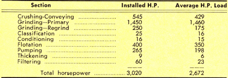
Standby power for non-operating emergency requirements is provided by two Dominion diesel-generator sets consisting of one 400-H.P. 5-D-80 diesel engine connected to a 250-Kw generator and one 250-H.P. 3-D-80 diesel connected to a 150-Kw generator.
Water
Water is pumped from Presquile Lake, five miles from the mine, through a buried, cast iron and wood- stave, 16-inch diameter pipe line. The cast iron sections are used in soft muskeg. Water delivery is by a C.A.C. 2,000 Imp. gal. per min. pump operating against a total head of 308 ft. and directly connected to a 250- H.P. motor. The mill water consumption is 650 g.p.m. with an additional 400 g.p.m. required intermittently during backfill sand plant operation. Water is supplied to the mill from outside water tanks through 6″ mains at 25 p.s.i.g. The natural pH of the water is 8.1.
Personnel
The mill operating crew totals 30 employees, classified as follows:

