Table of Contents
- Ball Mill Maintenance Manual
- On Mill Installation and Maintenance
- Ball Mill Concrete Foundations
- Grinding Mill FOUNDATION
- GROUTING
- Ball Mill Sole Plate
- PINION BEARINGS
- Mill TRUNNION BEARINGS
- Mill SHELL Liner & HEAD Liners
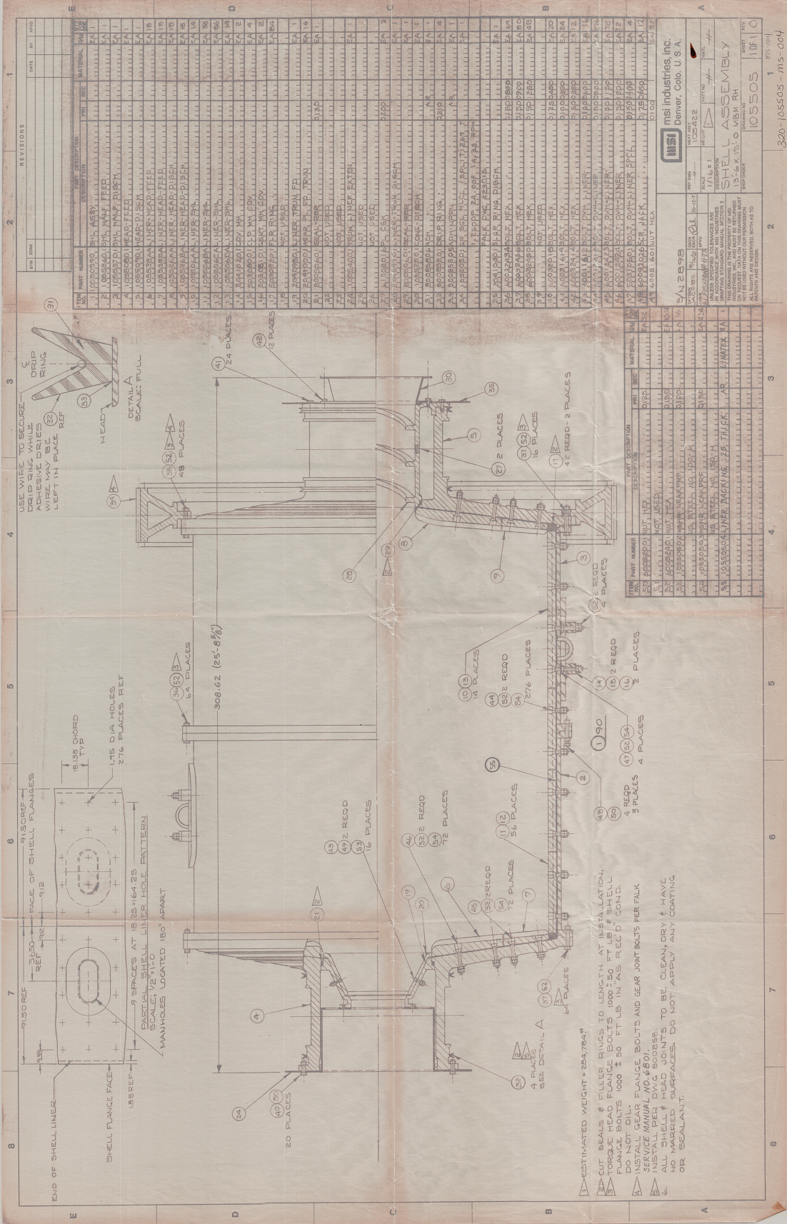
- How to Mount a Ball Mill
- TRUNNION BEARING SEALS
- Mill TRUNNION LINERS
- Ball Mill Lubrication Procedure
- PINION BEARING LUBRICATION
- How to Start a Ball Mill or Rod Mill
- Ball Mill Relining
- GRATE DISCHARGE HEAD
- General Ball Mill Maintenance
Am sure your Ball Mill is considered the finest possible grinding mill available. As such you will find it is designed and constructed according to heavy duty specifications. It is designed along sound engineering principles with quality workmanship and materials used in the construction of the component parts. Your Ball Mill reflects years of advancement in grinding principles, materials, and manufacturing techniques. It has been designed with both the operators and the erectors viewpoints in mind. Long uninterrupted performance can be expected from it if the instructions covering installation and maintenance of the mill are carried out. You may be familiar with installing mills of other designs and manufacture – much lighter in construction. Your Ball is heavy and rugged. It should, therefore, be treated accordingly with due respect for its heavier construction.
Ball Mill Maintenance Manual
The purpose of this manual is to assist you in the proper installation and to acquaint you a bit further with the assembly and care of this equipment. We suggest that these instructions be read carefully and reviewed by everyone whenever involved in the actual installation and operation of the mill. In reading these general instructions, you may at times feel that they cover items which are elementary and perhaps not worthy of mention; however in studying hundreds of installations, it has been found that very often minor points are overlooked due to pressure being exerted by outside influences to get the job done in a hurry. The erection phase of this mill is actually no place to attempt cost savings by taking short cuts, or by-passing some of the work. A good installation will pay dividends for many years to come by reduced maintenance cost. With the modern practice of specialized skills and trades, there is often a line drawn between responsibilities of one crew of erectors and another. Actually the responsibility of installation does not cease with the completion of one phase nor does it begin with the starting of another. Perhaps a simple rule to adopt would be “DO NOT TAKE ANYTHING FOR GRANTED”. This policy of rechecking previously done work will help guarantee each step of the erection and it will carefully coordinate and tie it into subsequent erection work. To clarify or illustrate this point, take the example of concrete workers completing their job and turning it over to the machinist or millwright. The latter group should carefully check the foundation for soundness and correctness prior to starting their work.
Sound planning and good judgement will, to a great extent, be instrumental in avoiding many of the troublesome occurrences especially at the beginning of operations. While it is virtually impossible to anticipate every eventuality, nevertheless it is the intention of this manual to outline a general procedure to follow in erecting the mill, and at the same time, point out some of the pitfalls which should be avoided.
On Mill Installation and Maintenance
Before starting the erection of the mill, adequate handling facilities should be provided or made available, bearing in mind the weights and proportions of the various parts and sub-assemblies. This information can be ascertained from the drawings and shipping papers.
The gearing, bearings, and other machined surfaces have been coated with a protective compound, and should be cleaned thoroughly with a solvent, such as “Chlorothene”, (made by Dow Chemical). Judgement should be exercised as to the correct time and place for cleaning the various parts. Do not permit solvents, oil or grease to come in contact with the roughened top surfaces of the concrete foundation where grouting is to be applied; otherwise proper bonding will not result.
After cleaning the various parts, the gear and pinion teeth, trunnion journals and bearings, shafting and such, should be protected against rusting or pitting as well as against damage from falling objects or weld splatter.
All burrs should be carefully removed by filing or honing.
Unless otherwise arranged for, the mill has been completely assembled in our shop. Before dismantling, the closely fitted parts were match marked, and it will greatly facilitate field assembly to adhere to these match marks.
The surfaces of all connecting joints or fits, such as shell and head flanges, trunnion flanges, trunnion liner and feeder connecting joints, should be coated with a NON-SETTING elastic compound, such as Quigley “O-Seal”, or “Permatex” to insure against leakage and to assist in drawing them up tight. DO NOT USE WHITE LEAD OR GREASE.
The mill should rotate in the proper direction. The mill gear should be lifted by the pinion causing a downward pressure on the pinion shaft bearing.
Mills are made either right or left “hand”. There are two methods of identifying the “hand” of the mill.
- When standing at the feed end of the mill, and facing the mill, if the mill rotates clockwise, it is a right hand mill. If it rotates counter clockwise, it is a left hand mill.
- When standing at the discharge end of the mill, and facing the mill, if the drive is on the right hand side it is a right hand mill. If the drive is in the left hand side, it is a left hand mill.
Parts which are affected by the hand of the mill are easily identified by referring to the parts list. In general they include the feeder, feed trunnion liner, discharge trunnion liner if it is equipped with a spiral, spiral type helical splitter, and in some cases the pan liners when they are of the spiral type. When both right and left hand mills are being assembled, it is imperative that these parts which involve hand be assembled in the correct mill.
Ball Mill Concrete Foundations
Adequate foundations for any heavy equipment, and in particular grinding mills, are extremely important to assure proper operation. The foundation should preferably be in one piece, that is, with a reinforced slab footing (so called “mat”) extending under both trunnion bearing foundations as well as the pinion bearing foundation. If possible or practical, it should be extended to include also the motor and drive. With this design, in the event of some movement, the mill and foundation will tend to move as a unit. ANY SLIGHT SETTLING OF FOUNDATIONS WILL CAUSE BEARING AND GEAR MISALIGNMENT, resulting in excessive wear and higher maintenance costs. It has been found that concrete foundations on a weight basis should be at least 1½ times the total weight of the grinding mill with its grinding media.
Allowable bearing pressure between concrete footings and the soil upon which the foundation rests should first be considered. The center of pressure must always pass through the center of the footing. Foundations subject to shock should be designed with less unit pressure than foundations for stationary loads. High moisture content in soils reduces the amount of allowable specific pressure that the ground can support. The following figures may be used for preliminary foundation calculations.

An accurate determination by experimentation and close examination should be made to check the exact soil characteristics.
Portland cement mixed with sand and aggregate in the proper proportions has come to be standard practice in making concrete. For general reference cement is usually shipped in sacks containing one cubic foot of material. A barrel usually holds 4 cubic feet. Cement will deteriorate with age and will quickly absorb moisture so it should be stored in a dry place. For best results the sand and gravel used should be carefully cleaned free of humus, clay, vegetal matter, etc.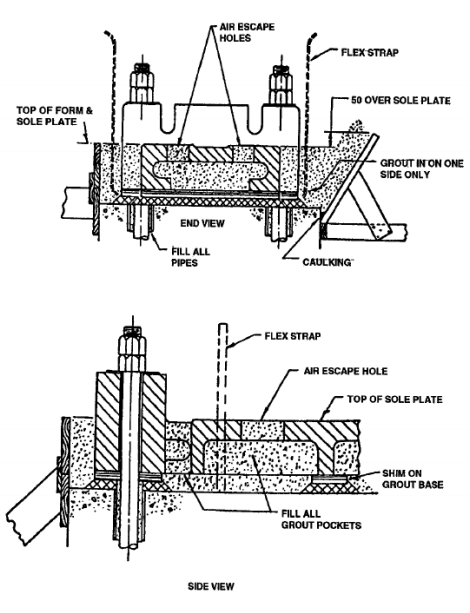
Concrete may be made up in different mixtures having different proportions of sand and aggregate. These are expressed in parts – for example a 1:2:4 mixture indicates one bag of cement, 2 cubic feet of sand, and 4 cubic feet of gravel. We recommend a mixture of 1:2:3 for ball mill and rod mill foundations. The proper water to sand ratio should be carefully regulated since excess water increases the shrinkage in the concrete and lends to weaken it even more than a corresponding increase in the aggregate. Between 5½ to 8½ gallons of water to a sack of cement is usually recommended, the lower amount to be used where higher strength is required or where the concrete will be subject to severe weathering conditions.
Detailed dimensions for the concrete foundation are covered by the foundation plan drawing submitted separately. The drawing also carries special instructions as to the allowance for grouting, steel reinforcements, pier batter, foundation bolts and pipes. During concrete work, care should be taken to prevent concrete entering the pipes, surrounding the foundations bolts, which would limit the positioning of the bolts when erecting the various assemblies. Forms should be adequately constructed and reinforced to prevent swell, particularly where clearance is critical such as at the drive end where the gear should clear the trunnion bearing and pinion bearing piers.
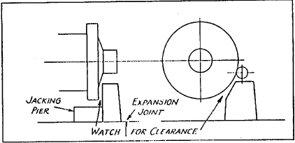
Where a concrete floor slab is adjacent to the mill foundations, an expansion joint should be used.
For convenience in maintenance, the mill foundations should be equipped with jacking piers. These will allow the lifting of one end of the mill by use of jacks in the event maintenance must be carried out under these conditions.
Grinding Mill FOUNDATION
Adequate foundations for any heavy equipment, and in particular Marcy grinding mills, are extremely important to assure proper operation of that equipment. Any slight settling of foundations will cause bearing and gear misalignment, resulting in excessive wear and higher maintenance costs. It has been found that concrete foundations on a weight basis should be approximately 1½ times the total weight of the grinding mill with its grinding media.
Allowable bearing pressure between concrete footings and the soil upon which the foundation rests should first be considered. The center of pressure must always pass through the center of the footing. Foundations subject to shock should be designed with less unit pressures than foundations for stationary loads. High moisture content in soils reduces the amount of allowable pressure that that material can support. The following figures may be used for quick foundation calculations:
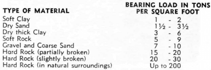
An accurate determination by experimentation and close examination should be made to check the exact soil characteristics.
Portland cement mixed with sand and aggregate in the proper proportions has come to be standard practice in making concrete. For general reference cement is usually shipped in sacks containing one cubic foot of material. A barrel usually consists of 4 cubic feet. Cement will deteriorate with age and will quickly absorb moisture so it should be stored in a cool, dry place. The sand and gravel used should be carefully cleaned for best results to be sure of minimizing the amount of sedimentation in that material.
Concrete may be made up in different mixtures having different proportions of sand and aggregate. These are expressed in parts — for example a 1:2:4 mixture indicates one bag of cement, 2 cubic feet of sand, and 4 cubic feet of gravel. We recommend a mixture of 1:2:3 for ball mill and rod mill foundations. The proper water to sand ratio should be carefully regulated since excess water will tend to weaken the concrete even more than corresponding variations in other material ratios. Between 5½ to 8½ gallons of water to a sack of cement is usually recommended, the lower amount to be used where higher strength is required or where the concrete will be subject to severe weathering conditions.
GROUTING
We recommend the use of a non-shrinking grout, and preferably of the pre-mixed type, such as “Embeco”, made by the Master Builders Company of Cleveland, Ohio. Thoroughly clean the top surfaces of the concrete piers, and comply with the instructions of the grouting supplier.
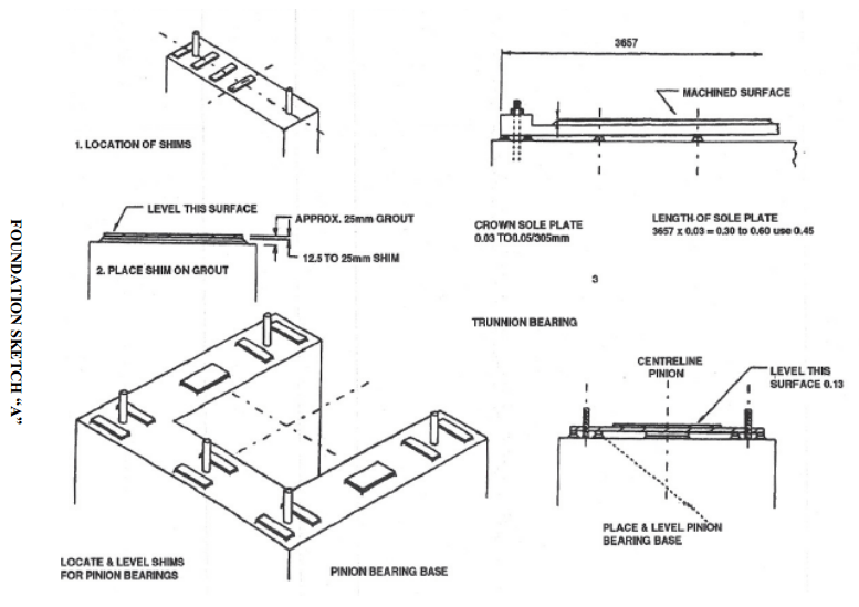
Before grouting the various parts, they should be carefully leveled and aligned by adequate shimming. We recommend the following procedure.
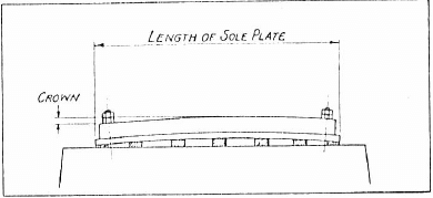
1. Establish vertical and horizontal centerline of mill and pinion shaft against the effects of this, we recommend that the trunnion bearing sole plate be crowned so as to be higher at the center line of the mill. This is done by using a higher shim at the center than at the ends and tightening the foundation bolts of both ends.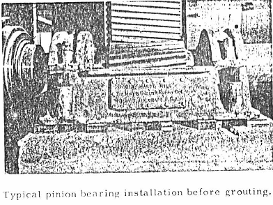
Ball Mill Sole Plate
This crown should be between .002″ and . 003″, per foot of length of sole plate. For example, if the sole plate is about 8′ long, the crown should be between .016″ and .024″.
After all shimming is completed, the sole plate and bases should be grouted in position. Grouting should be well tamped and should completely fill the underside of the sole plate and bases. DO NOT REMOVE THE SHIMS AFTER OR DURING GROUTING. When the grout has hardened sufficiently it is advisable to paint the top surfaces of the concrete so as to protect it against disintegration due to the absorption of oil or grease.
If it is felt that sufficient accuracy in level between trunnion bearing piers cannot be maintained, we recommend that the grouting of the sole plate under the trunnion bearing opposite the gear end be delayed until after the mill is in place. In this way, the adjustment by shimming at this end can be made later to correct for any errors in elevation. Depending on local climatic conditions, two to seven days should he allowed for the grouting to dry and set, before painting or applying further loads to the piers.
PINION BEARINGS
Pinion bearings are provided of either the sleeve type or anti-friction type. Twin bearing construction may use either individual sole plates or a cast common sole plate. The unit with a common sole plate is completely assembled in our shop and is ready for installation. Normal inspection and cleaning procedure should be followed. Refer to the parts list for general assembly. These units are to be permanently grouted in position and, therefore, care should be taken to assure correct alignment.
Mill TRUNNION BEARINGS
The trunnion bearing assemblies can now be mounted on their sole plates. If the bearings are of the swivel type, a heavy industrial water-proof grease should be applied to the spherical surfaces of both the swivels and the bases. Move the trunnion bearings to their approximate position by adjustment of the set screws provided for this purpose.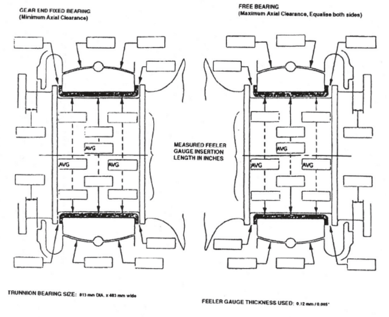
Mill SHELL Liner & HEAD Liners
Grate discharge heads for ball mills are completely assembled in the shop, with grates, clamp bars, pan liners, and center discharge liners in place.
Depending upon available handling facilities, the head or shell can be lined separately in a repair bay, or after assembly of the mill proper in the trunnion bearings.
In the case of ball mills, all internal wearing parts will pass through the manhole, whereas in the case of open end rod mills they will pass through the discharge trunnion opening. When lining the shell, start with the odd shaped pieces around the manhole opening if manholes are furnished. Rubber shell liner backing should be used with all cast type rod mills shell liners. If the shell liners are of the step type, they should be assembled with the thin portion, or toe, as the leading edge with respect to rotation of the mill.
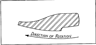
If the liners are of a special directional type, or in any other way complicated, a separate layout drawing is submitted with the other drawings of the mill.
Lorain liners for the shell are provided with special round head bolts, with a waterproof washer and nut. All other cast type liners for the head and shell are provided with oval head bolts with a cut washer and nuts. Except when water proof washers are used, it is advisable to wrap four or five turns of candle wicking around the shank of the bolt under the cut washer. Dip the candle wicking in white lead. All liner bolt threads should be dipped in graphite and oil before assembly. All liner bolt cuts should be firmly tightened by use of a pipe extension on a wrench, or better yet, by use of a torque wrench. The bolt heads should be driven firmly into the bolt holes with a hammer.
In order to minimise the effect of pulp race, we recommend that the spaces between the ends of the shell liners and the head liners or grates be filled with suitable packing. This packing may be in the form of rubber belting, hose, rope or wood.
How to Mount a Ball Mill
If adequate overhead crane facilities are available, the heads can be assembled to the shell with the flange connecting bolts drawn tightly. Furthermore, the liners can be in place, as stated above, and the gear can be mounted, as covered by separate instructions. Then the mill can be taken to its location and set in place in the trunnion bearings.
If on the other hand the handling facilities are limited it is recommended that the bare shell and heads be assembled together in a slightly higher position than normal. After the flange bolts are tightened, the mill proper should be lowered into position. Other intermediate methods may be used, depending on local conditions.
In any event, just prior to the lowering of the mill into the bearings the trunnion journal and bushing and bases should be thoroughly cleaned and greased. Care should be taken not to foul the teeth in the gear or pinion. Trunnion bearing caps should be immediately installed, although not necessarily tightened, to prevent dirt settling on the trunnions. The gear should be at least tentatively covered for protection.
TRUNNION BEARING SEALS
If oil or grease seals are supplied for the trunnion bearings, they should be uncoiled and allowed to warm up to room temperature so that they assume their approximate curvature before assembly.
IMPORTANT. Unless the millwright or operator is familiar with this type of seal, there is a tendency to assume that the oil seal is too long because of its appearance when held firmly around the trunnion. It is not the function of the brass oil seal band to provide tension for effective sealing. This is accomplished by the garter spring which is provided with the oil seal.
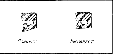
Therefore, we strongly recommend that the length of these brass oil seal-bands not be altered, and furthermore, that caution be used before cutting the rubber oil seal to length.
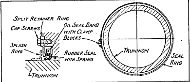
Assemble the oil seal with the spring in place, and with the split at the top. Encircle the oil seal with the band, keeping the blocks on the side of the bearing at or near the horizontal center line so that when in place they will fit between the two dowel pins on the bearing, which are used to prevent rotation of the seal.
Moderately tighten up the cap screws at the blocks, pulling them together to thus hold the seal with its spring in place. If the blocks cannot be pulled snuggly together, then the oil seal may be cut accordingly. Oil the trunnion surface and slide the entire seal assembly back into place against the shoulder of the bearing and finish tightening. Install the retainer ring and splash ring as shown.
Mill TRUNNION LINERS
In most cases the trunnion liners are already mounted in the trunnions of the mills. If not, they should be assembled with attention being given to match marks or in some cases to dowel pins which are used to locate the trunnion liners in their proper relation to other parts.
Mill FEED CHUTE
If a scoop feeder, combination drum scoop feeder or drum feeder is supplied with the mill, it should be mounted on the extended flange of the feed trunnion liner, matching the dowel pin with its respective hole. The dowel pin arrangement is provided only where there is a spiral in the feed trunnion liner. This matching is important as it fixes the relationship between the discharge from the scoop and the internal spiral of the trunnion liner. Tighten the bolts attaching the feeder to the trunnion liner evenly, all around the circle, seating the feeder tightly and squarely on its bevelled seat. Check the bolts holding the lips and other bolts that may require tightening. The “beveled seat” design is used primarily where a feeder is provided for the trunnion to trunnion liner connection, and the trunnion liner to feeder connection. When a feeder is not used these connecting joints are usually provided by a simple cylindrical or male and female joint.
If a spout feeder is to be used, it is generally supplied by the user, and should be mounted independently of the mill. The spout should project inside the feed trunnion liner, but must not touch the liner or spiral.
Ball Mill FEED BOX
Ordinarily the feed box for a scoop tender is designed and supplied by the user. The feed box should be so constructed that it has at least 6″ clearance on both sides and at the bottom of the scoop. This clearance is measured from the outside of the feed scoop.
The feed box may be constructed of 2″ wood, but more often is made of 3/16″ or ¼” plate steel reinforced with angles. In the larger size mills, the lower portion is sometimes made of concrete. Necessary openings should be provided for the original feed and the sand returns from the classifiers when in closed circuit.
Horizontal and vertical joints should be provided for maintenance of the feeder. These joints should be designed with consideration for head room and accessibility.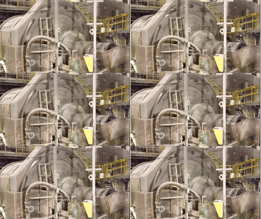
Ball Mill GEAR GUARD
A plate steel gear guard is furnished with the mill for safety in operation and to protect the gear and pinion from dirt or grit. As soon as the gear and pinion have been cleaned and coated with the proper lubricant, the gear guard should be assembled and set on its foundation.
DISCHARGE HOUSING “Doghouse”
Most Rod Mills are provided with a discharge housing mechanism mounted independently of the mill. This unit consists of the housing proper, plug door, plug shaft, arm, and various hinge pins and pivot and lock pins. The door mechanism is extra heavy throughout and is subject to adjustment as regard location. Place the housing proper on the foundation, level with steel shims and tighten the foundation bolts. The various parts may now be assembled to the housing proper and the door plug can be swung into place, securing it with the necessary lock pins.
After the mill has been completely assembled and aligned, the door mechanism centered and adjusted, and all clearances checked, the housing base can be grouted. The unit should be so located both vertically and horizontally so as to provide a uniform annular opening between the discharge plug door and the head liners.
This space should be between 1″ and 1½” to provide for adequate discharge and at the same time to prevent against rod ends becoming entangled at this point.
In some cases because of space limitation, economy reasons, etc., the mill is not equipped with separate discharge housing. In such a case, the open end low discharge principal is accomplished by means of the same size opening through the discharge trunnion but with the plug door attached to lugs on the head liner segments or lugs on the discharge trunnion liner proper. In still other cases, it is sometimes effected by means of an arm holding the plug and mounted on a cross member which is attached to the bell of the discharge trunnion liner. In such cases as those, a light weight sheet steel discharge housing is supplied by the user to accommodate the local plant layout in conjunction with the discharge launder.
Ball Mill Lubrication Procedure
TRUNNION BEARING LUBRICATION. For the larger mills with trunnion bearings provided with oil seals, we recommend flood oil lubrication. This can be accomplished by a centralized system for two or more mills, or by an individual system for each mill. We recommend the individual system for each mill, except where six or more mills are involved, or when economy reasons may dictate otherwise.
In any event oil flow to each trunnion bearing should be between 3 to 5 gallons per minute. The oil should be adequately filtered and heaters may be used to maintain a temperature which will provide proper filtration and maintain the necessary viscosity for adequate flow. The lines leading from the filter to the bearing should be of copper tubing or pickled piping. The drain line leading from the bearings to the storage or sump tank should be of adequate size for proper flow, and they should be set at a minimum slope of ¼” per foot, perferably ½” per foot. Avoid unnecessary elbows and fittings wherever possible. Avoid bends which create traps and which might accumulate impurities. All lines should be thoroughly cleaned and flushed with a solvent, and then blown free with air, before oil is added.
It is advisable to interlock the oil pump motor with the mill motor in such a way that the mill cannot be started until after the oil pump is operating. We recommend the use of a non-adjuslable valve at each bearing to prevent tampering.
The smaller mills, which are not generally provided with oil seals, may be lubricated by means of drip oil or brick grease.
When using the drip oil system it is advisable to place wool yarn or waste inside a canvas porous bag to prevent small pieces of the wool being drawn down into the trunnion journal. If brick grease is used, care should be taken in its selection with regard to the range of its effective temperature. In other words, it should be pointed out that brick grease is generally designed for a specific temperature range. Where the bearing temperature does not come up to the minimum temperature rating of the brick grease, the oil will not flow from it, and on the other hand if the temperature of the bearing exceeds the maximum temperature rating of the brick grease, the brick is subject to glazing; therefore, blinding off of the oil. This brick should be trimmed so that it rests freely on the trunnion journal, and does not “hang up”, or bind on the sides of the grease box.
When replacing the brick grease, remove the old grease completely. Due to the extended running time of brick grease, there is usually an accumulation of impurities and foreign matter on the top surface, which is detrimental to the bearing.
During the breaking-in period, that is, during the first few weeks of operation it is advisable to supplement brick grease with the oil drip system, until the bearing temperature has been stabilized.
PINION BEARING LUBRICATION
Where anti-friction bearings are supplied, they are adequately sealed for either grease or oil lubrication. If a flood system is used for the trunnion bearings and it is adequately filtered, it can then be used for pinion bearings with the same precautions taken as mentioned above, with a flow of ½ to 1½ gallons per minute to each bearing.
Where pinion bearings of the sleeve type are supplied with the mill, these are lubricated by ring or chain oiling, and oil gauges are supplied to indicate the proper level of oil.
GEAR LUBRICATION
There are many good gear lubricants on the market, but we recommend the use of one of the Crater Compound types.
These lubricants can be applied by hand, but we highly recommend some type of spray system, whether it be automatic, semi-automatic or manually operated. It has been found that it is best to lubricate gears frequently with small quantities.
COUPLING AND GEAR REDUCER LUBRICATION
Instructions covering these items are covered by separate pamphlet. Refer to the Lubrication Chart.
How to Start a Ball Mill or Rod Mill
Start the lubrication system and run it for about ten minutes, adjusting the oil flow at each bearing. Check all of the bolts and nuts on the mill for tightness and remove all ladders, tools and other obstructions prior to starting the mill.
Before starting the mill, even though it is empty, we recommend that it be jogged one or two revolutions for a check as to clearance of the gear and its guard, splash rings, etc. The trunnion journal should also be checked for uniform oil film and for any evidence of foreign material which might manifest itself through the appearance of scratches on the journal. If there are any scratches, it is very possible that some foreign material such as weld splatter may have been drawn down into the bushing, and can be found imbedded there. These particles should be removed before proceeding further.
If everything is found to be satisfactory, then the mill should be run for ten to fifteen minutes, and stopped. The trunnion bearings should be checked for any undue temperature and the gear grease pattern can be observed for uniformity which would indicate correct alignment.
If everything is clear, the mill can be run for from six to eight hours, observing any abnormal reactions at the trunnion bearings, pinion bearings, and gear and pinion mesh.
It should be noted that with an empty mill the reactions and operating characteristics of the bearings and gearing at this point are somewhat different than when operating with a ball or rod charge. Gear noises will be prominent and some vibration will occur due to no load and normal back-lash. Furthermore, it will be found that the mill will continue to rotate for some time after the power is shut off. Safety precautions should therefore he observed, and no work should be done on the mill until it has come to a complete stop.
We have now reached the point where a half ball or rod charge can be added, and the mill run for another six to eight hours, feeding approximately half the anticipated tonnage. The mill should now be stopped, end the gear grease pattern checked, and gear and pinion mesh corrected, if necessary, according to separate instructions.
By this time it will probably be evident that some of the bolts, particularly the shell liner bolts, have become loosened. They should be thoroughly tightened again.
Be sure to check those bolts and nuts which might not manifest looseness by leakage. These would include gear and flange connecting bolts, trunnion connecting bolts and studs.
Where bolt leakage might foul the gear or bearings, stop the mill at once and take the necessary corrective steps including cleaning all pulp or sand from the vital parts.
The full charge of balls or rods can now be added, as well as the full amount of feed, and after a run of about four to six days, ALL BOLTS SHOULD AGAIN BE RETIGHTENED, and the gear and pinion checked again, and adjusted if necessary.
Where “starting jacks” are provided for the trunnion bearings of the larger sized mills, they should be filled with the same oil that is used for the lubrication of the trunnion bearings. Before starting the mill they should be pumped so as to insure having an oil film between the journal and the bushing.
Ball Mill Relining
When relining any part of the mill, clean away all sand from the parts to be relined before putting in the new liners. For the head liners and shell liners you may then proceed in the same manner used at the time of the initial assembly.
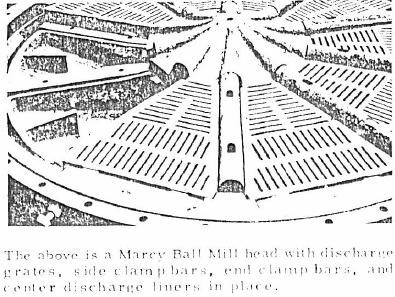
GRATE DISCHARGE HEAD
Before relining the grate type discharge head, it is advisable to refer to the assembly drawings and the parts list. Because of such limitations as the size of the manhole opening, and for various other reasons, it will be found that the center discharge liner and cone designs vary. The cone may be a separate piece or integral with either the trunnion liner, or the router discharge liner. Furthermore, it will be found in some mills that the center discharge liner is held by bolts through the discharge head, whereas in other cases it depends upon the clamping effect of grates to hold it in position. In any event, the primary thing to remember in assembling the discharge grate head parts is the fact that the grate should be first drawn up tightly towards the center discharge liner by adjusting the grate set screws located at the periphery of the discharge head. This adjustment should be carried out in progressive steps, alternating at about 180° if possible and in such a manner that, the center discharge liner does not become dislodged from its proper position at the center of the mill. These grate set screws should be adjusted with the side clamp bar bolts loosened. After the grates have been completely tightened with the set screws, check for correct and uniform position of each grate section. The side clamp bar bolts may now be lightened, again using an alternate process. This should result in the side clamp bars firmly bearing against the beveled sides of the grates. The side clamp bars should not hear against the lifter liners.
When new pan liners are installed, they should be grouted in position so as to prevent pulp race in the void space between the discharge head and the pan liner. Another good method of preventing this pulp race is the use of the sponge rubber which can be cemented in place.
General Ball Mill Maintenance
After the mill is erected, in order to avoid overlooking both obvious and obscure installation details, we recommend the use of a check list. This is particularly recommended for multiple mill installations where it is difficult to control the different phases of installation for each and every mill. Such a check list can be modeled after the following:
No. 1 – Connecting Bolts drawn tight.
A. Head and Shell flange bolts.
B. Gear Connecting, bolts.
No. 2 – Trunnion studs or bolts drawn up tight.
No. 3 – Trunnion liner and feeder connecting bolts or studs drawn up tight.
No. 4 – Feeder lip bolts tightened.
No. 5 – Liner bolts drawn up tight.
No. 6 – Gear.
A. Concentric
B. Backlash
C. Runout
D. Joint bolts drawn up tight.
No. 7 – Coupling and Drive alignment and lubrication.
No. 8 – Bearings and Gearing cleaned and lubricated.
No. 9 – Lubrication system in working order with automatic devices including alarms and interlocking systems.
We further recommend that during the first thirty to sixty days of operation, particular attention be given to bolt tightness, foundation settlement and condition of the grouting. We suggest any unusual occurrence be recorded so that should trouble develop later there may be a clue which would simplify diagnosing and rectifying the situation.
As a safety precaution, and in many cases in order to comply with local safety regulations, guards should be used to protect the operators and mechanics from contact with moving parts. However, these guards should not be of such a design that will prevent or hinder the close inspection of the vital parts. Frequent inspection should be made at regular intervals with particular attention being given to the condition of the wearing parts in the mill. In this way, you will be better able to anticipate your needs for liners and other parts in time to comply with the current delivery schedules.
When ordering repair or replacement parts for your mill, be sure to identify the parts with the number and description as shown on the repair parts list, and specify the hand and serial number of the mill.
By following the instructions outlined in this manual, mechanical malfunctions will be eliminated. However, inadvertent errors may occur even under, the most careful supervision. With this in mind, it is possible that some difficulties may arise. Whenever any abnormal mechanical reactions are found, invariably they can be attributed to causes which though sometimes obvious are often hidden. We sight herewith the most common problems, with their solutions.
No. 1 – GEAR AND PINION VIBRATION.
Cause A – EXCESSIVE BACKLASH. Move mill gear toward the pinion and check for proper backlash per separate instructions.
Cause B – INSUFFICIENT BACKLASH. Move the mill gear away from the pinion and check for proper backlash per separate instructions.
Cause C – OUT OF LEVEL. Realign the gear and pinion by the use of shimming between the trunnion bearing base and the sole plate at the low end.
Cause D – NO LOAD. Vibration under these conditions is a natural consequence as explained in the information under the paragraph entitled “Starting the Mill”.
No. 2 – EXCESSIVE TEMPERATURE OF TRUNNION BEARING.
Cause A – GROUT DISINTEGRATION. Very often when the grouting is not up to specification the vibration from the mill tends to disintegrate the grouting. In most instances the disintegration starts between the sole plate and the top surface of the grouting near or at the vertical centerline of the mill. As this continues, the weight of the mill causes the sole plate and trunnion bearing base to bend with a resultant pinching action at the side of the bearing near the horizontal center line of the mill. This pinching will cut off and wipe the oil film from the journal and will manifest itself in the same manner as if the lubrication supply had been cut off. If the grout disintegration is limited to about . 050″ and does not appear to be progressing further, the situation can be corrected by applying a corresponding amount of shimming between the trunnion bearing base and the sole plate near the centerline of the mill in such a fashion that the trunnion bearing base has been returned to its normal dimensional position. If, on the other hand, the grouting is in excess of . 050″ and appears to be progressing further, it is advisable to shut down operations until the sole plate has been re grouted.
Cause B – HIGH SPOT ON THE BUSHING. While all Ball Mill bushings are scraped in the shop to fit either a jig mandrel or the head proper to which it is to be fitted, nevertheless there is a certain amount of seasoning and dimensional change which goes on in the type of metals used. Therefore if high spots are found, the mill should be raised, the bushings removed and rescraped. Bluing may be used to assist in detecting high spots.
Cause C – INSUFFICIENT OIL FLOW. Increase the oil supply if it is a flood oil system. If brick grease is used, it is possible that the particular grade of brick may not be applicable to the actual bearing temperature. Refer to the remarks in this manual under the paragraph entitled “Lubrication”.
Cause D – EDGE LOADING ON RIGID BEARINGS. This quite obviously must be rectified by the use of shimming between the trunnion bearing base and the sole plate.
Cause E – EXCESSIVE RUBBING ON THE SIDE OF THE BUSHING. This comes about due to the improper setting of the bearings in the longitudinal plane. In some cases, particularly on dry grinding or hot clinker grinding mills, the expansion of the mills proper may account for this condition. In any event, it can be remedied by re-adjusting the bearing base on the sole plate longitudinally at the end opposite the drive.
Cause F – IMPURITIES IN THE OIL SYSTEM. Check the filter element and replace if necessary. Also endeavor to determine the source of entrance of this foreign material getting into the oil supply.
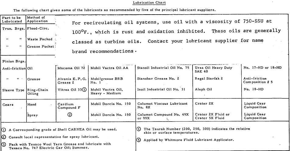
The above chart should be used as a preliminary guide, since it lists those products which are generally available.
There are many more lubricant suppliers, such as E. F. Houghton and Co. , or Lubriplate Division of Fiske Bros. Refining Co. In making your final selection of lubricants, you should consider the actual plant conditions as well as the standardization of lubricants. New and improved lubricants are being marketed, and we, therefore, suggest that you consult your local suppliers.

