There are two basic types of high rate thickener units:
- Lamina or tube settlers and
- solids recirculation units
Lamina Thickeners
They contain space-cutting baffles that intercept settling paths at many levels. Solids settle out onto the baffles and are removed from suspension after settling only a short distance. Where and to the extent that removals are governed by settling rates, such baffles increase the capacity of a space into which they are introduced. They do not increase its volume, so do not increase solids removal where it is governed by flocculation rate and hence by retention time. Thus lamina type units would seem best suited for particulate clarification. (This is settlement unaccompanied by flocculation. Either the solids do not flocculate, or are preflocculated in a separate operation before being introduced into the settler, or flocculate so quickly that flocculation is virtually complete before much sedimentation takes place. The principles of particulate clarification are treated more fully under the section on classification.)
Their applicability for thickening follows a similar pattern. Since they can be considered for some purposes as a stack of unit thickeners (each of extremely shallow depth), they provide a high total overflow area, and thus should accept a high solids loading before a critical zone forms. On the other hand, they do not create additional retention time in a compression zone. On the basis of the currently used Coe and Oevenger model of compression, they would not therefore be expected to increase compression capacity. However, we know the model is faulty. Other models under study predict that with increased settling area and constant retention (therefore small compression depth), compression capacity would be augmented. This is what is observed experimentally. Just how much has, at this time, to be determined by piloting.
The total or equivalent overflow area of a lamina-type unit is the sum of the plan areas of each flow space or compartment formed by the baffle structure (plan area is the compartment area projected onto a horizontal plane). For clarification, the “long tube” test should predict removals, but note that the “long tube” is now very short because the vertical height of any flow compartment is small. In applying long tube data, any areas filled with compressing solids would have to be subtracted from total overflow area to obtain that available for clarification. Proper efficiency factors to use with this type of unit are not generally known, but might be expected to be low. Areal efficiency should be particularly affected and reduced by nonuniform distribution of flow through the various spaces.
Flow patterns in a lamina-type settler are complex because of density effects. These set up rapid circulations that probably cause some remixing and hence low efficiency factors. Under any upper boundary there will be an interface above which clarified liquid is produced as solids settle out below; but are not replenished from above. If the boundary is not level, the film of clarified liquid is squeezed by hydrostatic forces along the boundary in a
rising direction. Thus clear liquid streams upward under any inclined boundary, while thickened suspension streams downward above one. Whether a locally formed stream of clarified liquid remixes to some extent or is joined in the overflow by some streaming elements of unclarified flow, depends upon flow patterns. To the extent it happens, areal and retention efficiencies suffer.
Lamina or tube-type settlers are smaller in size than unit-type settlers, and may be lower in first cost per unit of capacity. In small sizes they are portable. They tie up less suspension in inventory, which may be of economic value if either solids or liquid are valuable. Thus the initial cost of a unit, installed, filled, and ready to go, may be low. They probably cannot produce and handle underflows at as high a solids content as conventional thickeners, and underflows must be much more closely controlled to prevent build-up and overflow of solids. This type of unit is strongly counterindicated if scale formation is a problem or if solids tend to hang up and not slide down sloping surfaces.
Solids Re-circulation Thickener
Solids recirculation units comprise many types. Circulation may be external, internal, or may consist of mixing new feed locally into the thickening zone, as in certain types of “sludge blanket filtration” units. The purpose is to increase the rate at which new feed solids are incorporated into the floe structure and/or to form a floe structure firm enough so that fines do not segregate from it in the feed layer. For feeds in the clarification regime this commonly means mixing into it, one way or another, enough recirculated solids so that the mixed feed will be in the line settling (zone settling) regime.
Remixing settled solids into new feed increases the thickening load and hence the area demand for thickening. As long as thickening area demand is not controlling, this costs nothing. The area has to be there anyway to satisfy overflow rate limitations. At some amount of recirculation thickening, area demand will become larger than that for clarification. The unit size will then increase with increased underflow recirculation. Obviously, the theoretical minimum area needed will occur just as this happens, but in practice recirculation control is not usually precise and does not appear necessary.
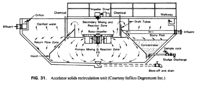
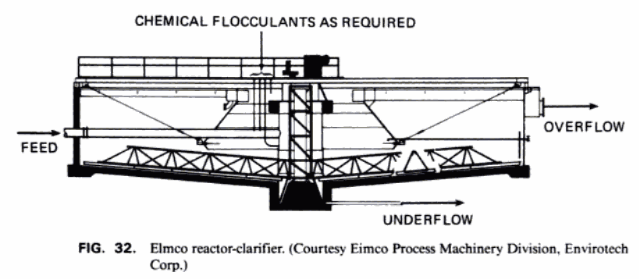
Solids recirculation units can be classified into those having a separate flocculation compartment and those that do not. Fig. 31 shows a typical unit, long used in water treatment, that does have a flocculation compartment. Solids from settling compartment A return to a flocculating chamber B where they are mixed with new feed. Recycled floccules are maintained in suspension by gentle agitation and augment the rate at which feed fines are collected. The mixed feed then flows to the settling chamber. Since the solids are fully flocculated, there is no retention time demand, and since the floe structure is well-formed, it has a high settling rate. This design, however, relies on a sloping bottom to discharge solids. As noted earlier, such designs become impractical in large diameters. Figure 32 shows a competing design, similar in principle but different in configuration. Settled solids are sucked up from a thickening zone by a turbine impeller atop a draft tube and recirculated to a flocculation compartment or enclosure.
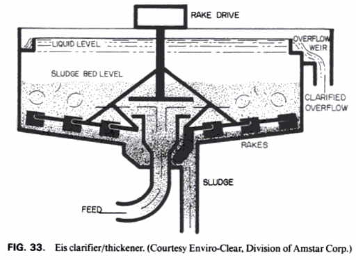
In the design of Fig. 33 the new feed is jetted into the thickening zone in such a way as to mix it thoroughly with the surrounding settled solids. It was developed originally in Australia for clarifying cane sugar juice. Usually flocculants are added to hold the resulting mixed feed solids structure together and to prevent segregation of fines from it. Where, as in cane sugar juices, the line settling rate of the mixed feed exceeds the overflow rate necessary for simple clarification of unmixed feed, such a unit produces clean overflow at higher rate—in some cases much higher.
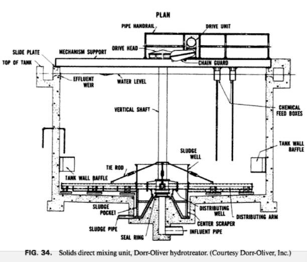
Figure 34 shows an older design using the same principle. New feed (plus flocculants and/or reactants) is introduced through orifices along hollow arms rotating below the top of a “sludge blanket.” It was originally conceived that the new- feed would be “filtered” through the sludge blanket, and in a loose sort of way it may be so explained, but if the new feed were not dispersed and locally mixed into the sludge blanket, it would channel to the top in low- density currents. So the mechanism is probably just recirculation and mixing of sludge solids into the various feed streams to bring them into the line settling regime.
The internal sludge recirculation schemes embodied in the designs discussed above tend not to break down floccules existing in the settled sludges. The one shown in Fig. 32 particularly points topologically and conceptually to external recirculation types. A suitable fraction of the underflow stream is diverted into an external mixing chamber and/or flocculation compartment where it is mixed with new feed. Mixed feed then flows to a settling unit of conventional configuration. The hydrodynamically rough handling of the underflow stream undoubtedly damages the existing floe structure. Where the mixed feed reflocculates quickly enough to avoid segregation of fines in the feed zone, external recirculation should accomplish much of what internal circulation does, with less cumbersome mechanical configurations.
Selective Recirculation Thickeners
In some operations, thickener underflow is sent on to further processing, from which a certain amount of solids are returned to the thickener. Obviously such recycling increases the load on the thickener.
The increase is usually insignificant, but if the subsequent processing selectively returns fines, an augmented recirculating load of fines will form. This condition arises most often when thickener underflow is sent for further dewatering to a device which acts as a classifier. A solid-bowl centrifuge, for example, acts in almost all cases as a classifier, in that coarse solids segregate to some degree from fines in the machine, and the fines report selectively to the overflow. If the centrifuge overflow is then recycled to thickener feed, the recirculating load of fines which forms may in some cases become large enough to overload the thickener. (This has happened a number of times in industrial practice.) So if the use of a solid-bowl centrifuge or any other classifying device is being considered for dewatering thickener underflow, or if there is selective recycle of solids to the thickener from any process source, a detailed material balance for all solids size fractions should be calculated to determine what the steady-state operating conditions will be.
