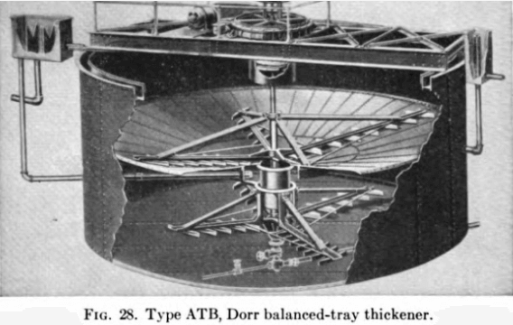
The diaphragm Thickener Underflow Pump is essentially one for low lifts and is particularly adapted to handle metallurgical pulps economically and with minimum attention. The Dorrco diaphragm pump was developed primarily as a means of controlling the density of the underflow from the Dorr thickener in the first continuous treatment of cyanide pulps. It has been proved the most satisfactory method of accomplishing this because of its positive, uniform displacement, which can be regulated at any rate of flow within the limits of its capacity. When the underflow from the thickener is too thin, a simple regulation of the pump will decrease the rate of discharge until its density is correct. Once the pump has been regulated, it is seldom necessary to change the adjustment unless there is a decided change in the feed to the thickener. Cord diaphragms constructed on the same principle as cord tires give appreciably longer life than the original fabric construction. Diaphragm pumps of different types are available from several manufacturers.
The diaphragm pump has on various occasions been challenged by the centrifugal pump, but the characteristics of the former as mentioned above show advantages in its favor. When a thickener becomes overloaded, the centrifugal pump tends to “pack up” and remove less pulp; the diaphragm pump increases its delivery in terms of solids and so tends to compensate the overload condition. On the other hand, the centrifugal increases its output as pulp density decreases and this is obviously undesirable.
Describing the history of the diaphragm pump, Luther B. Eames, well- known engineer and an early associate, writes:
To our knowledge the earliest use of the diaphragm pump in metallurgical plants was for recirculating pulp in the loading tank of a Moore filter at the Lundberg, Dorr, and Wilson mill at Terry, S.D. This was of the type sometimes called a pitcher pump. It had flap-type valves which, however, caused irregular operation due to the presence of wood chips and tramp oversize in the pulps discharged from thickeners.
As a result, pumps were designed more suited to use in connection with thickeners. At the Hollinger mill valves were developed which discharged around the whole periphery of the valve seat and were so designed that the center of gravity of the valve was below the valve seat. Also seats and valve disks were of soft rubber so that any chips or tramp would not cause leakage and would be washed off the seat at the next stroke. This is of importance, particularly in countercurrent washing, where it is essential to keep the capacity of all pumps constant and equal.
Ball-type valves have also been used. The balls are of rubber weighted with steel cores and operate against circular rubber seats. This type, however, has been used more generally in the industrial than the metallurgical field.
Cyanidation and concentration of gold and silver ores
For more complete automatic control the set point of the flow-controlling loop can be governed by underflow density with an override to increase the underflow as rake torque rises. In the absence of automatic control coupling, the control loops are closed through the operators.
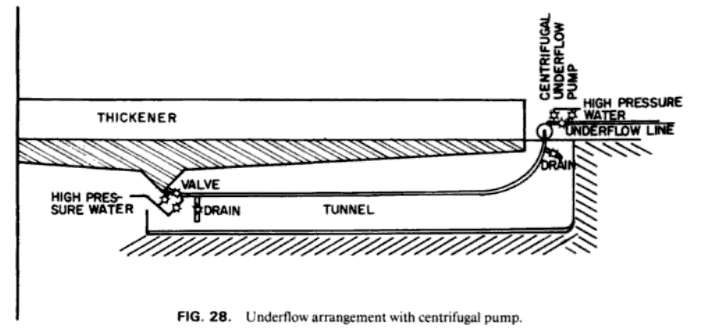
To avoid plugging of the underflow line, it is advantageous to make the section between thickener underflow and underflow pump suction as short and straight as possible, but this presents a problem. It is not good practice to install an electrically-driven pump in a pit under the thickener, so in many cases the pump is located at ground level alongside. Where it is evident that over-thickening will be severe, and particularly for segregating pulps containing a lot of sandy material, it is good practice to elevate the thickener so that the underflow pumps can be located under it. In at least one alumina plant the thickeners are carried on columns. In a nickel plant they are constructed on a fill. Underflows are into tunnels, open on both ends, passing under the thickeners.
In any case, underflow lines should be provided with high pressure water connections and with drains so that they can be flushed out when they become plugged. Means should also exist for adding a small stream of water (if the process permits) at the inlet end of the underflow line to dilute overthickened sludges to a more pumpable consistency. Actual arrangements will vary from case to case and from layout to layout. Figure 28 shows the sort of thing needed.
Unit Operations Handbook: Volume 2

