Table of Contents
The proper sampling of ore in the crushing section of a Laboratory Test Plant is very often a problem involving considerable handling and labor if the proper equipment is not available. Accuracy of the final sample, and therefore test results, may also be impaired if too much manual labor enters into the operation. It is generally agreed that the most accurate sampling is done by mechanical and automatic methods if the mechanical sampler is properly designed for the specific problem or operation.
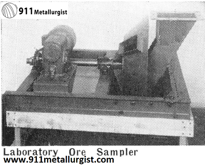
The Laboratory Ore Sampler is designed for sampling dry ore, preferably after crushing to three-eighths inch and finer. The sampler is of all-metal construction and, since its overall dimensions are small, it may be incorporated into the average laboratory crushing plant without difficulty. Feed enters the sampler and the cutter in pan number one cuts a 10% sample. This sample falls into the mixing barrel which is a part of the unit. It is then thoroughly mixed and discharged uniformly through pan number two. Here again a 10% sample is cut and rejects combine with those from pan number one. The final sample represents 1% of the original weight. This sampler also is available with a single cutter for making sample cuts of 10% where no smaller cut is desired or necessary.
The sampler is of unit construction and long, dependable service is assured by the simple, sturdy design. It may be used for accurately sampling small batches as well as tonnage lots of ore.


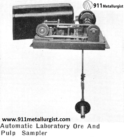
Automatic Laboratory Ore And Pulp Sampler
The Automatic Laboratory Ore And Pulp Sampler is excellent for checking the results made in Continuous Laboratory Test Plants. It can be moved easily from one part of the flowsheet to another, and operated from an ordinary electric light circuit.
This sampler is economical, having no expensive and complicated electrical devices to regulate the cutter. An ingenious reducer arrangement has been designed which immediately engages the cutter at the correct interval, and a synchronous motor gives electric clock precision. The entire unit is mounted on a welded steel base and is compact in design. Two types of cutters can be supplied—for horizontal or for vertical work.
The time intervals available between cuts are constant and can be set for 12, 8, 5.33, 4, 2.66, 2, or 1.5 minutes at 60 cycles and 14.4, 9.6, 6.4, 4.8, 3.2, 2.4, and 1.8 minutes at 50 cycles. Maximum length of travel of the cutter is 20 inches. Standard motor is 110 volt, 60 cycle, single phase, but motors of any current characteristics can be furnished. Belt drive machines are also available.
When ordering specify:
- Current;
- Sampling interval (minutes);
- Type of cutter, either horizontal or vertical blade;
- Whether material is wet or dry (if dry, the size of largest piece).


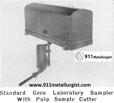
Ore and Pulp Laboratory Sampler
The Geco Automatic Sampler mechanism is designed to operate suitable sample cutters for the intermittent removal of accurate samples from streams of wet or dry materials at predetermined time intervals. The cutter is supported from the carrier block of the mechanism, and with the mechanism located in proper relationship to the stream of material to be sampled, the operation of the mechanism moves the cutter into and across the stream in a straight line and at a uniform speed. As it passes through the stream, the cutter is designed to deflect a representative portion of the stream into a suitable container. Three types of cutters are available to allow a selection to be made that will best satisfy the requirements of each installation.
The driving unit of the Geco Automatic Sampler mechanism is a gearmotor which operates only at intermittent periods, controlled by a time switch. A roller chain, driven by a sprocket wheel mounted on the gearmotor shaft, is carried over an idler sprocket wheel, which runs upon an axle supported by pedestal bearing which also provides for adjustable chain tension.
The sample cutter, suspended from the carrier block, is moved back and forth by the engagement of an extended pin connecting two links of the chain with the disengaging arms mounted on the carrier block. Cutter travel is adjustable from 16″ to 20″ in length as standard, but units with longer cutter travel are available.
The direction of the cutter travel is reversed, for each succeeding sample cut, through the opposite directions of travel the extended pin assumes in following the path of the chain travel over the sprockets.
At the limits of the carrier travel, energy to the motor is cut off by the opening of a limit switch and the carrier remains at rest until the circuit is restored by the time switch through the second limit switch at the opposite end of the carrier travel.


Automated Mineral Processing Plant Sampling
It is desirable that the discharge from the final classifiers should be sampled regularly as a check on the working of the grinding circuit. A sample so taken is also often the best method of determining the assay value of the ore feed to the plant, although it is usual to sample also the discharge from the final crushing machines which form the feed to the grinding section. These two samples are not normally of the same assay value day by day, but they should check closely over long periods the sampling has been properly carried out.
The figures are based on a pulp containing 25% solids of sp. gr. 3.0, 3% of which is plus 65 mesh.
The horse-power figures represent the actual power consumption, not motor sizes. The capacity figures represent the maximum delivery possible for a given head at the speed at which the greatest overall efficiency is developed.
In small plants sampling is often done by hand, but the method has obvious disadvantages and automatic sampling is much to be preferred. The main requirements of sampling, whether by hand or machine, may be summarized as follows :—
- The sampler should take the whole of the stream of ore or pulp part of the time.
- The sample cutter should travel at a uniform rate while passing through the stream.
- The sample cutter should move completely across and out of the stream at each cut.
- The interval between cuts should be constant.
- Cuts should be frequent enough to ensure a representative sample being taken.
- For automatic sampling the stream should be continuous.
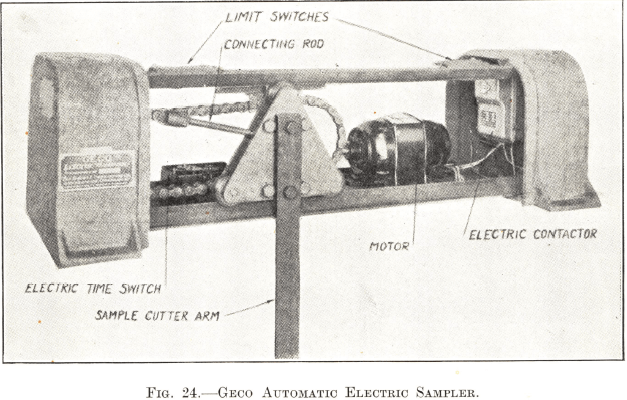
The Automatic Electric Sampler illustrated in Fig. 24 fulfils the above conditions and is representative of the type of machine used in modern practice. It consists essentially of a cutter arm driven by an electric motor at regular intervals which are controlled by a time switch.
The cutter is fixed to a carriage running on grooved wheels between two guide bars. It is operated by means of a connecting rod, one end of which is fixed to the carriage, while the other end is secured to one of the link pins of a driving chain. The chain is carried on two sprocket wheels ; one runs free and the other is driven by an electric motor through a flexible coupling and speed reducer. The free sprocket wheel is provided with an adjustable tension device.
The driving motor is started at predetermined intervals by an electric time switch, which is usually of the Baldor motor type. By the time the cutter is moving across the stream of ore or pulp, the driving motor is up to full speed, and it maintains its uniform rate of travel until the cutter has passed out of the stream, when it is stopped by one of the two limit switches, which are placed at each end of the top guide bar and actuated by contacts on the carriage. The operation is repeated after the next interval, the cutter passing across the stream in the opposite direction. The two-way travel of the cutter does not necessitate reversing the driving motor ; motor and chain travel in the same direction at each stroke.
The whole of the mechanism is normally encased in a water and dust-tight cover. The sampler is made in a range of sizes to give an effective cutter travel of from 18 to 39 in., but any length of travel can be supplied for special purposes.
