Table of Contents
Metallurgical Recovery, which consists of the percentage of mineral saved, must not be confused with economic recovery which covers the percentage of the gross value of an ore recovered as a net profit. In other words, in commercial practice the prime object is the highest possible net profit over and above all costs. Thus a lower metallurgical recovery with a higher net profit is much more desirable than a higher metallurgical recovery with reduced net profit or an actual loss.
Another factor affecting economic recovery is the proximity of the operation to a market thus determining the proportion of values in the product to be marketed. A mill may secure a low tailing and sacrifice possible additional net profit by paying freight on the useless material in a lower grade concentrate and in some cases a penalty on undesirable material to the smelter or refinery.
Modern flowsheets are steadily becoming more efficient through their greater simplicity. This is due to the increasing knowledge and understanding of metallurgical and economic factors affecting milling problems and the development of machines which easily give recoveries that in the past were considered to be impossible from a practical point of view.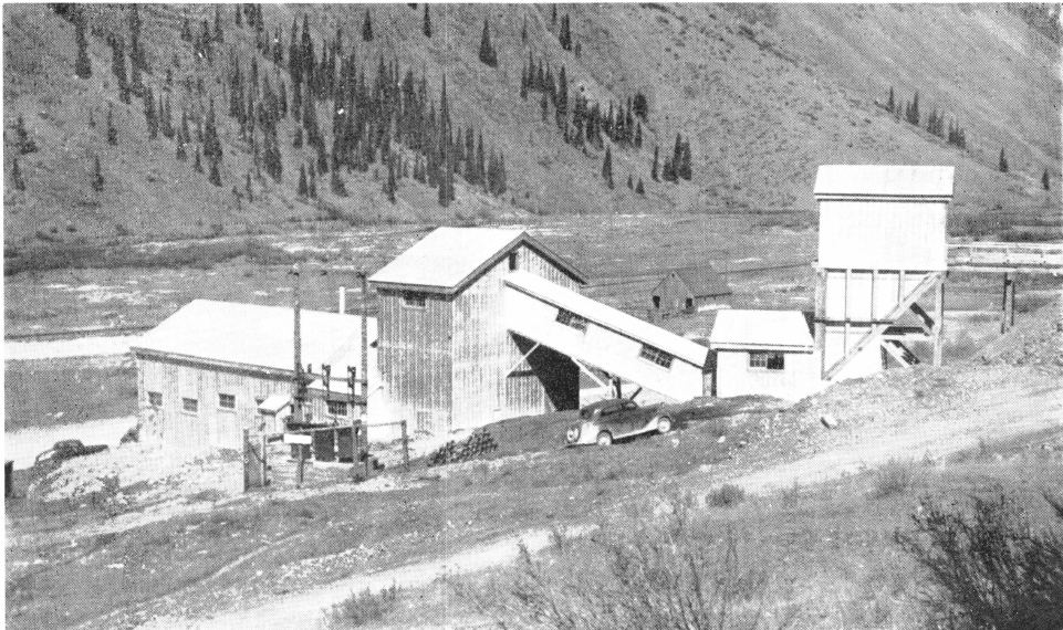
An outstanding example of this is the reduction of the amount of troublesome middling product and the avoiding of the colloiding of the mineral particles due to overgrinding by the use of the Mineral Jig and the Unit Flotation Cell in the grinding circuit. These two machines mark a distinct advance in modern metallurgy recovering the mineral as soon and as coarse as possible in a high grade product with resulting lowered milling costs and higher recoveries.
Where it is impossible to use both of these machines in series in the grinding circuit, in nearly every instance it pays to use either the Mineral Jig or the Unit Flotation Cell. The Unit Flotation Cell, with its distinct circulation by gravity and use of rubber parts, has made the floating of the coarse mineral in the ball mill-classifier circuit possible and profitable. Likewise, the production of a high grade selective concentrate and the low water requirements of the Mineral Jig make possible and desirable its use in this same circuit.
THE PRIDE MILL is an efficient and modern milling plant, incorporating the latest and most up- to-date principles of ore dressing. In this plant have been included all features that will insure maximum metallurgical efficiency without sacrifice in cost.
The most important feature adhered to in this mill is the correction of the “middling problem” which has been solved by the use of a Unit Flotation Cell and Mineral Jig in the grinding circuit, thereby recovering most of the valuable minerals as coarse and as soon as possible.
The “curse of modern milling” overgrinding everything to correct the middling problem has been eliminated. This is accomplished by the removal of free mineral in the grinding circuit with the Jig or Unit Cell, which also eliminate the circulating load of free mineral. Free mineral that is too heavy, due to specific gravity, to overflow the classifier is also removed from the grinding circuit by this method.
The Mineral Jig and The Unit Flotation Cell in the grinding circuit perform two important and separate functions. In grinding mill discharge there may be two types of minerals, one requiring gravity methods of concentration and the other flotation. The Mineral Jig removes heavy mineral (both coarse and fine) where floatability is negligible due to size and specific gravity. The Unit Cell removes floatable mineral as soon as free, and in addition produces a high grade selective concentrate containing both coarse and fine floatable minerals.
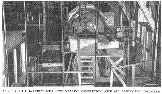
The Pride Mill is treating well over 50 tons a day of lead- zinc ore with values in gold and silver. In addition to the correction of the “middling problem” several other unique features are incorporated.
The Mineral Jig and The Unit Flotation Cell in the grinding circuit prevent mineral colloiding, thus insuring a high overall recovery with a final product which is coarse and relatively slime free, highest in grade, easily filtered and dried. The coarse granular Jig and Unit Cell concentrates, as well as the final lead and zinc flotation concentrates, are elevated with Vertical Sand Pumps to the concentrate filter.
All pulp flows are by gravity and mill control is simplified by accurate density regulation. Mill washings pass by gravity to one sump.
The handling of reagents requires a minimum of attention on account of the facilities for mixing and feeding.
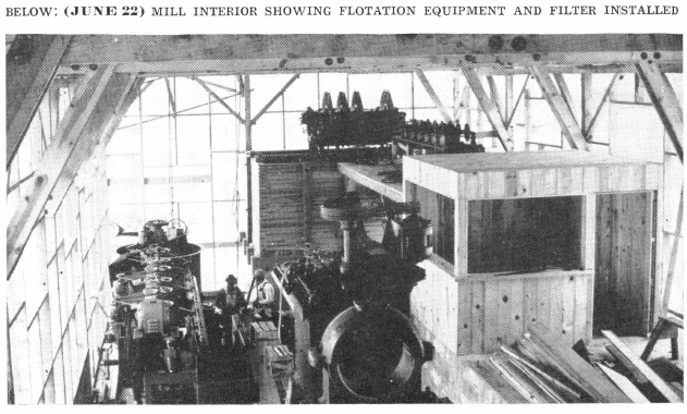
Fluorescent lights in the mill, and particularly over the flotation sections, greatly improve the visual observation of the products. These are visible from the mill office, centrally located, so that all operating equipment can be seen from an observation platform.
These features, along with several others and the metallurgy, are detailed in the following article.
Mineral Processing Plant Location
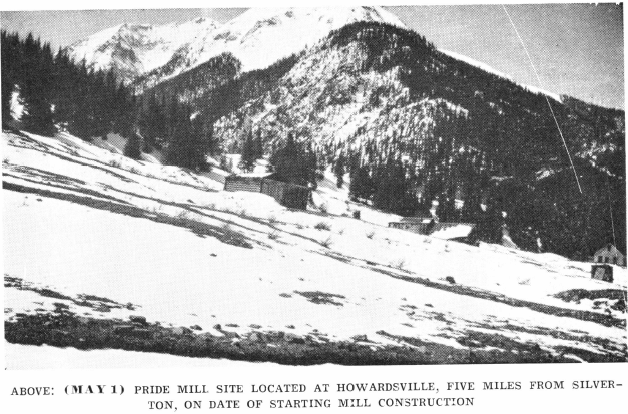
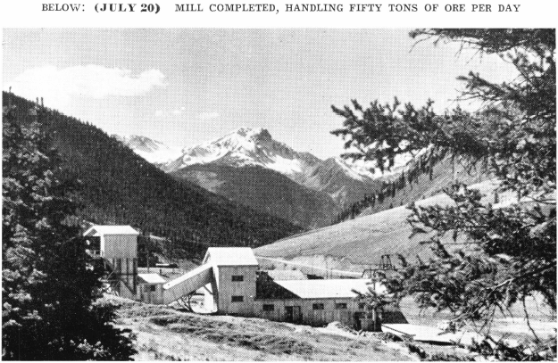
The Pride of the West Mill and Mine are located in the San Juan District of Colorado. The Mill is situated at Howardsville, at the junction of Cunningham Creek and the Animas River.
Howardsville, at an elevation of 9,600 feet, is five miles from Silverton, the centre of the district. Howardsville was the original capitol of this section. It dates back to the 1870’s.
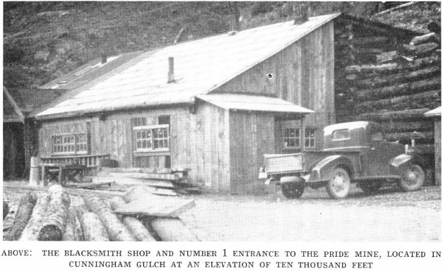
This 50-ton mill treats ore from the Pride of the West Mine which is some two miles distant, up Cunningham Gulch, at an elevation of 10,000 feet. The Pride of the West claim, bearing No. 42, was patented in 1870, and is, therefore, one of the earliest claims staked in the San Juan District of Colorado. The mine is developed by three tunnels, and over 6,000 feet of workings.
Ore
Mine ore consists of fissure vein material in andesite. Ore minerals are galena, tetrahedrite, chalcopyrite, pyrite, and sphalerite. Gold and silver values occur partially free, and the balance associated with the galena. High silver values are related with the tetrahedrite. The gangue material is quartz with small amounts of calcite and altered andesite. Most of the pyrite occurs in vein walls and is relatively free of gold and silver.
Power
Power is obtained from the Western Colorado Power Company, and it is brought in at 17,000 volts and stepped down to 440/220 and 110 volts. The approximate cost is $6.50 per peak load horsepower each month. The wiring in the mill is all oversize in conduit to reduce heating losses with subsequent lowering of power costs. It is estimated that the additional wiring installation cost was paid for after three months operation, due to the elimination to a great extent of the live heat losses. The peak load at the mill with the crusher running is 126 Hp., with a feed rate of 50 tons per day. All mill equipment is motor driven through “V” to “V” drives except the ball mill which has a “V” to flat drive. The mill reset magnetic switches are away from dust and dirt on an upper platform in the roof trusses above all equipment. Machine control is through a switch panel located in the mill office with auxiliary starting equipment at the several units. The mill is well lighted by modern fluorescent lights.
Water
Mill water supply is obtained from Cunningham Creek and pumped into a storage tank at 60 gallons per minute against a 100-foot head. Water is pumped into the tank and discharges at the top through a “V” weir in the pipe line. This arrangement avoids splash and surging and subsequent icing troubles in winter months.
The storage tank consists of an 8′ x 8′ Bolted Steel tank set in a 10’x 10′ wood tank; it is high enough above the mill for adequate fire protection. The intervening space between the tanks is insulated. A three-way plug cock controls the flow on the discharge line to the mill. The pump is a 1¼” Centrifugal Water Pump powered with a 5- Hp. motor. The pump is set vertically on the concrete pump house wall and with a 3-foot head from the creek intake above the pump, this unit is always primed. The plug cock on the pump intake drains both pump, intake, and discharge line.
The main water line into the mill and all lines to each machine requiring water are controlled by two plug cocks. The first plug cock is available for shutting off the water in that line while the second plug cock controls the flow to the particular unit. This arrangement allows the water to be shut off on any unit without disturbing the adjustment to that machine. This has proved a very useful arrangement in maintaining accurate densities which are important in selective circuits. The main line to the mill is also arranged in this manner which allows shutting off mill water at one place instead of at various places in mill.
Milling
CRUSHING
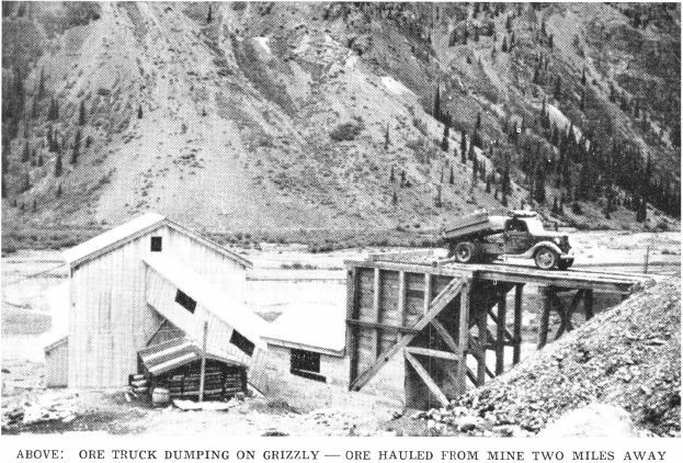
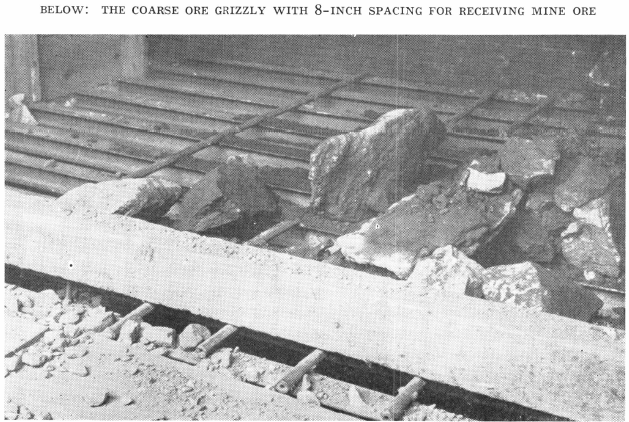
Ore is transported from the mine in a truck with a five-ton capacity, a distance of two miles. This truck works under contract about nine hours a day. The same truck hauls the concentrates to Silverton in bulk. Mine ore is dumped directly from a ramp onto the coarse grizzly which is made up of heavy rails with 8″ spacing. Oversize is bulldozed through the grizzly where it joins the undersize in the coarse ore bin which has a live capacity of 50 tons.
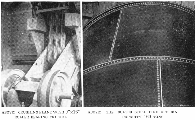
The coarse ore passes over a 5’x 2′ wide 1¼” grizzly ahead of the crusher. Grizzly undersize passes direct to the conveyor belt, while the oversize to the crusher is controlled by a No. 3 Ross Chain Feeder which has a capacity of 9 tons per hour. This feeder is powered with a ½-Hp. gearmotor. The crusher consists of a 9″ x 16″ anti-friction bearing jaw crusher powered with a 10-Hp. totally enclosed fan-cooled ball bearing motor. The jaw opening is maintained at 1″.
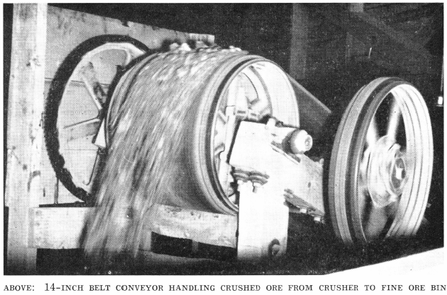
The crusher discharge, along with the grizzly undersize, is transported on a 14″ x 65′ conveyor with a slope of 4 3/8″ per foot at 150 feet per minute to the fine ore bin. The conveyor is powered with a 2-Hp., 1200-r.p.m., fan-cooled, totally enclosed ball bearing motor. The drive is “V” to flat through gears to the main conveyor pulley.
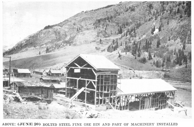
The bin is a 15′-4½”x 16′-1″ Bolted Steel Tank with a capacity at 120 pounds per cubic foot of 160 tons.
The crushing section operates one eight-hour shift per twenty-four hours with one man looking after the bulldozing, crusher, and conveyor equipment.
GRINDING CIRCUIT
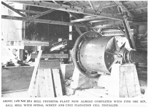
A 16″ x 14′ 3″ Inclined Belt Ore Feeder with a slope of 3″ per foot moves the feed to the ball mill. This feeder is set directly under the hopper which is in the center of the bin. The hopper is so constructed that the weight of the feed discharging from the bin is not on the belt, but on the slope of the hopper. The movement of the belt pulls the material from the hopper into a compartment where the feed onto the belt is controlled by an adjustable restriction plate.
The ore feeder is of the troughing type and is powered with a 1-Hp. Reeves No. 25, 50 to 1 Reducer Drive through chain and sprocket. The belt travels at approximately 10 feet per minute.
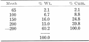
Feed to the grinding circuit has the following screen analysis, which assays:
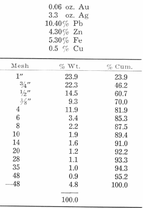
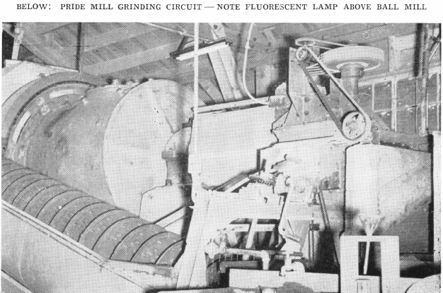
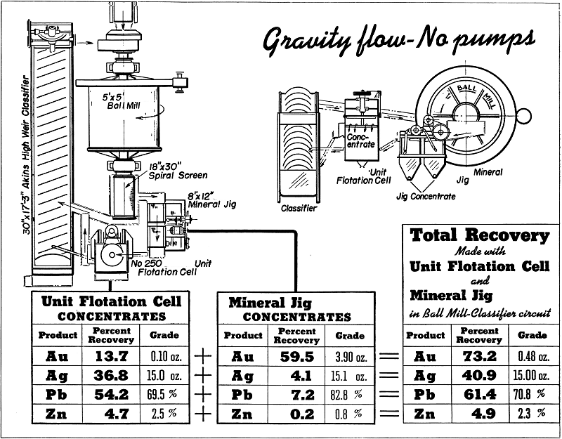
The grinding mill is a 5′ x 5′ left-hand Type “B” steel-head Ball Mill with a right-hand “V” to flat drive on the feed end of the mill. The ball mill is powered with a 50-Hp., 900-r.p.m., 440- volt Westinghouse Synchronous Motor. The mill r.p.m. is 25.3 and is started by a Westinghouse De-Ion Linestarter. The unit is equipped with a combination scoop feeder which has a Decolloy wear resisting scoop lip. Shell liners are manganese steel and end liners are Decolloy. On the discharge end of the mill is an 18″ x 30″ Spiral Screen with 0.13 opening with 0.092 wire. The mill discharges at 70% solids with the spiral screen oversize returning to the classifier and the undersize to an 8″ x 12″ Duplex Mineral Jig.
The screen analysis of spiral screen oversize and undersize Jig feed, is:
The Jig tailing flows by gravity to a No. 250 left-hand Unit Flotation Cell with Unit Cell tailing and Unit Cell sand discharge flowing to the classifier.
The classifier which closes this grinding circuit is an Akins 30″ Simplex high weir unit with a right-hand feed and a left-hand drive. The slope is four inches and the spiral operates at 8 r.p.m. The classifier is powered with a 2-Hp., 1200-r.p.m. motor through “V” to “V” drive. A Boston ¼-Hp., single-phase, 110-volt Ratiomotor on the classifier discharge end activates a paddle which keeps wood pulp off the classifier overflow screen.
The classifier sand return to the grinding mill has the following analysis:
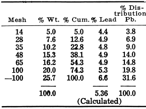
Classifier Return Assay: 0.07 oz. Au; 2.75 oz. Ag; 5.05% Pb; 4.90% Zn; 7.00% Fe.
Make up water and lead flotation reagents are added to the classifier sands. A water spray is maintained on the ball mill spiral screen and this, in addition to keeping the screen clean, washes the oversize material down the launder to the classifier. This launder, along with the Unit Cell tailing launder and the launder for the classifier sands, is made up of angle iron. This has been found quite advantageous in cutting down the amount of water required for the grinding circuit, allowing it to be added at one point, thus maintaining accurate density.
MINERAL JIG
The Mineral Jig in the grinding circuit is arranged so that a hutch product may be pulled from either one or two compartments, depending on the nature of the feed and the tonnage. The Jig is producing approximately 900 pounds of concentrates per day. These concentrates have an average assay of 3.9 oz. Au, 15.1 oz. Ag, 82.8% Rb, 0.8% Zn, 1.5% Fe, 1.1% Insol., 0.4% Cu, and a screen analysis as follows:
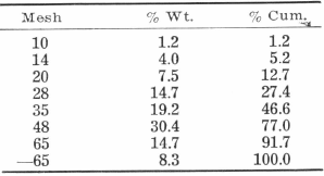
This coarse granular material is sent direct to a drain box. It flows by gravity from the hutch into the bowl of a 1½” Vertical Sand Pump and is elevated 18 feet to a drain box where it can be shipped either as a separate product or mixed with the lead flotation concentrate.
The stroke on the Mineral Jig is changed from time to time to suit mill conditions. The lower wedge wire screens have a 2 mm. opening and support a 1″ bed of 3/16″ steel shot. A natural bed of sulphides is over the shot. The hutches are pulled at two hour intervals. The water to the Jig is maintained at a constant amount and this insures an even grade of Jig product. It also affords a point of entry of dilution water to the grinding circuit. This addition of water in the Jig is just sufficient for the proper dilution in the Unit Cell. The Jig is powered with a 1-Hp. motor through “V” to “V” drive.
On some ores a cleaner Mineral Jig makes a higher grade concentrate with the possibility of amalgamating the gold values.
FLASH FLOTATION CELL
The No. 250 Unit Flotation Cell is powered with a 5-Hp. motor through “V” to “V” drive. With weir block control, the pulp level is maintained at constant height and the Unit Cell produces around 4 tons of concentrates per day. These concentrates have an assay of 0.10 oz. Au, 15.0 oz Ag, 69.5% Pb, 2.5% Zn, 7.8% Fe, 6.3% Insol., and a screen analysis of:
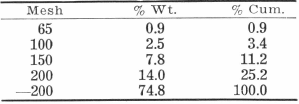
The concentrates flow by gravity and join the final concentrates from the lead section to a 1½” Vertical Sand Pump which lifts them a vertical distance of 18 feet to the filter. The Unit Cell sand relief, instead of passing vertically to the weir overflow, discharges through a horizontal 1½” line directly to the classifier. This line constantly relieves the oversize from the Unit Cell and thereby reduces to a minimum, wear on the molded rubber impeller.
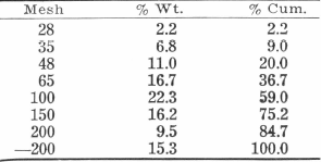
The tailing from the Unit Flotation Cell has the following average screen analysis:
LEAD FLOTATION
Due to the small amount of water used by the Mineral Jig and the Unit Flotation Cell, the classifier overflow density can be maintained at 34% solids. This pulp has an average assay of 0.02 oz. Au, 2.1 oz. Ag, 4.3% Pb, 4.6% Zn, and a screen analysis of:
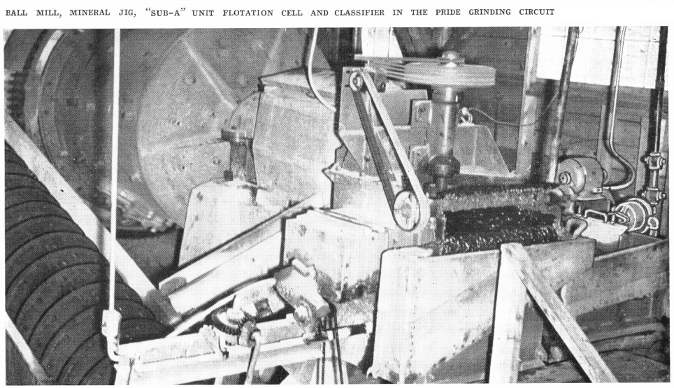
The overflow is by gravity to the No. 2 cell of the 6-cell No. 18 (28″x 28″) left- hand “Sub-A” Flotation Machine which constitutes the lead section. This machine is powered with three 2-Hp. motors through “V” to “V” drive. Each cell is equipped with the new receded disk impellers and diffusers which give maximum aeration with finely divided air. The cells have handwheel operated gates for cell to cell pulp level control.
The rougher concentrates from cells 3 to 6 flow by gravity to No. 2 cell along with the original feed. The cleaner concentrates from No. 2 cell flow by gravity to No. 1 cell where the recleaner final lead concentrate is produced. These concentrates join the Unit Flotation Cell concentrate, as previously described. The cell to cell type of construction of the Flotation Cells makes the maximum flexibility possible.

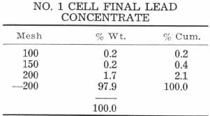
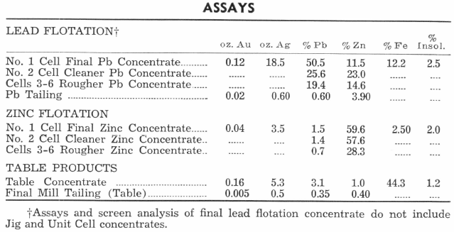
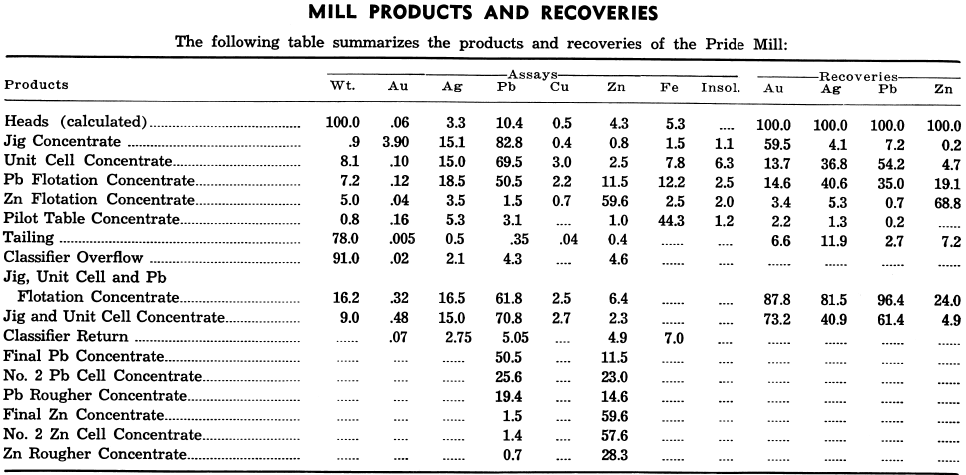
The average assay of lead products is shown in the assays table. Screen analysis of concentrate is as follows:
ZINC CONDITIONER
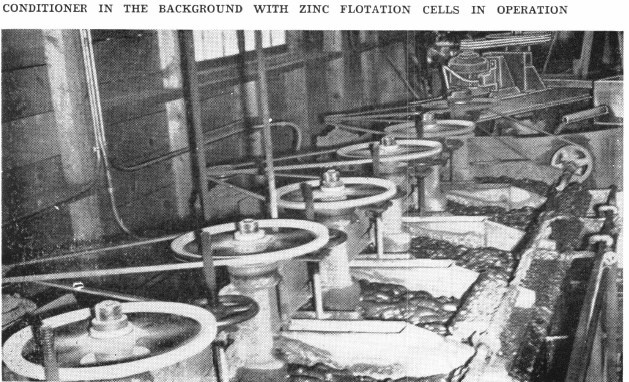
The lead tailing flows by gravity to a 6′ x 6′ Low head Conditioner. This conditioner is powered with a 3- Hp. motor through “V” to “V” drive. The unit is equipped with a rubber covered propeller. The conditioner discharges from a 3″ pipe near the top of pulp level of the conditioner; this pipe extends down to propeller level and takes both sand and slime from conditioner without necessity of separate sand relief pipe. The feed intake to this Conditioner is immediately above propeller and head is gained through conditioner thereby allowing lead and zinc machines to be set on the same level without the use of any pumps. The zinc reagents are added to the conditioner, and with a density of 25% solids, there is a maximum contact period of forty minutes.
The discharge arrangement on this conditioner is important to counteract any tendency to sanding and an even discharge of both sandy and slimy material is assured.
ZINC FLOTATION
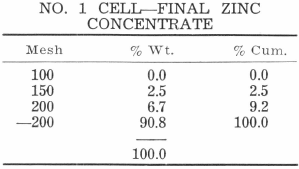
The zinc machine is a duplicate of the lead machine, being a 6-cell No. 18 (28″ x 28″) “Sub-A” left-hand Flotation Machine with new receded disk impellers and diffusers, and handwheel weir gate control. The zinc conditioner discharges to the No. 2 cell with rougher zinc concentrate from cell 3 to 6 flowing by gravity to the No. 2 cell. The cleaner concentrate from No. 2 cell flows by gravity to No. 1 cell for production of final zinc concentrate amounting to 2.5 tons per day. averaging 59% zinc. This concentrate flows by gravity to a 1½” Vertical Sand Pump for elevating 18 feet to the zinc section of the filter. The zinc products assay is shown in the assays table and screen analysis is as follows:
PILOT SHAKER TABLE
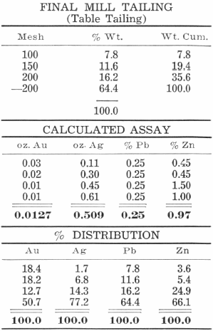
The zinc tailing, at a density of 20% solids, is sampled by a 3″ automatic sampler, equipped with a Thruster, and passed to a No. 12 left-hand Wilfley Concentrating Table where an iron-lead concentrate amounting to 50 pounds per day is produced. This pilot table indicates visually the work being done by flotation immediately preceding.
Table tailing flows by gravity to the tailing disposal pond below the mill. The table concentrate joins the lead concentrate for shipment to the smelter. This table is a motor “V” drive type with a 1½-Hp. motor. Table products assay is shown in the assays table, and screen analysis of table tailing, calculated assay and percent distribution are as follows:
FLOTATION REAGENTS
Reagents are mixed in three 55-gallon drums on the reagent floor at the head of the mill. Cyanide is made up in a 30-pound batch, zinc sulphate in a 60- pound batch, and Xanthate in a 15- pound batch. Sufficient water for the charge is added to the drum, then the reagent. Each mixing barrel is connected with a Gould ¼-Hp. direct connected all-iron ¾” solution pump. These pump motors are single-phase, 110-volt. The pumps handle the mixture from the bottom of the barrel to the top, thereby insuring a thorough mixing action. This mixing is allowed to take place for an hour or two, then the plug cock from the pump to the mixing barrel is closed and the plug cock on the line to the reagent storage barrel is opened. The pump then elevates the reagent from the mixing barrel to the storage barrel located on the upper reagent floor. There is no danger of this storage barrel overflowing as there is an overflow line back to the mixing barrel on the lower floor.
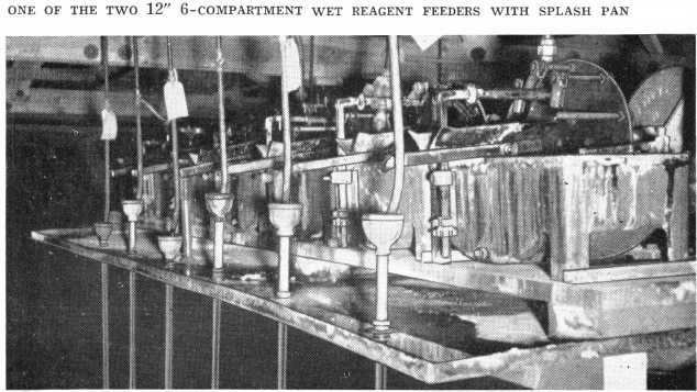
Reagents from the storage barrels flow by gravity to the correct compartment of the two 12″ 6-compartment Wet Reagent Feeders. One 6- compartment wet reagent feeder is located at the head of the grinding circuit for the lead reagents. The other 6-compartment wet reagent feeder is located above the zinc flotation circuit. The reagent flow from the feeders is by gravity to the point of addition.
REAGENT FEEDERS
Each Wet Reagent Feeder is powered with a ½-Hp., single-phase, 110/220-volt motor through “V” to “V” drive.
The Wet Reagent Feeders are placed on a sheet steel pan with a depth of one inch. Each pan slopes to a drain to handle all reagent spills by gravity to the tailing disposal launder. This arrangement eliminates drip and spill which is usual under reagent feeders.
The reagent lines to the machines carry a sufficient amount of water to prevent plug-ups.
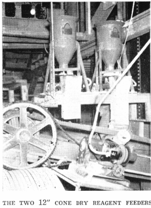
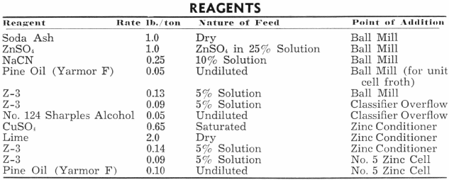
Soda ash is fed dry to the ball mill feed belt by means of 12″ Cone Dry Reagent Feeders with ¼-Hp. drive; the cone dry reagent feeders are in duplicate. Lime is fed dry to the Zinc Conditioner by means of a 6″ x 6″ Belt Dry Reagent Feeder. This feeder is powered by ¼-Hp. motor which is single-phase, 110-volt. The above table summarizes the reagents used in this plant, giving the rate in pounds per ton, nature of feeding, and point of addition.
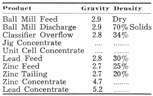
The pH of the classifier overflow is maintained at 8.4 and the zinc tailing between 9.7 and 10.0.
The following table gives the nature of the tonnage of the pulp in the various circuits:
CONCENTRATE DEWATERING
The lead concentrates which combine the Mineral Jig hutch product, the Unit Flotation Cell concentrate, and the lead section final concentrate are pumped to two sections of a 4′ diameter by 4-disc American right- hand filter which is powered by a ¾- Hp. three-phase gearmotor with a 49- r.p.m. output. This unit is operated to make one revolution in 245 seconds.
The zinc concentrates are pumped to one section of the disc filter leaving one section as a spare in case of emergency. This filter unit has a 9½” x 8″ vacuum pump with a forced feed lubricator. The unit is powered with a 7½-Hp. three- phase motor. A vacuum of 18″ is maintained. The air receiver is a 3′ x 5½” steel tank. The filtrate pump with 1/3 – Hp. single-phase motor handles the filtrate to the zinc conditioner. This filtrate feeds to a box at the conditioner so that the operator may note the clarity of the solution. In this way, a constant check is maintained on the condition of the filter cloth. This filtrate pump handles the filtrate from both lead and zinc sections of the filter. This also insures a closed circuit and automatic sampling of everything going out of the mill.
Thickeners have been eliminated in this plant by the use of Vertical Sand Pumps and filtering direct in the disc filter. The pumps elevate the products as formed without the addition of dilution water, thus a fairly high density is maintained in the filter.
Due to the ability of these pumps to handle both coarse and frothy material, thickening is not required.
FROTH PUMPS
Four 1½” Vertical Centrifugal Sand Pumps are used in this plant. Three of them are used in handling concentrates, while the other acts as the sump pump. All pumps are identical, hence parts are interchangeable. The 1½” discharge lines are bushed to ¾” which facilitates the easy handling of coarse granular concentrates with a small volume to maintain the discharge velocity. The pumps lift the concentrates a vertical distance of 18 feet.
MOTORS
The flotation machine motors, conditioner motor, and all of the pump motors are identical as to electrical characteristics and frame number. The motors are therefore interchangeable, and one spare motor is carried for any emergency.
All other motors in the mill are of standard manufacture. Where necessary, they are splash proof or totally enclosed type for protection from water and dust.
METALLURGICAL SAMPLING
Head Sample: The head sample is taken at the belt feeder discharge to the ball mill. This sample is taken with an especially constructed box which fits exactly to the feeder discharge. A telechron clock is located above the belt. This clock has a full face second hand so the operator has no difficulty in obtaining an exact sample. The moisture determination is made from this sample and it is then assayed for gold, silver, lead, and zinc.
Tailing Sample: An automatic sampler cuts the tailing of the zinc flotation machine and these samples are assayed on a shift basis for gold, silver, lead, and zinc.
Concentrates: Grab samples of the lead and zinc concentrates are taken at the filter and assayed for lead and zinc. Periodic samples are taken of the jig concentrates and unit cell concentrates. Control over these products is maintained through the final lead concentrate.

METALLURGICAL Laboratory
The mill laboratory contains a Pulp Density Balance, “Sub-A” Laboratory Batch Flotation Cell, Laboratory Drier, and a 12″ Laboratory Filter. A set of Tyler Screens are at hand for routine screen analysis. A LaMotte pH Block Comparator is used to control the alkalinity of the mill products. Reagents and samples are weighed on a Mill Utility Scale.
Mill Building
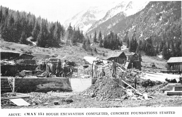
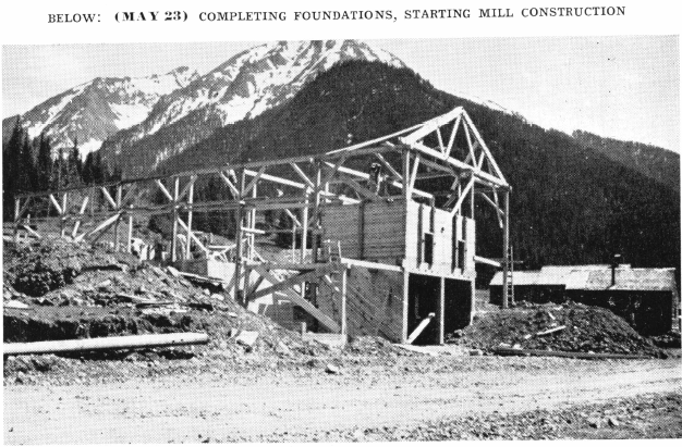
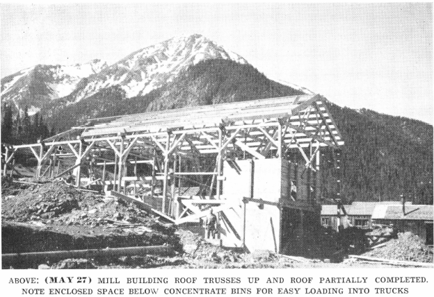
The mill is built on concrete foundations with a concrete floor draining to a concrete sump. The building is of wood construction with laminated wood trusses with one-quarter pitch. The siding is covered by insulation over which the outside surface is of copper bearing galvanized sheet steel.
The plant is heated with a Red Top B12 “Capital” steam boiler manufactured by the U. S. Radiator Corporation. The unit is serviced with an Iron Fireman Automatic Stoker. Two Stilphen Fan Heaters, powered with ¼-Hp. motors radiate the heat in the mill.
The total mill costs amount to $1.75 per ton of ore treated.
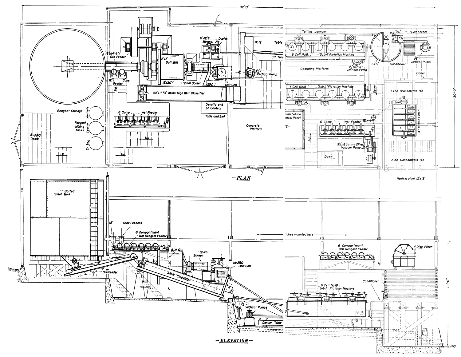
This mill was designed and built by the Equipment Company who furnished all standard equipment. The flowsheet, plan, and elevation of the mill give details as to its layout and these show the modern features that have been incorporated.
Previous to the erection of this plant, batch test work on the ore was conducted in the laboratories of the Equipment Company. Following the batch work, it was decided that a continuous test should be conducted to accurately determine the metallurgical results that could be expected, and also the details of the final flowsheet. Continuous tests were run using a feed rate of 200 pounds per hour. This continuous test was based on the batch results and reagent amounts, pulp flows, and conditioning periods were accurately determined. The sizes of equipment were then decided upon, based on the results of the continuous test.
The metallurgical results that have since been obtained in the operating plant, which is an exact counterpart of the continuous test plant, have verified the importance of testing the ore prior to the plant erection. The commercial unit has operated mechanically 100% of the time since the beginning of operations with equal or better results than those obtained in the test plant. The type of batch and continuous test equipment was identical to large scale commercial units, thus giving comparative results.
The Pride Mill clearly shows the importance of standard machines, each of the proper size and type, with emphasis placed on the important rule: “A Mill is as strong as its weakest link .”
Source: This article is a reproduction of an excerpt of “In the Public Domain” documents held in 911Metallurgy Corp’s private library.

