Vibrating Screen SPECIFICATIONS
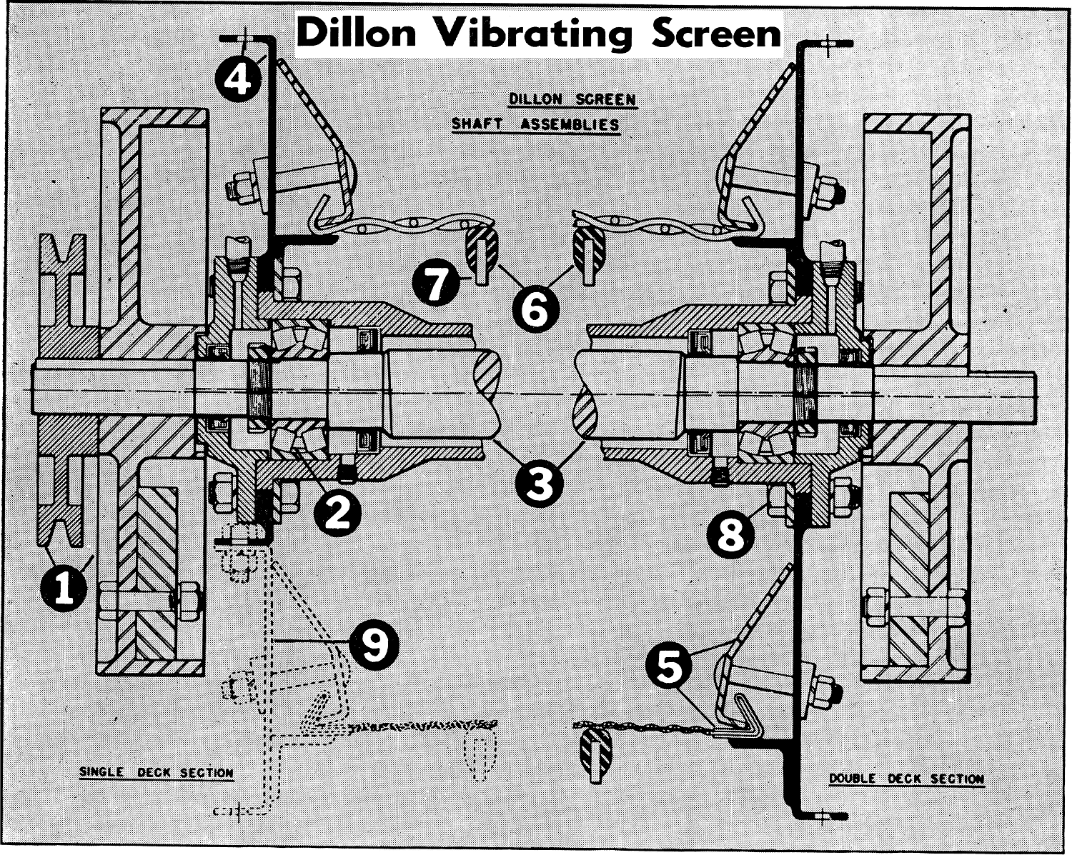
- The driven sheave and balance wheels are on the center line of the shaft. The shaft supports no other load and is subjected to no flexing or bending, and rotates freely on its central axis. The driven sheave can be mounted on either end of the shaft depending on whether a right or a left hand drive is desired.
- Only two heavy duty anti-friction bearings are required on the Dillon Screen. Pressure lubrication to center gives complete flushing. Grease seals keep dirt and moisture out of bearings.
- The demountable assembly may be completely removed from either side. The entire screen body gyrates positively and uniformly in a full circle, the radius being equal to the shaft eccentricity.
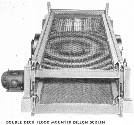
- The heavy gauge side plates are flanged for additional strength and rigidity. The flanges contain punched bolt holes, accurately lined up for attaching additional screen decks, dust covers, and discharge hoppers.
- Tension readily maintained on quickly replaceable screen sections. The formed angle plates holding the screen securely in position are fastened by standard carriage bolts. The tension mechanism design is dependent on the diameter of the wire in the screen used.
- Rubber-cushioned camber bars arch the screen section and prevent whipping and undue vibration.
- Deep section, full wedged deck panels accurately space and box-brace the side plates.
- Entire assembly securely locked with tightly fitting S.A.E. machine bolts.
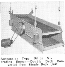
- A second and third deck can be conveniently added to a first deck in the field, or a third deck can easily be added to a double deck unit in the field.
Floating Circle Motion
What It Is
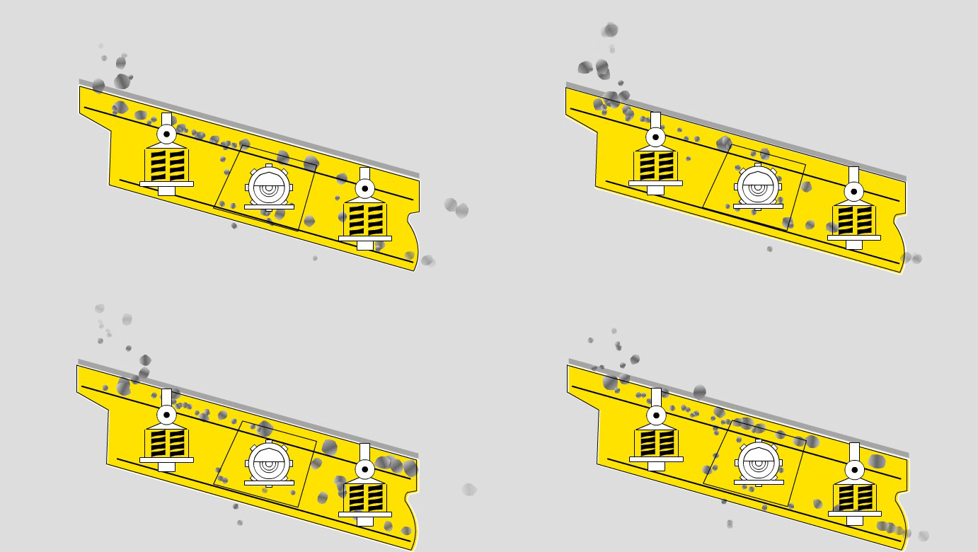
An extremely simple, positive method of imparting uniform “vibration” to the screen body. Using only two bearings and with no dead weight supported by them, the shaft is in effect “floating” on the two heavy-duty bearings.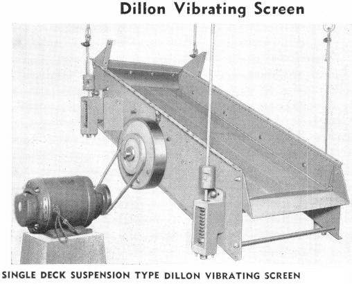
How It Works
The unit consists of the freely suspended screen body and a shaft assembly carried by the screen body. Near each end of the shaft, an eccentric portion is turned. The shaft is counterbalanced, by weighted fly-wheels, against the weight of the screen and loads that may be superimposed on it. When the shaft rotates, eccentric motion is transmitted from the eccentric portions, through the two bearings, to the screen frame.
The patented design of Dillon Vibrating Screens requires just two bearings instead of the four used in ordinary mechanical screens, resulting in simplicity of construction which cuts power cost in half for any screening job; reduces operating and maintenance costs.
With this simplified, lighter weight construction all power is put to useful work thus, the screen can operate at higher speeds when desired, giving greater screening capacity at lower power cost.
The “sting” of the positive, high speed vibration eliminates blinding of screen openings.
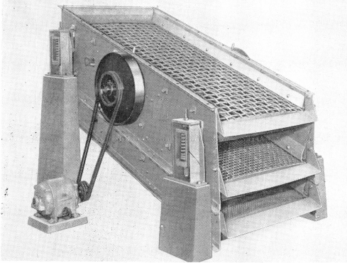
ILLUSTRATION AT LEFT TRIPLE DECK CONVERTED FROM DOUBLE DECK DILLON SCREEN
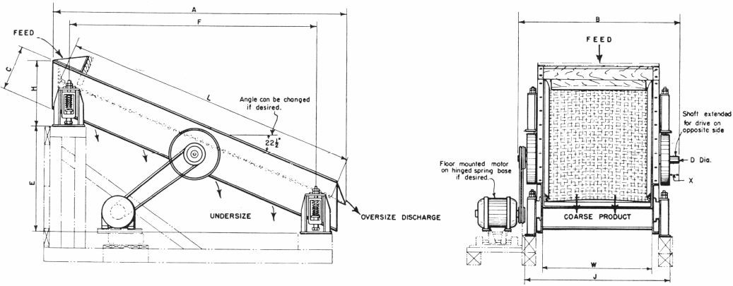
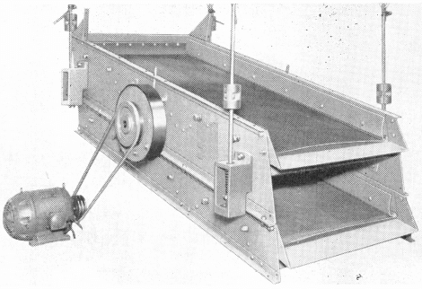
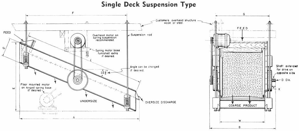
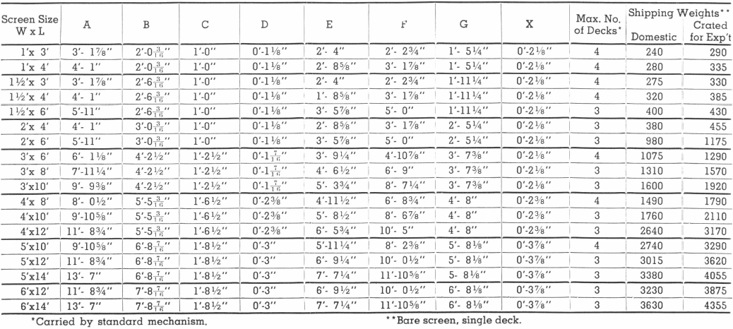
Double Deck Converted From Single Deck—Suspension Type
Methods of Fastening Vibrating Screen Cloth
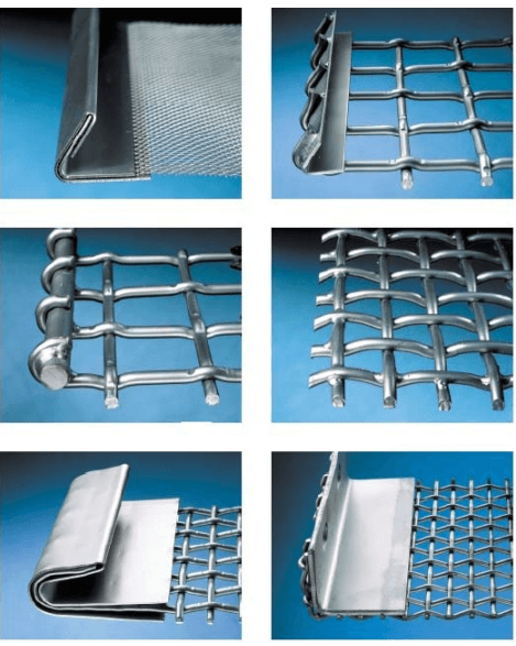
The sketches below demonstrate the four standard methods of fastening a screen cloth to the Dillon Screen. The choice of method is generally dependent on screen wire diameters. It is recommended that the following guide be followed:
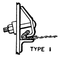
Type I: A bent metal reinforcement casing around the bent screen to form a hooked edge. To be used on screen wires having a diameter less than one-eighth inch.
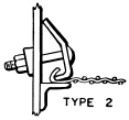
Type II: The wire is bent into a hooked edge and has no metal casing reinforcement. To be used on screen wires having a diameter from one-eighth inch to one-quarter inch.
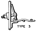
Type III: A one-half inch square bar is welded to the edge of the screen cloth. For screen wires having a diameter from one-quarter inch to three- eighths inch.
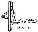
Type IV: For screen wires having a diameter three-eighths inch and above.
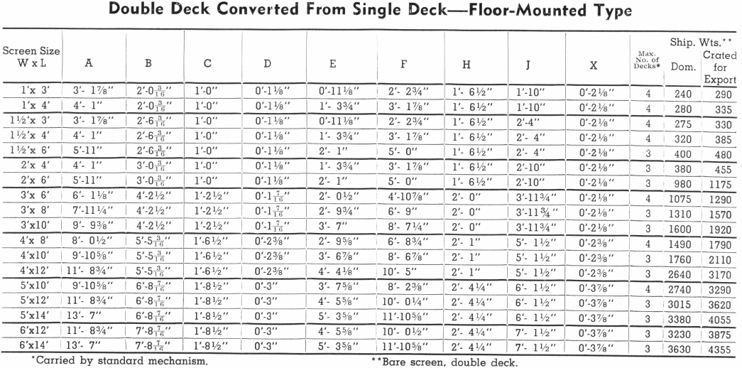
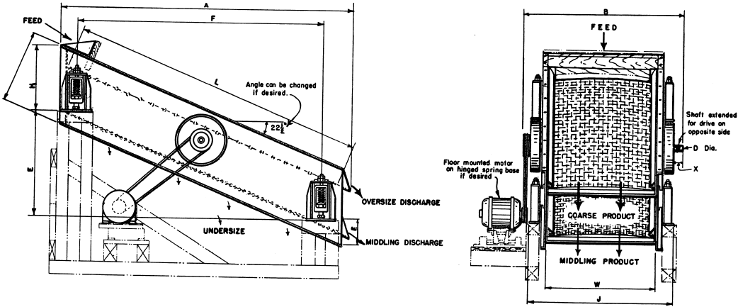
Double Deck Vibrating Screen—Floor Mounted
Source: This article is a reproduction of an excerpt of “In the Public Domain” documents held in 911Metallurgy Corp’s private library.

