Table of Contents
There are many different designs and styles of ball mill liners. As with grinding balls local economics and ultimately operating costs determine the best design and material to use. The initial set of liners is rarely the final design selected. Based upon individual experience, mill superintendents develop preferences for liner designs. The following is given as a guideline for the initial set of liners.
For 60 mm (2.5″) and smaller top size balls for cast metal liners use double wave liners with the number of lifters to the circle approximately 13.1 D in meters (for D in feet, divide 13.1 D by 3.3). Wave height above the liners from 1.5 to 2 times the liner thickness. 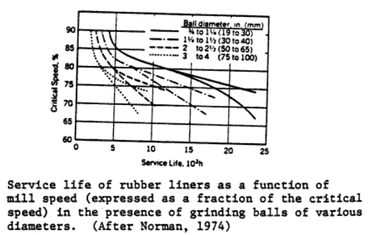 Rubber liners of the integral molded design follow the cast metal design. If using the replaceable lifter bar design in either metal or rubber the number of lifters should be about 3.3 π D in meters (for D in feet* divide 3.3 π D by 3.3) with the lifter height above the liners about twice the liner thickness.
The use of double wave liners, particularly when using 50 mm (2″) or larger balls, may show a loss of 5% or so in the mill power draw until the waves wear in and the balls can nest between the lifters.
When liners, and double wave liners in particular, wear with circumferential grooves, slipping of the charge is indicated, and this warns of accelerated wear. When the top size ball is smaller than 50mm (2.5″) and mill speed is less than 72% of critical wear resistant cast irons can be used. For other conditions alloyed cast steel is recommended. Rubber liners are well suited to this same area and not only reduce operating costs but can reduce noise levels.
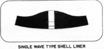
Single wave liners are recommended for larger size balls (50mm/2.5″ and larger). The number of the lifters to the circle equals approximately 6.6 D in meters (for D in feet, divide 6.6 D by 3.3). The liners are from 50 to 65 mm thick (2″ to 2.5″) with the waves from 60 to 75 mm (2.5″ to 3″) above the liners.
The replaceable lifter bar design made of either metal or rubber in about the same design proportions can be used. There could be a loss in power with rubber particularly if the mill speed is faster than about 72% of critical speed, and the ball size is larger than 75 mm.
Because of the impacting from the large balls, single wave liners for ball mills are usually made from alloyed steels or special wear-resistant alloyed cast irons. Because of the difficulty of balancing growth and wear with work hardening manganese steel is used infrequently and then with extreme care to allow for growth.
- End liners for ball mills conform to the slope of the mill head and can be made of rubber, alloyed cast steel or wear resistant cast iron. To prevent racing and excessive wear end-liners for ball mills are furnished with integral radial ribs or with replaceable lifters or with both.
When a grate discharge is used the grates and wear plates are normally perpendicular to the mill axis while the discharge pans conform to the slope of the mill head. The grates and wear plates are normally made from alloy wear resistant cast steel or rubber. They are ribbed to prevent racing and excessive wear. The dischargers and pans are generally made from either wear resistant cast iron or rubber, or wear resistant fabricated steel.Slot plugging can be a problem in grate discharge mills. Whether the grates are made of metal or rubber the slots should have ample relief tapered toward the discharge side. Total angles 7 to 10 degrees (3.5 to 5 degrees per side) are commonly used. Metal grates often have a small lead-in pocket or recess which can fill in with peened metal rather than have the slot peen shut. With the proper combination of metal internals and rubber surfaces, rubber grates have flexibility that tend to make them self cleaning and yet not fail due to flexing.
Except when using rubber liners, the mill surfaces are covered with a protective rubber or plastic material to protect the surfaces from pulp racing and corrosion.
This is done in wet grinding mills. Since dry grinding mills get hot due to heat from grinding generally rubber liners and rubber materials cannot be used.
Optimize Ball Mill Liner Replacement
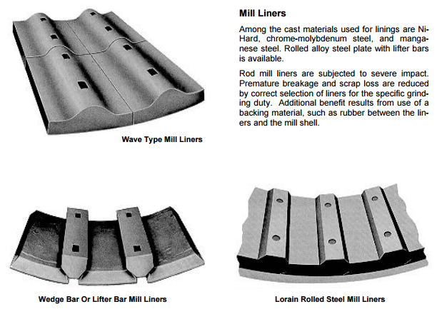
Shell liners may be furnished of various materials and of several designs. In each case the material used is the best obtainable, resulting in the lowest cost per ton of ore ground. The liner contours are selected for the specific grinding application and take into consideration liner wear, scrap loss, and mill capacity.

Liners cast of Manganese Steel, Ni-Hard, Chrome-moly, or other similar materials may be of the step type, block type, wave type, or the two-piece plate and lifter construction. These are illustrated on the right. During the past years of building ball Mills various other shapes of liners have been tried, such as the pocket type, spiral liners, etc.; in most cases it is found that these special shapes and designs are not justifiable from the standpoint of economics. They involve additional costs which are not generally recovered from an increased efficiency in milling operation.
Lorain Shell Liners
Lorain Shell Liners consist of high carbon rolled steel plates accurately formed to the mill shell radius. These are held in place by rolled alloy steel heat treated lift bars. This type liner is carefully engineered for the specific grinding application. Variations in lift bar design and liner plate thickness provide this flexibility of design for application.

All shell liners designed for ball mill operations are of such size and shape that they will easily pass through the manhole opening to facilitate relining operations. In rod mill work the design is such that they will easily pass through the large ball open end discharge trunnion.

Where cast liners are used, and especially in rod mill applications, we furnish rubber shell liner backing to help cushion the impact effect of the media within the mill and prevent pulp racing. With the Lorain type of liner such shell liner backing is not required. For special applications where severe corrosive conditions exist a shell liner of special alloys can be furnished and also the interior surface of the shell can be treated to protect such parts from the corrosive conditions.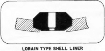
Mill HEAD LINERS
Head liners are of the segmental type constructed of Manganese Steel, Chrome molybdenum, or Ni-Hard and are designed to pass easily through the manhole opening or discharge opening in the case of rod mills. For ball mill work ribs are cast with the feed head liners to deflect the ball mass and minimize wear on the headliner itself.
In grate ball mill work there are no discharge head liners. The discharge grates and grate assembly replace these parts.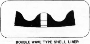
Mill LINER BOLTS
Where cast liners are used shell liner bolts and head liner bolts are made of forged steel with an oval head to prevent turning and loosening within the liners. These are held in place with two hex nuts and a cut washer. For wet grinding applications special waterproof washers can be furnished.

Effect of Liner Design on Mill Performance
The effect of liner design upon mill performance appears to have received little attention. Clearly, the main function of the liner is to form a removable surface to the null body, which may be replaced when seriously worn.
It is also clear however, that the metal plates which serve this purpose may have a surface which ranges from smooth in one which carries an intricate pattern of raised bars or sunken depressions. The merits of the various types do not appear, however, to have been studied.
As a first step in the analysis of the problem it would be expected that liners would fall into one or the other of two broad classes:
- Smooth liners,
- “Lifter” liners,
where “smooth” liners are those which have projections insufficient to give appreciable keying between the liner and the ball charge, whilst lifter liners are those which are so heavily ribbed as to give rise to appreciable interlocking between the balls and the liners.
Various common types of liners are illustrated in Fig. 6.12. Although these liners have various patterns of projections, or depressions, to give an amount of interaction between the liner and the grinding medium, it would be expected that wear would round the edges. It is doubtful whether, after some time in service, the performance of a mill with these liners differs appreciably from that of a mill with a smooth surface. Liners furnished with heavy lifter bars are also sometimes used and in such a case the locking of the ball charge to the shell must be very effective. Nevertheless, although a few vague general statements to the effect that a lifter mill gives a product with different size characteristics to that of a smooth mill have appeared, the point does not appear to have been widely investigated. It is probable, however, that, on the grounds of differences in the size characteristics of the products, there exists no sound reason for the use of lifters in preference to the normal smooth liners.
 |
 |
 |
 |
 |
 |
It is possible that, when a material with a low coefficient of friction is milled, the charge might slip on a smooth mill shell, with consequent loss of grinding capacity, and in such a case the use of lifter bars might well be the solution. It has also been suggested by one of the authors, Rose, that the use of lifter bars might eliminate the “surging” of the charge sometimes encountered in mill operation.
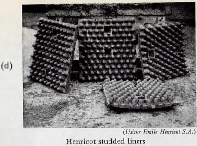
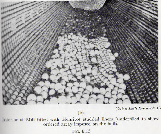
An entirely different conception of the duty of the mill liner underlies the design of the studded liner developed by Usines Emile Henricot of Count St. Etienne. These liners, illustrated in Fig. 6.12 and Fig. 6.13, consist of comparatively thin plate liners with uniformly spaced studs on the working surface; these studs being integral with the plate. Provided the spaces between the studs are not allowed to become choked with tramp-iron, etc., the studs furnish a good key between the shell and the charge which, it is claimed, leads to a greater power consumption and to improved grinding. Furthermore it would appear that the studs impose a definite geometrical arrangement in the outer layer of balls which, in turn, brings about a closer packing, throughout the ball mass, than obtains with conventional types of liner. This effect would also lead to improved performance. Evidence of this effect of the studs upon the packing of the charge appears in Fig. 6.13b, for the balls are clearly seen to lie in rows in the mill instead of in completely random array.
- 16 Types of GRINDING MILL Shell Liners & Designs
- 16.1 A-C LORAIN SHELL LINERS
- 16.2 WAVE BALL MILL SHELL LINERS
- 16.3 WEDGE SHELL MILL LINERS
- 16.4 Grinding Mill SPIRAL SHELL LINERS
An incidental merit claimed for these liners is that the high bearing pressure between the balls and the studs of the liners leads to work hardening of the studs; with a consequential reduction of the rate of metal wear.
The Henricot liners, which have been discussed in a paper by Belwinkel, appear to be the only attempt so far made to influence the grinding characteristics of a mill by means of correctly designed liners. It would therefore appear that there is some room for development in this direction.
 |
 |


