Gyratory Crusher Components

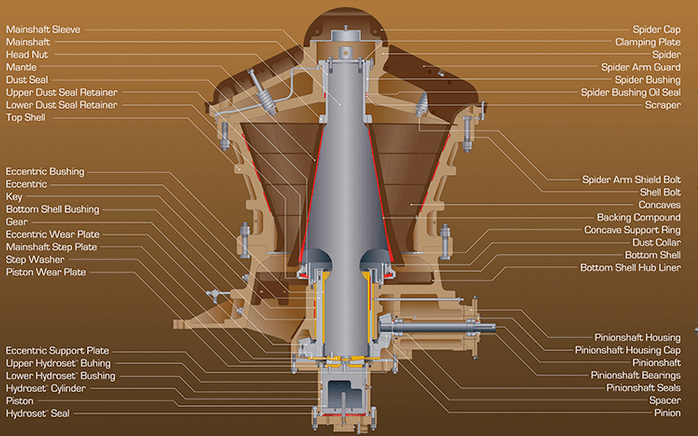
The Gyratory Crusher is made up of six main components, Base, Main frame and concave liners, Drive assembly, Mantle, Spider arm assembly, Oil system.  gyratory crusher parts
 

gyratory crusher base
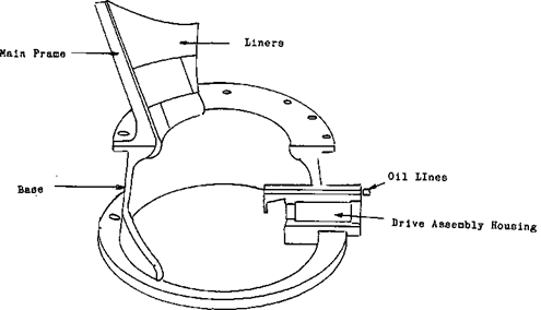
The base is the section of the crusher that provides an entry point for the drive assembly and oil system. It also provides support for the working surface of the main frame and liners.


gyratory crusher mantle
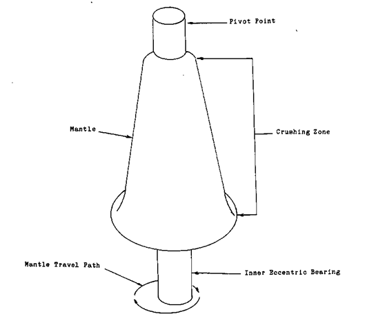
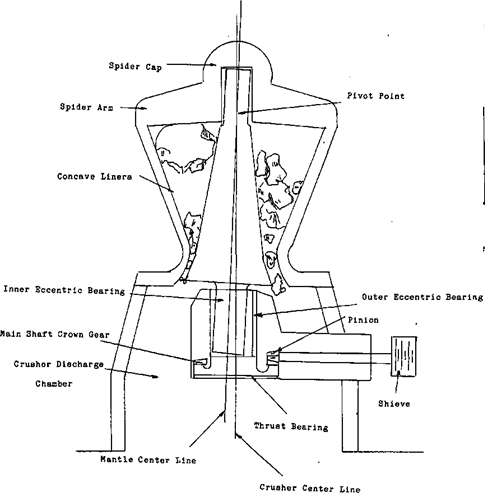
The mantle which is the movable working surface, is pivoted at its top within a spider bearing under the cap of the spider arm assembly while the bottom is gyrated within an eccentric bushing which is powered by the drive assembly. For your better understanding let’s take a closer look at this system so you can see how this particular crushing action is generated.


gyratory crusher drive assembly
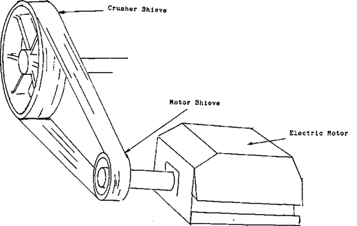
The drive assembly of a crusher may be directly driven from the MOTOR or have a CLUTCH SYSTEM to absorb shock. This will depend upon the size of the equipment. If you remember, earlier in the session I stated that the RPM of a primary crusher was in the 100 to the 200 revolutions per minute range. The RPM of the Electric Motor driving the crusher will be higher than this. Normally to reduce this speed, pulleys or as they are technically called SHEAVES will be used. The sheave on the drive line of the crusher will be much larger than the one on the drive line of the motor. This means that the big sheave will travel much slower than the smaller one on the motor does. By changing the SIZE RATIO between the crusher sheave and the motor sheave it possible to change the RPM of the crusher.


gyratory crusher gear drive assembly
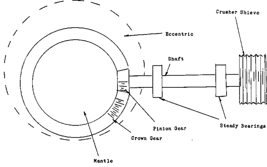
The individual components for the drive assembly, starting with the sheave is this, first the sheave which is attached to a SHAFT, on this shaft there are two STABILIZER BEARINGS and at the other end a PINION GEAR. A pinion gear is a small gear driving or being driven by a larger one. In this case the pinion gear is driving the larger one, the CROWN GEAR, this in turn is attached to an ECCENTRIC BUSHING and BEARING.

It is this eccentric bushing and bearing that gives the crusher its crushing action. To understand how it works it might help to learn the dictionary meaning of the word eccentric which is:

  1. Differing conspicuously in behaviour, appearance, or opinions.
  2. Not situated in the centre as an axis. Deviating from a perfect circle: said chiefly of an elliptical orbit.
gyratory-crusher-animation

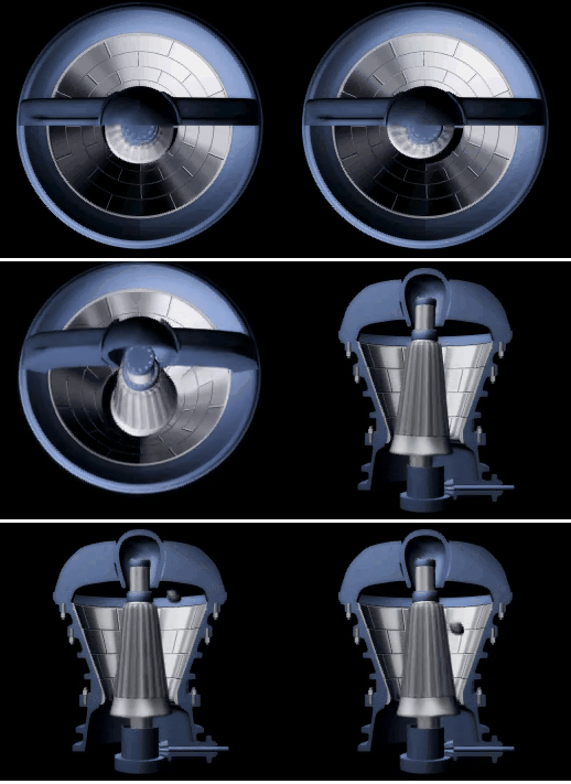
That means that in this case the centre of the MANTLE is off set from the middle of the CROWN GEAR. As the crown gear is turned the mantle is revolved in a circle. To complete the crushing action the centre of the top of the mantle is brought back to the centre of the crown gear and is pivoted in the SPIDER BEARING under the SPIDER ARM CAP. As you can see this causes the space between the CONCAVE LINERS and the MANTLE to open and close as the mantle revolves. Because the top of the mantle is pivoted the action at the top of the mantle is very little. The farther down the mantle you go the greater the crushing action becomes and the MANTLE to open and close as the mantle revolves. Because the top of the mantle is pivoted the action at the top of the mantle is very little. The farther down the mantle you go the greater the crushing action becomes.

https://www.911metallurgist.com/gyratory-crusher
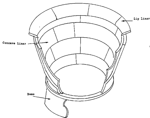
 

gyratory crusher liners -concave and lip
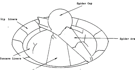
Gyratory Crusher Concave and Lip Liners


gyratory crusher spider cap
When you first look at the spider arm assembly it appears to only support the mantle. In reality it has two other important functions to perform. The first to SPLIT THE ORE LOAD as it enters the crusher, this helps in distributing the ore evenly over the crushing surface. The other function is to provide a PROTECTED PASSAGE for the lubrication lines that service the spider cap bearing.


Gyratory_Crusher_Parts
https://www.excelfoundry.com/replacement-components/gyratory-crushers-overview/