Table of Contents
The part that acceleration plays in starting a belt conveyor and its effect on belt conveyor design are well understood in a general way. Its practical importance is easily overlooked, however, and under some conditions, it is absolutely necessary to give the problem of acceleration detailed study.
Mathematical Analysis
In working out the various problems of conveyor belt acceleration, the starting point, as presented by the handbooks, is the familiar formula of “force of acceleration is equal to the mass times acceleration.” By expressing these fundamental quantities in terms of belt conveyor design, it is possible to arrive at the unsuspected conclusion that the acceleration time for horizontal belt conveyors is independent of the load, and instead, dependent upon the belt speed, the type of drive arrangement and drive pulley, and the idler coefficient of friction.
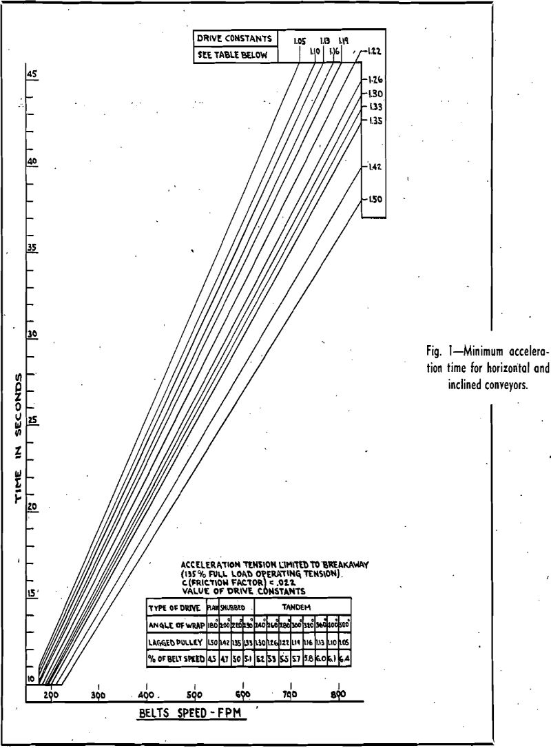
Obviously then, it becomes possible to graph the percentage of speed for each type of drive against the belt speed and accelerating time, after which, for a given belt speed and type of drive, the time can be read directly in seconds.
The other constant is the friction factor used for the idler equipment, which has been established as 0.022. For installations where it is necessary to establish the values of acceleration, invariably high grade idler equipment is used, and it has been established from field experience that 0.022 for the idler friction factor is amply conservative. The use of this friction factor for idlers must be tempered with judgment, of course, for occasions will arise where more power than indicated is required to start, even with the very best of equipment, such as low temperature operations that tend to congeal the grease in the bearings and thus produce additional friction drag.

Because the inclined belt conveyor requires less time for accelerating, it becomes convenient to use the chart prepared for horizontal belts, as doing so merely introduces a comfortable factor of safety.
Starting Time Control
After the minimum accelerating time in seconds has been accurately determined, the problem arises as to how this exact starting time can be introduced into the drive. Generally this can be accomplished readily through the use of a wound rotor motor and an external bank of resistance, with stepped starting. Such step controls are manufactured as standard equipment.
In selecting the control equipment, at least five points of starting should be used, which is standard procedure. The first two points will generally provide the building up of torque within the motor, and breakaway from rest will occur on the third point. Subsequent points add the final blocks of torque at the proper time intervals. While the time intervals for acceleration control usually will provide it automatically, sufficient length of contact at each point must be maintained to achieve stability at each point.
It is possible to achieve similar graduated starting control using dc motors. It is seldom however that dc motors are available, or their use economical, but mention of this type of. motor must be included.
A third type of control, reduced voltage starting for squirrel cage motors, also can be used in some cases, and since its application most frequently will be in connection with the treatment of acceleration for conveyors with vertical curves, discussion.of this type of control will follow subsequently.

A vertical curve in a belt conveyor becomes necessary when a transition from horizontal to incline is made. A large radius must be provided, to keep the belt from lifting off the idlers at the vertical curve, and the handbooks are all explicit in the determination of the minimum radius for such a vertical curve for running conditions.
However, in addition to the running condition, the effect of acceleration when starting must also be checked, as it is easily possible to have a condition in which no difficulty may be encountered with a loaded or partially loaded belt when running, but in which the starting of the empty belt may, cause momentary lifting and a sharp slapping back of the belt at the curve, which is-obviously an intolerable operating condition.

The effect of starting acceleration is accentuated by the use of across-the-line starting, and further by the surge of tension that is thrown into the belt, which passes the entire length as a wave. A further complicating factor is that larger motors than required are frequently used, either by the plant operator’s preference or occasioned by the fact that nothing smaller close to the actual requirement is available.
The complete vertical curve determination can therefore be summarized as follows:
- Determine the minimum vertical curve radius for the running condition.
- Determine the minimum vertical curve radius for the starting condition, using the locked rotor torque of the motor, and check for:
a—Crossline starting with the belt empty and/or partially loaded to the curve.
b—Reduced voltage. starting with the belt empty and/or partially loaded to the curve.
c—Full voltage starting, belt fully loaded. - Use the largest of the minimum vertical curve radii determined from 1 and 2 above.
- Whenever the belt is stressed to 80 pct or more of maximum tension rating, determine starting time in seconds (conveniently from Fig. 1), and use wound rotor motor with step starting controls.
