Since 1920 use of belt conveyor transportation has increased steadily, and capacity in tons per hour per unit has increased at about the same ratio. Belt conveyor systems for simultaneous two-way material transportation have been widely discussed, but heretofore have proved impractical for specific operations.
The two-way belt conveyor for coal mine service is not yet offered for sale as a unit by any manufacturer and must be built on order. This conveyor, with return run traveling parallel but opposite in direction to the outgoing or coal haulage run, permits not only haulage of coal from faces, but simultaneously permits transportation of men and supplies into the mine at any time. This eliminates, to a great extent, the necessity for rubber-tired supply and man haulage equipment and the maintenance of additional headings. Unlike conventional installations the return belt is in the open for inspection and maintenance.
The two-way belt haulage system is confined to a single heading on intake air, isolated from all other headings by stoppings on each side, and open for air circulation only at the main haulage way and at the faces. One additional heading, also on intake air, is maintained as an emergency rubber-tired haulage way, all other headings being center-posted and used as airways only until retreat work begins.
The chief problem in determining distance for the quarter-turn twist was to find a modulus of elasticity for the various ducks. Tests previously made on these ducks were reviewed and stress-strain charts were plotted. Two curves were drawn for each duck weight, these curves being the extremes of the scatter band.
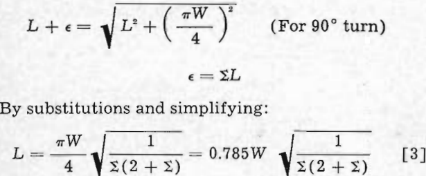
The following method is used to calculate distance required for the quarter turn,
Ts = Tension at edge of belt in the quarter turn drive, lb per ply in. Edge of belt travels helical path in making quarter turn.
Tm = Tension at center of belt, lb per ply in.
T = Total tension on belt, lb.
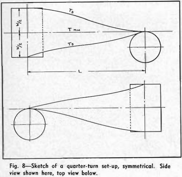
L = Center to center distance of vertical and horizontal pulleys, in.
Σ = Change in unit elongation from edge of belt to center of belt, in.
ε = Total elongation of edge with respect to center, in.
ΔT = Ts — Tm
E = Modulus of elasticity
W = Width of belt, in.
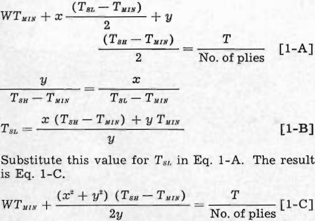
WTm + W/2 (Ts — Tm) = T/No. of Plies………………………………[1]
T is known from requirements of the belt. Tm has a minimum of O, and Ts a maximum depending on the weight of duck used. The maximum allowable tension for various duck weights is as follows: 28 ounce, 34 lb per ply in.; 32 ounce, 39 lb per ply in.; 42 ounce, 49 lb per ply in.; 48 ounce, 59 lb per ply in.
Σ = ΔT/E…………………………………………………………………..[2]
Since the path of any point on the edge of the belt in the quarter turn is a helix, the solution can be found by the triangular method whereby the helix is the hypotenuse of the triangle, the distance between pulleys the longer side, and the pitch and shorter side one half the belt width.

TSL = Tension in the low tension edge of the belt in the quarter turn drive, lb per ply in.
TSH = Tension in the high tension edge of the belt, lb per ply in.
TMIN = Tension in the minimum tension section of the belt, lb per ply in.
L = Center to center distance of vertical and horizontal pulleys, in.
y = Distance from high tension edge to minimum tension section, in.
x = Distance from low tension edge to minimum tension section, in.
ΣH = Change in unit elongation from high tension edge to minimum tension section.
ΣL = Change in unit elongation from low tension edge to minimum tension section.
ΔTH = TSH – TMIN
ΔTL = TSL – TMIN
E = Modulus of elasticity.
W = Width of belt, in.
T = Total tension of the belt, lb.


Belt manufacturers’ calculations show the two-way belt to be practical for lengths up to one mile with ordinary belting. For greater lengths a heavier belt is advisable. As an alternative, the conveyor system may be broken up into several flights of any convenient length.

