Table of Contents
- Experimental Procedures
- Fundamental Process
- Selection of Mold Materials
- Selection of Binder
- Slurry Preparation
- Preparation of Disposable Patterns
- Mold Production
- Pattern Removal
- Mold Curing
- Firing
- Melting and Casting
- Feed Material for Melting
- Casting Evaluation
- Effects of Mold Preheat and of Static Versus Centrifugal Casting
- Mold Metal Reaction
- Macrostructure
- Microstructure
- Mechanical Properties
- Hardness
- Tensile Properties
- Corrosion Resistance
One of the goals is to minimize the requirements for critical and strategic mineral commodities through conservation and substitution. As a part of this effort, the Bureau conducted research to develop molybdenum as a potential substitute for alloys containing the critical and strategic metals nickel, chromium, or cobalt. As expressed in Iron Age, this Nation has an adequate supply of molybdenum, but it has experienced a series of shortages in nickel, chromium, and cobalt during the last decade.
Although a plentiful supply of molybdenum is available, technology has not been fully developed for it to be used as a substitute for critical and strategic material in most applications. For example, it needs a coating to protect it from oxidation at elevated temperatures. The Bureau of Mines investigated potential coatings, and this research has been reported elsewhere. Another reason why molybdenum has not been more widely used as a substitute or alternate material is the high cost and difficulty of fabricating useful shapes from ingot or powder. A foundry process has not yet emerged that is suitable for the preparation of sound cast shapes. The need for a cast molybdenum or TZM (Mo-0.5 Ti- 0.08 Zr) turbine to operate at high temperatures has been discussed by Burman, who also described applications for cast molybdenum or TZM in diecasting, nuclear fusion components, hot gas valves and seals, pump equipment, and in tools for metalworking. Because of these stated needs, the Bureau of Mines undertook the task of investigating a casting technology to prepare useful shapes of molybdenum and molybdenum-base alloys.
Statement of Status
The most significant advances in forming molybdenum shapes were made in the 15-year period from the mid-1940’s to 1960’s. Prior to the mid-1940’s, powder metallurgy was the only process available for making molybdenum components. Purified molybdenum powder was pressed into suitably shaped blocks and sintered in vacuum or hydrogen to about 2,000° C (3,632° F). The sintered blocks were subsequently forged or rolled into plate or sheet, or drawn to wire. Sizes were limited, and uses were confined mostly to small electrical components. In 1946, Parke and Ham announced the application of consumable-electrode arc melting for preparing large molybdenum ingots. Arc-cast molybdenum ingots could be forged to produce commercial hardware, and the use of molybdenum as a structural material was advanced. However, only simple shapes could be made because molybdenum is impossible to form at ordinary temperatures, and it is rapidly oxidized when hot worked in air.
The next significant advancement came 14 years later, and it was made by the Bureau of Mines. In January 1959, the Bureau announced the first cast molybdenum shape. The development emanated from research on titanium and zirconium. Bureau researchers found that deep, large-volume metal pools of these reactive metals could be maintained in a water-cooled crucible during consumable- electrode arc melting, and the liquid metal could be poured into molds located within the furnace vacuum chamber. From this, the skull-casting process for casting reactive metals was evolved. The development has been the subject of several reports.
The success of the skull-casting technique with reactive metals led to experiments with other metals, including molybdenum, and the 1959 announcement was followed by a publication on molybdenum casting. Although the development discussed in this report was significant, the castings illustrated in the report were relatively simple because of limitations imposed by the type of mold available at that time—graphite. Because of the high melting temperature of molybdenum 2,610° C (4,730° F), molds for casting were machined from extruded high-density industrial graphite. These molds were expensive in terms of labor and material costs, and only simple shapes, that had no reentrant angles, complex curved surfaces, or cored sections could be economically cast. It was often only by destroying the mold that complex castings could be freed from the mold. In 1956, A. L. Field and R. A. Beall reported on the development of an expendable graphite mold for titanium casting that was analogous to conventional foundry sand molds. Later, the Bureau of Mines developed a completely water-free expendable graphite mold material for reactive metal casting. Molybdenum, however, was shown to react seriously with this material, and its use as a low-cost expendable mold source was precluded. As a result, molybdenum casting did not develop as an industrial source of hardware.
Nevertheless, industrial research continued. This research was spurred on by the need for a gas turbine to operate above 2,200° F, the theoretical maximum limit for usage of superalloys prior to the introduction of single crystal turbine blades. Some industrial investment casting foundrys tried to make castings in molds normally used for casting titanium, but to the best of the authors’ knowledge, completely satisfactory results were not realized. Therefore, research on improved turbine materials remained directed towards enhancement of superalloys, the development of new ceramics, or the use of fiber composite materials.
Statement of the Problem
A better investment mold had to be devised for casting molybdenum. Criteria for this material included the following:
- High strength—sufficient to contain molten molybdenum without breaking or eroding.
- Low reactivity—minimal reactivity with molten metal.
- Adequate thermal conductivity sufficient to enhance surface solidification to avoid fusion with the mold interface (“burn in”), but not high enough to cause cold laps and casting misruns.
- High melting temperature—greater than the melting temperature of molybdenum.
- Sufficient permeability—porous enough to pass released gases through the mold wall.
After reviewing the properties of refractory materials, zirconium oxide was selected as the most likely candidate. This choice will be discussed in detail in the following section of this report, but in general the selection was based on the preceding criteria as well as cost, availability, and low potential for health and environmental hazards.
Experimental Procedures
Fundamental Process
The basic process for making investment molds is essentially the same throughout the precision casting industry. The process involves five basic steps: (1) making a permanent metal die to form a pattern, (2) making a disposable pattern, (3) coating the pattern to make a shell, (4) drying the shell and removing the pattern, and (5) curing and firing the shell.
Starting at the beginning, a permanent die is made from an easy to machine metal (usually aluminum) to conform to the exact configuration of the desired casting. Into the die cavity, molten wax, plastic, or a wax-plastic mixture is injected or poured to form a disposable pattern. When solidified and cooled, the pattern should have the exact shape of the casting to be produced, but it must be slightly larger to compensate for shrinkage of the mold during curing, and for shrinkage of the cast metal during solidification.
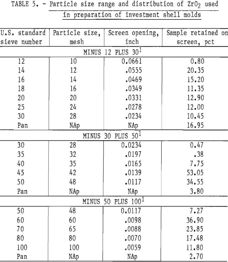
After forming the basic patterns, gates and risers are attached. These attachments are also made of disposable wax or plastic. The entire pattern assembly then is dipped into a slurry made of finely ground refractory material mixed with a fluid binder. After draining away the excess slurry, the pattern is sprinkled (stuccoed), while still wet with granulated refractory materials, The dip, drain, and stucco sequence is repeated several times until a self-supporting shell of desired thickness is formed around the pattern. Because permeability is important, stuccoing must be done with stucco grains of varying particle sizes as each successive shell layer is applied.
After air drying, the pattern assembly is removed from the shell by heating to melt the wax or plastic, or it can be removed by chemical dissolution. The monolithic molds thus formed are cured in air at 200° C (392° F) to 400° C (752° F) to remove residual pattern material and binder volatiles. This preliminary heating cycle is followed by firing at high temperature to convert the green shell to a strong ceramic mold. In this research, molds were fired to 1,650° C (3,002° F) in vacuum (discussion to follow) to achieve good bonding without sacrificing permeability.
Selection of Mold Materials
A list of candidate mold materials having melting temperatures higher than that of molybdenum 2,610° C (4,730° F) is given in table 1. This information, plus some preliminary experiments and experience gained from research on investment molds for titanium casting, was used to narrow the choice of candidate materials to two—ThO2 and ZrO2. These two compounds are thermodynamically stable and have very low vapor pressures at temperatures above their respective melting points. Both are readily available, but ZrO2 is less expensive and presents no appreciable hazard to health or environment. Therefore, ZrO2 was selected for this research.
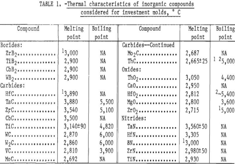
The preliminary experiments referred to in the previous paragraph included an evaluation of the behavior of both the monoclinic and cubic (stabilized) forms of ZrO2. Monoclinic ZrO2 was found to be unsatisfactory because the inner surface of the mold was subject to spalling and the mold proper was not dimensionally stable. These defects were apparent following high-temperature firing. They resulted from the large volume expansion that occurs during the transition of ZrO2 from monoclinic to tetragonal during heating above 1,000° C (1,832° F). Typical analyses of the various particle size oxides used to prepare molds for this study are given in table 2.
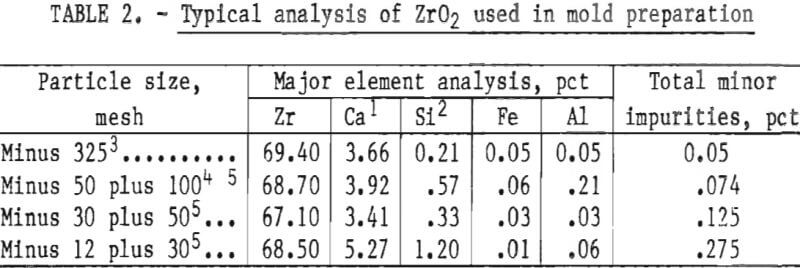
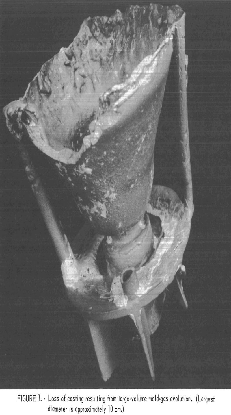
The high levels of silicon and aluminum were of major concern because of their low boiling temperatures. These impurities can lead to excessive mold gas evolution when contacted by molten molybdenum. This can cause porosity and other gas related defects in cast metal. The gas pressure can be high enough to empty the mold of its molten charge and leave only a hollow shell of metal in the mold cavity. This occurrence was experienced early in this research, and the result is shown in figure 1. To overcome this difficulty, volatile impurities had to be reduced from the mold during firing as discussed later.
Selection of Binder
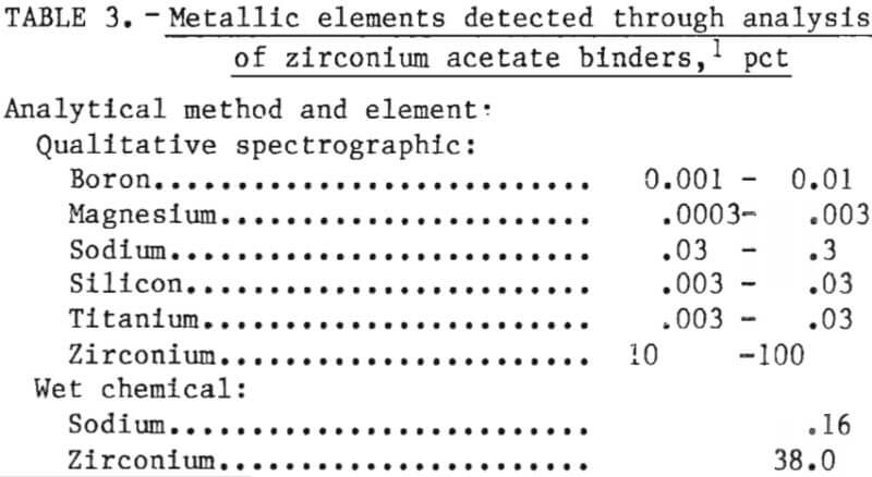
Almost all of the binders used in ceramic investment molds for casting ordinary (nonreactive) metals are formulations of aqueous or alcohol suspensions of colloidal SiO2. However, these formulations are not suitable for reactive metal molds because of mold gas generation as discussed above. For our binder, we chose zirconium acetate (Zr(C2H3O2)3OH) after studying a patent by R. A. and C. A. Brown. It was chosen because it converts to ZrO2 after curing and firing and, therefore, affords maximum compatability with the mold solids. It is mildly acidic (pH 3.2), and it gives off a distinct acetic odor. The actual composition of the binder used in this investigation is given in table 3.
Slurry Preparation
Investment slurries were prepared by mixing minus 325-mesh fused calcia stabilized ZrO2 in zirconium acetate. These slurries proved to be stable over extended periods of time (months) and displayed no tendency toward premature gellation. A detailed description of slurry preparation is presented in the section on “Mold Production.”
Preparation of Disposable Patterns
Expendable patterns were made with an injection molding machine that impelled molten wax, via air pressure, into permanent metal molds. A wax “casting” was thereby formed that duplicated the shape of the part to be cast. Sprues, gates, and risers were formed separately and attached to the pattern by wax welding to form a pattern assembly.
Special waxes are manufactured for foundry use that have a constant shrinkage to insure dimensional accuracy. These pattern waxes also must have a minimum amount of cavitation during solidification and have a fairly broad temperature range over which the wax can be injected into the die. The injection temperature range for the pattern wax used in this research is 132° to 140° F.
Mold Production
A general outline of the basic process for preparing investment molds was given in the first paragraph of the text under the heading “Experimental Procedures.” Some added details derived from recent experiments are given in the next paragraphs. Readers who require more background information on investment molds are referred to an earlier Bureau of Mines publication.
The investment cycle should start by thoroughly cleaning the wax (or plastic) pattern assemblies to free them of any residual parting agent (mold release). This can be done with a fluorinated base solvent, such as trichlortrifluoroethane, mixed with an equal volume of acetone. If this cleaning step is omitted, the first dip coat will not completely wet the pattern, and good adherence cannot be assured. The investment cycle begins by dipping the clean wax pattern assemblies into a slurry made up of minus 325-mesh ZrO2 flour, and aqueous ZrO2 forming binder (zirconium acetate). The binder-to-flour weight ratio of a 30- to 35-Zahn 4 second slurry mix, for example, was approximately 1 to 7. Small amounts of various materials were added to the slurry to improve the soundness of of the mold. These additives are a non-ionic wetting agent (sodium hepta-decyl sulfate, dioctyl sodium sulfosuccinate, etc.), a plasticizer (methyl cellusolve or glycerin), an antifoaming agent (ethyl hexanol or n-octylalcohol), a deflocculant (hydrochloric acid or water-soluble acrylic polymers), and green-strength promoters (polyvinyl alcohol). Individual additions ranged from 0.05 to 0.1 pct of the binder weight, except for the polyvinyl alcohol, which was varied from 1.0 to 5.0 pct of binder weight, and the ethyl hexanol, which was added very sparingly drop by drop until foaming was eliminated.
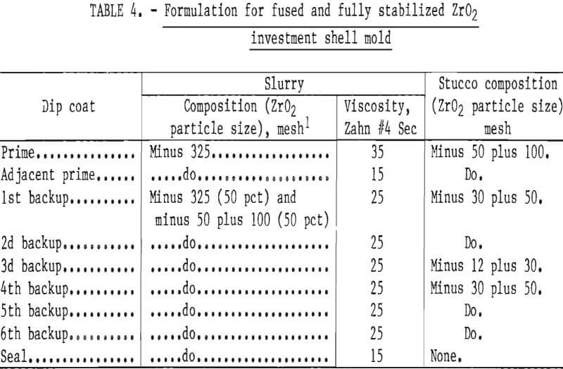
The prime coat slurry was mixed to a viscosity of 30 to 35 Zahn 4 seconds. Less viscous slurries resulted in inadequate pattern coverage and poor adherence. Thicker mixtures caused sags, folds, and wrinkles to form. These defects resulted in nonuniform stresses that weakened the mold.
The second and succeeding coats were considerably less viscous than the prime coat slurry in order to assure complete wetting of the dried previous coat and to avoid the formation of air pockets. This procedure gave added strength to the mold and prevented metal penetration through the relatively thin prime coat during the casting operation.
After each dipping, the pattern assemblies were drained of excess slurry, and then while still wet, sprinkled (stuccoed) with size graded grains of ZrO2. The grain size of the first stucco was minus 50 plus 100 mesh. Larger size particles of ZrO2 were used on succeeding coats to enhance shell properties. In order to prevent the previous coating from being dissolved by a subsequent dip coat, each stuccoed coat was allowed to dry to a solvent content below 20 vol- pct before redipping. We found that this took approximately 1 hour under controlled conditions of temperature and humidity in the laboratory.
Mold strength and permeability depend upon the number of coatings applied to a pattern, and upon the particle size and concentration of the oxide grains in the slurry and stucco. A slurry-stucco formula that appeared best for casting molybdenum or TZM is shown in table 4. The particle size range and distribution are shown in table 5.
The use of aluminum oxide (Al2O3), zirconium silicate (ZrSiO4), and olivine [ (Mg-Fe)2SiO4] were evaluated as backup layers over the ZrO2 inner layer in order to lower cost of molds. This work was not successful; molds backed with Al2O3 often cracked during firing at high temperature because of the thermal expansion mismatch between ZrO2 and Al2O3 and the volumetric changes that occur during phase transformations in these materials. In addition to this, the frequency of misruns in thin casting sections was inordinately high because of the high thermal conductivity of Al2O3. Castings made in molds backed by ZrSiO4 and (Mg-Fe)2SiO4 were characterized by gas-caused defects.
Pattern Removal
After air drying, the molds were de-waxed. In a commercial foundry, this is normally done by autoclaving or by flash firing. These techniques cause the wax in contact with the mold to liquefy before the bulk of the pattern begins to expand and cause the mold to crack. We removed the patterns by microwave heating. In this technique, heat is generated by the action of microwave energy on water molecules in the mold shell. This technique heats the mold evenly and melts the surface of the wax pattern, causing it to separate from the mold before the bulk of the pattern is heated and begins to expand. Therefore, no stress is exerted on the mold that can cause it to crack. The pattern continues to melt until it drops from the inverted mold.
A major advantage of microwave de-waxing over flash firing is that the bulk of the pattern wax can be reclaimed without further processing, whereas flash firing burns the pattern to ash and recovery is impossible. Pattern removal via microwave heating was shown to be inexpensive, fast, and clean.
Mold Curing
Following removal of the disposable patterns, the molds were heated to 200° C (392° F) in air to burn off wax residues from mold surfaces. Following this, the furnace temperature was gradually raised to 400° C (752° F) over a period of 4 hours and held for 12 hours while the mold cured in an oxidizing atmosphere» This step in the curing cycle removed pattern and binder volatiles, and stabilized and strengthened the mold by forming a bond between the ZrO2 in the binder and in the shell.
The bonding mechanism began when colloidal ZrO2 in the binder was converted to the crystalline form of the oxide. This conversion is apparently completed after several hours at 400° C (752° F), and at this stage the molds were strong enough to be handled without being damaged. Firing at still higher temperatures and for extended times resulted in grain growth and stronger bonding of mold constituents.
In order to determine the mechanism by which the mold materials coalesced to produce strong shells, desiccated samples of zirconium acetate were heated in air at various temperatures for extended periods. Cubic ZrO2 was detected by X-ray diffraction after the sample had been heated for a full 12 hours at 400° C (752° F). (No evidence of crystallization was observed in samples heated for shorter times or at lower temperatures.) Cubic ZrO2 was not expected because of the absence of modifying elements in the zirconium acetate and because of the relatively low heat involved in the conversion of amorphous ZrO2 to the crystalline form. Only monoclinic ZrO2 was anticipated. However, according to Duwez and Odell, if the average mean crystallite size of ZrO2 is very small, X-ray patterns will show cubic ZrO2 even when no modifiers are present, as is the case here.
Firing
After curing, the molds were transferred to a high-temperature furnace for firing. As the firing temperature was increased and grain growth occurred in the binder solids, additional transformations took place, as shown in table 6. These data show that ZrO2 in the zirconium acetate binder was converted from noncrystalline to cubic, and ultimately to the monoclinic form with increasing temperature. This form was shown to be retained at least up to 1,450° C (2,642° F).
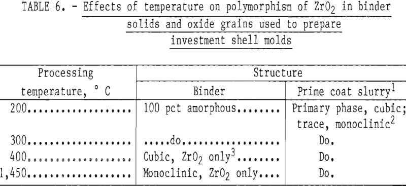
According to information advanced by the Zirconia Products Division of the Corning Glass Works, monoclinic ZrO2 crystals transform to the tetragonal form at -1,000° C (1,832° F) with a volume shrinkage of 7 pct. This transformation was confirmed by Garvie. Tetragonal ZrO2 has a lower thermal expansion than does cubic ZrO2, and if the two forms could be combined (cubic matrix with tetragonal binder), the product might be useful for molds because there would be a low tendency toward dimensional changes during thermal cycling. But tetragonal ZrO2 cannot be retained at room temperature regardless of quenching procedures because it is metastable and transforms very quickly to the monoclinic form. However, when fully stabilized ZrO2 is mixed with monoclinic ZrO2, a partially stabilized material forms that also has a lower thermal expansion than does fully stabilized, cubic ZrO2 (the expansion curve is uniform and nearly linear). Thus, the partially stabilized form is more useful for molds than is fully stabilized cubic ZrO2, which is subject to thermal shock. It follows, therefore, that when the monoclinic oxide, formed from the binder, was mixed with the fully stabilized cubic ZrO2 used to prepare the dip coat slurry, a partially stabilized ZrO2 mold shell was formed, and it proved to be quite resistant to thermal shock.
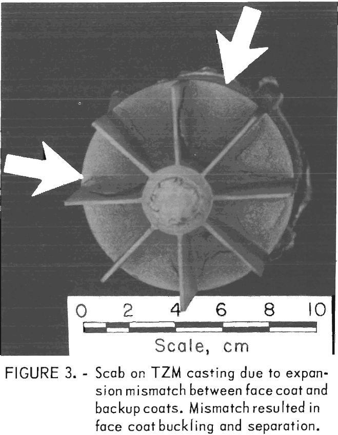
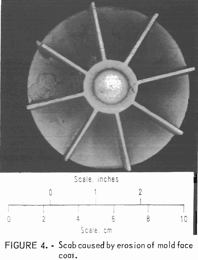
The most acceptable firing conditions were achieved by heating the molds in vacuum for 6 hours at 1,550° C (2,822° F) or for 4 hours at 1,650° C (3,002° F).5 All castings made in molds fired below 1,450° C (2,640° F), regardless of time, were characterized by gross defects caused by excessive mold gas and/or scabs and buckles caused by mold erosion and differential mold expansion. No advantage was found for firing the molds for more than 6 hours at 1,550° C (2,822° F) or for more than 4 hours at 1,650° C (3,002° F).
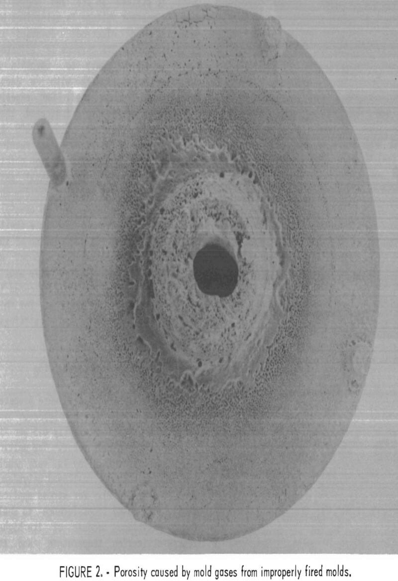
Examples of defects encountered in these experiments are shown in figures 2 through 4. Figure 2 shows porosity (blows) caused by mold gases. Figure 3 illustrates scab caused by mold expansion
and face coat separation. Finally, figure 4 shows scab caused by erosion of the mold face by molten metal.
Melting and Casting
A brief summary of the melting and casting procedures used in this research follows in this section. Readers requiring more detail are referred to previous Bureau of Mines publications.
The only system suitable for melting molybdenum is consumable electrode arc melting in a vacuum. In straight polarity arc melting using direct current power, the metal to be melted is the cathode (negatively charged). The water-cooled copper crucible and its contents are the anode (positively charged). Power was provided from a bank of selenium welding rectifiers connected in parallel to a common bus bar.
With the power turned on and the electrodes separated, a melt is ready to begin. The cathode is lowered
until it strikes an arc and begins to melt. Constant voltage is maintained by advancing the electrode downward as it is consumed. The current is adjusted at a level necessary to maintain a desirable melting rate with a deep, large-volume molten pool. Our experience with molybdenum indicated that this current should be from 1,600 to 1,800 amp/in² of electrode cross section at about 40 volts potential to obtain satisfactory results. During skull casting, the cathode is melted rapidly and the metal that contacts the cold crucible wall immediately freezes to form a skull. During casting, the liquid portion of the metal, which comprises about 85 pct of the charge, is poured from this skull. The metal is teemed into molds located in a lower chamber of the furnace. For this research, both static and centrifugal castings were poured.
Feed Material for Melting
Consumable electrodes were prepared from TZM, a high-strength molybdenum-base alloy that contains nominally 0.5 pct Ti, 0.08 pct Zr, and 0.02 pct C. The melting temperature of this alloy is very nearly the same as that of unalloyed molybdenum 2,610° C (4,730° F). For stress applications, it is used in preference to unalloyed molybdenum because of its higher recrystallization temperature and its superior toughness. These benefits result from finely dispersed complex carbides in the molybdenum matrix. However, the presence of these carbides tend to increase the alloy’s reactivity with ceramic oxide molds.
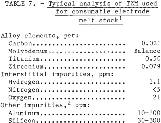
Rectangular laminated bars (2½- inch by 2½-inch in cross sections) were fabricated by TIG welding strips of TZM that had been sheared from 3/16- inch—thick plate. The plate had been obtained from Government surplus. A typical analysis of the TZM used is presented in table 7. For comparative purposes, several melts were made with previously melted unalloyed molybdenum. We found no significant differences in melting and casting characteristics between the TZM and the unalloyed molybdenum. A small increase in mold metal reaction occurred with TZM, but it was not significant. The reaction was attributed to a partial reduction of ZrO2 by carbon in the alloy to form CO gas.
A few heats were made to determine if pressed and sintered compacts of unalloyed molybdenum powder could be used for casting. We found the powder metal electrodes to be too gassy. Gases adsorbed on the surface of the numerous small grains of powder were desorbed when the compacts were melted. When the molten metal was poured, gases were entrained in the fluid stream of metal and became trapped at the interface between the mold and the molten metal. Thus, surface gas pockets and some internal porosity were formed in the solidified metal as shown in figure 5. These defects did not occur when the electrodes were
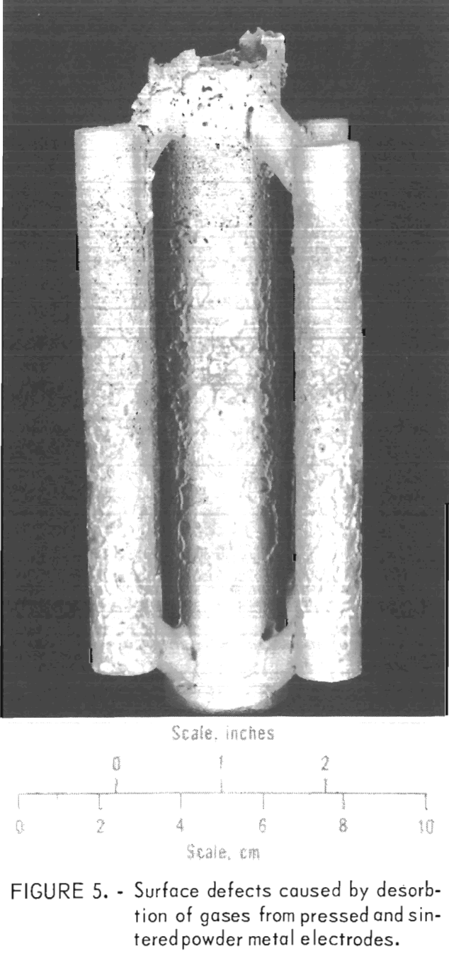
formed from previously melted powder metal electrodes.
Casting Evaluation
TZM castings comprising both single complex shapes and clusters of simple shapes, were made to evaluate molds developed in this research, and to determine the properties of the castings prepared therein.
The complex shape was a turbine impellar. Castings of this configuration weighed about 16 pounds each, and had both thin and heavy sections with severely constricted flow areas. They were used to determine the interrelated effects of mold preheating, centrifugal versus static casting, the ability of the molds to vent gases through the mold shell, and to assess the degree of mold erosion caused by high-velocity entry of superheated TZM through constricted flow areas.
The other castings comprised clusters of four 5/8-inch-diameter rods. The rods were 5 inches long and were centrifugally cast to minimize the occurrence of internal defects and misruns. The sole purpose of these castings was to provide blanks for preparing specimens to evaluate mechanical properties of cast TZM.
Effects of Mold Preheat and of Static Versus Centrifugal Casting
The effects of preheating molds was determined with a series of statically poured impeller castings. Preheat temperatures ranged from 100° C (212° F) up, to 500° C (932° F). As expected, metal fluid life was increased with increased mold temperature, and the misruns common in thin sections of unheated molds were eliminated. However, the amount of mold-metal reaction was markedly increased as the mold preheat temperature was increased.
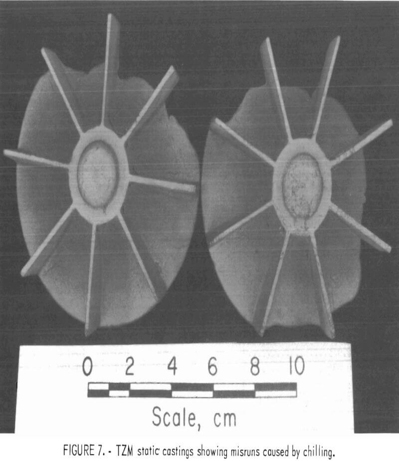
Figure 6 shows a typical example of a statically poured TZM impeller cast in a ZrO2 ceramic shell mold that was cured under optimum conditions and subsequently preheated to 200° C (392° F) prior to casting. Figure 7 shows a TZM casting that was produced in an identical mold that was not preheated. Note the misruns in vane sections of the casting in figure 7 and the evidence of mold-metal reaction in figure 6. It is apparent from these photographs that preheating, even to the relatively low temperature of 200° C (392° F)s does much to minimize misruns in thin mold sections caused by premature freezing of cast metal, but at the same time, preheating seriously increases the amount of mold-metal reaction.
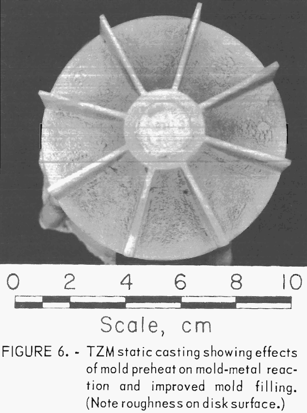
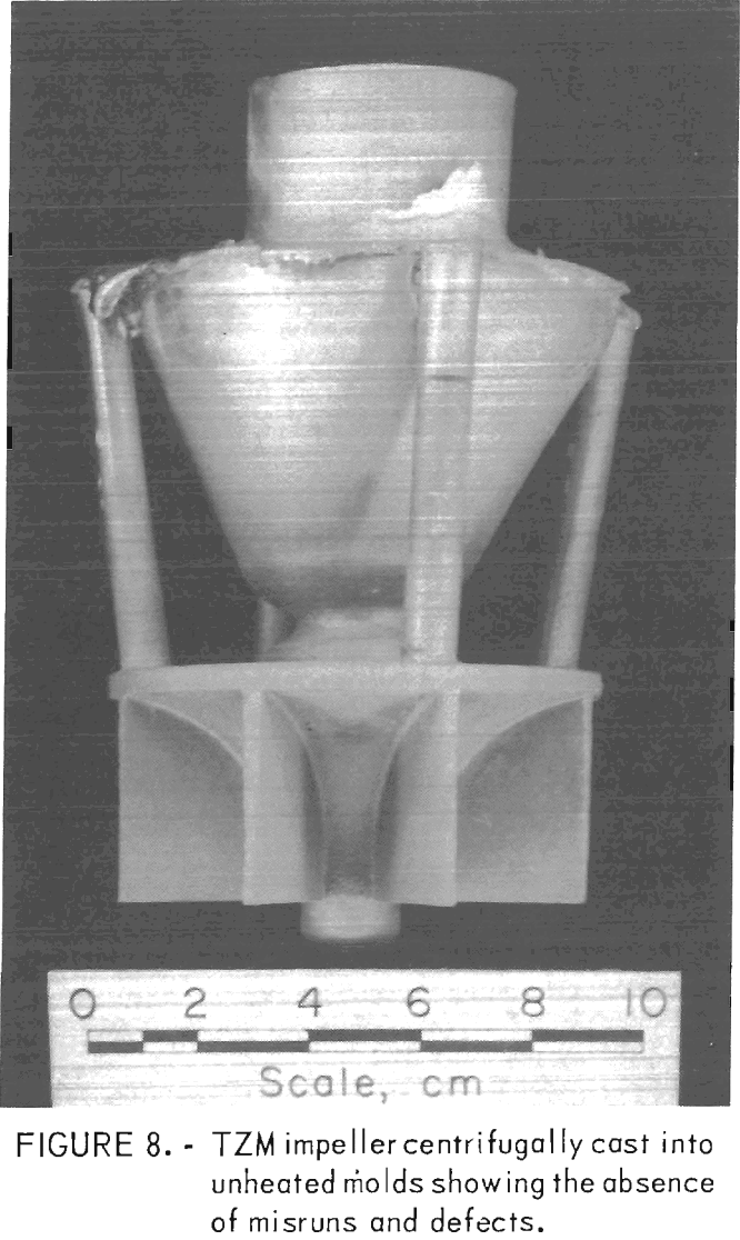
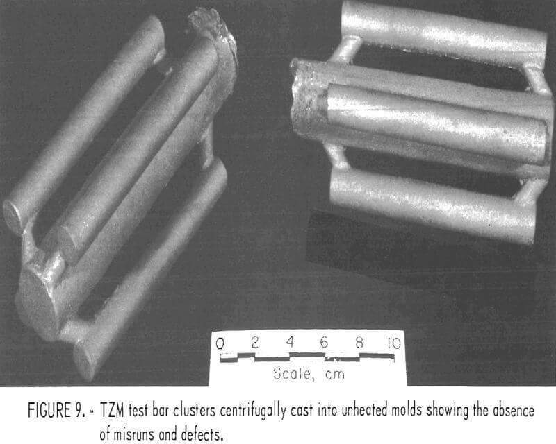
To circumvent these problems, centrifugal casting practices were adopted. We found that good-quality castings were produced when molds were cast at 14 g centrifugal force. Figure 8 shows a TZM impeller, and figure 9 shows TZM test bar clusters. Both of these shapes were prepared by centrifugal casting into unheated molds. The slightly roughened surface shown in these two photographs is equivalent to the surface characteristics of good-quality ferrous alloy castings produced in rammed sand molds. We assume that this surface texture results from incipient melting of the mold inner-face coat when it is initially contacted by molten TZM [estimated to be superheated to approximately 2,750° C (4,882° F)].
When this occurs, the softened mold face coat appears to be superficially penetrated by superheated metal.
The absence of serious gas-caused surface defects indicates that the molds were sufficiently permeable to relieve normal amounts of gas through the mold shell. Centrifugal casting enhanced this condition. Excessive amounts of mold gas, such as results from mold-metal reaction in preheated molds, and large volumes of gas from powder metal electrodes could not be eliminated in this manner, and serious casting defects resulted. These conditions were discussed previously.
Mold Metal Reaction
Metal samples were removed for analyses from five randomly selected impeller castings at several locations on the castings, and at progressively increased depths in these sites. The results are given in table 8 together with an analysis of a head sample of the melt stock for comparison.
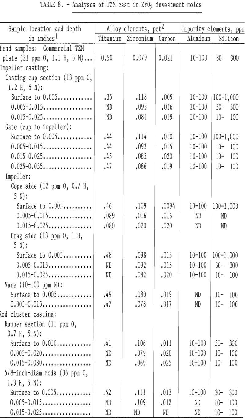
The data show differences in the levels of C, Si, and Zr at the casting surface compared with levels in the head sample. A gradual return in concentration of these elements to near melt stock levels with increasing sample depth is also evident. These data indicate that minor mold-metal reactions occurred at the mold-metal interface, and we offer the following hypothesis to explain the reaction: Superheated TZM, containing ZrC, comes into intimate contact with the ZrO2 mold that contains SiO2 as a major contaminant (tables 2 and 3)c This ZrC decomposes at the high temperature and low pressure (-0.05 mm Hg) to yield free zirconium and carbon. The SiO2 in the mold also decomposes under the same conditions to liberate oxygen. Also, excess oxygen atoms become available when calcia stabilized ZrO2 is heated to high temperature at reduced pressure.
We postulate that free carbon from the alloy reacts with the excess oxygen to form CO, which evolves as a mold gas. The reaction is probably diffusion controlled, and the net result, a depletion in carbon accompanied by corresponding increases in zirconium and silicon, is apparent only in a shallow layer of the casting surface. The latter two elements may combine to form a ZrSiO4 case on the the casting, but this was not identified.
Macrostructure
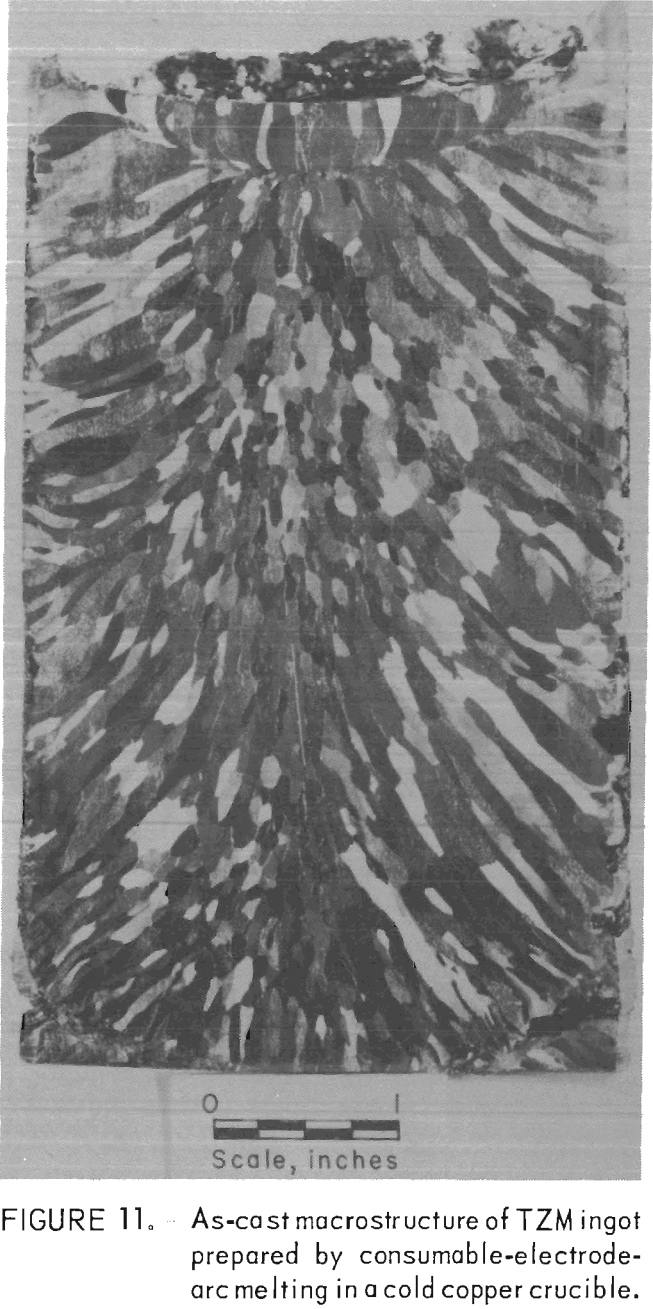
The grain structure of all the TZM castings was equiaxed, and individual crystals were relatively large compared to castings of most other metals and alloys. But they were small compared with an arc melted TZM ingot where columnar grains, ¼-inch in cross section and 2 to 3 inches long, are common. A comparison can be seen in figures 10 and 11.
Figure 10 shows the as-cast macrostructure of a TZM impeller produced by skull casting in a ZrO2 investment mold. The average grain size is 730 grains/in². Individual grains range in size from 0.013 inch to 0.079 inch in diameter.
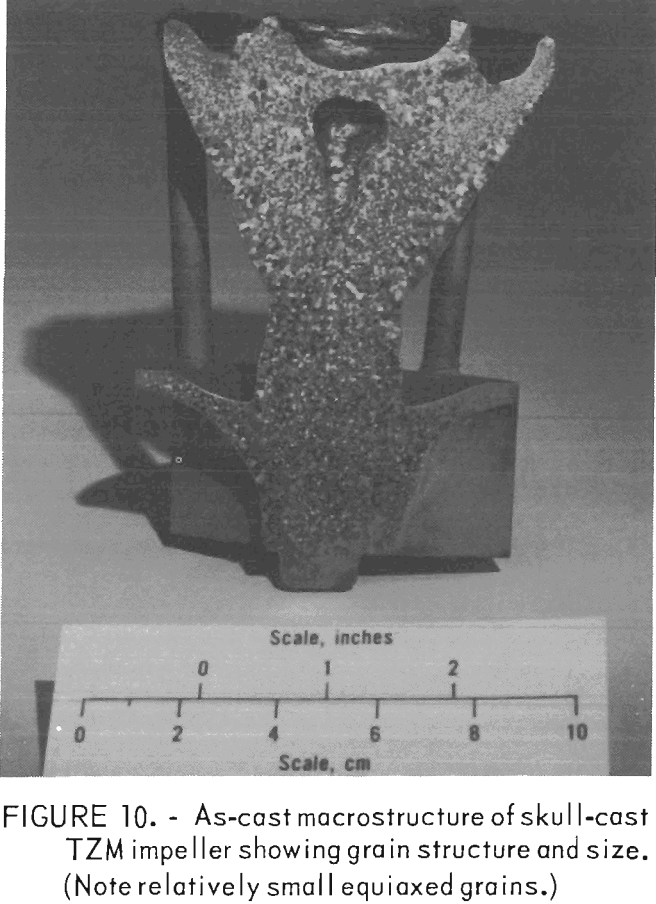
Figure 11 shows an as-cast macro-structure of a TZM cold-mold ingot produced by arc melting. The photograph is of a longitudinal section of a 3½- inch-diameter ingot.
Microstructure
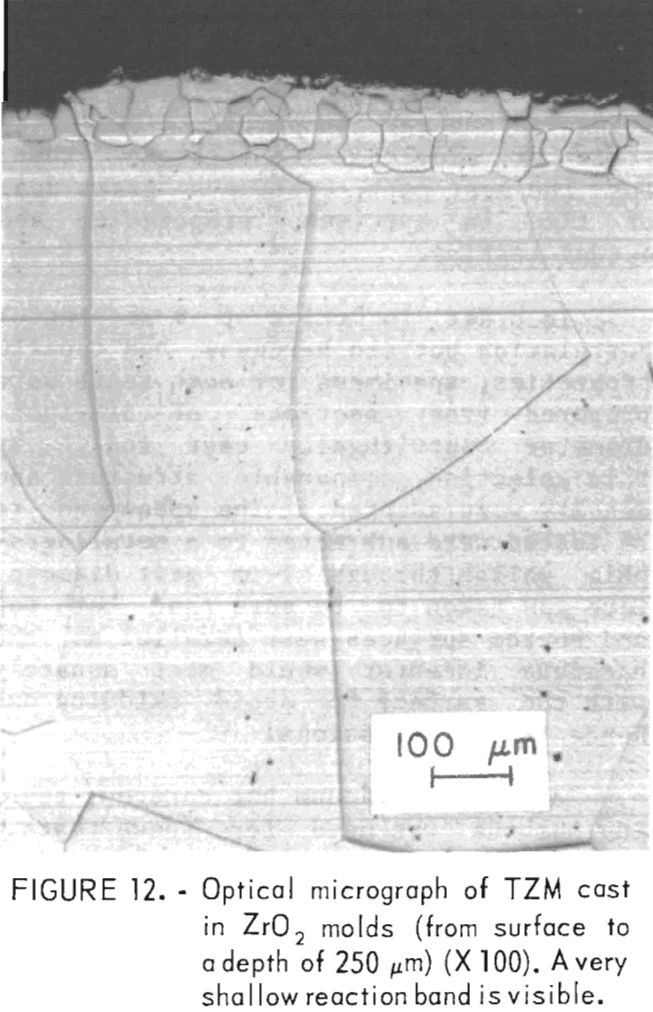
A typical microstructure of TZM cast in ZrO2 mold is shown in figure 12. Here, the cast structure is shown from the casting surface to a depth of about 250 µm at X 100 magnification. Figure 13 shows the same structure at X 400. Obviously, the reaction layer is quite thin—from 0.01 to 0.0175 mm. An electron microprobe analysis of this layer detected 0.3 pct Si. If titanium or zirconium was present in this zone, the concentration was below the limit of detection for the analytical method used. The zone immediately below this zone penetrated to a depth of 1.2 to 1.4 mm. It contained 0.1 pct Si and 0.1 pct Ti but no zirconium. Apparently, most of the titanium and zirconium was precipitated out of the molybdenum lattice.
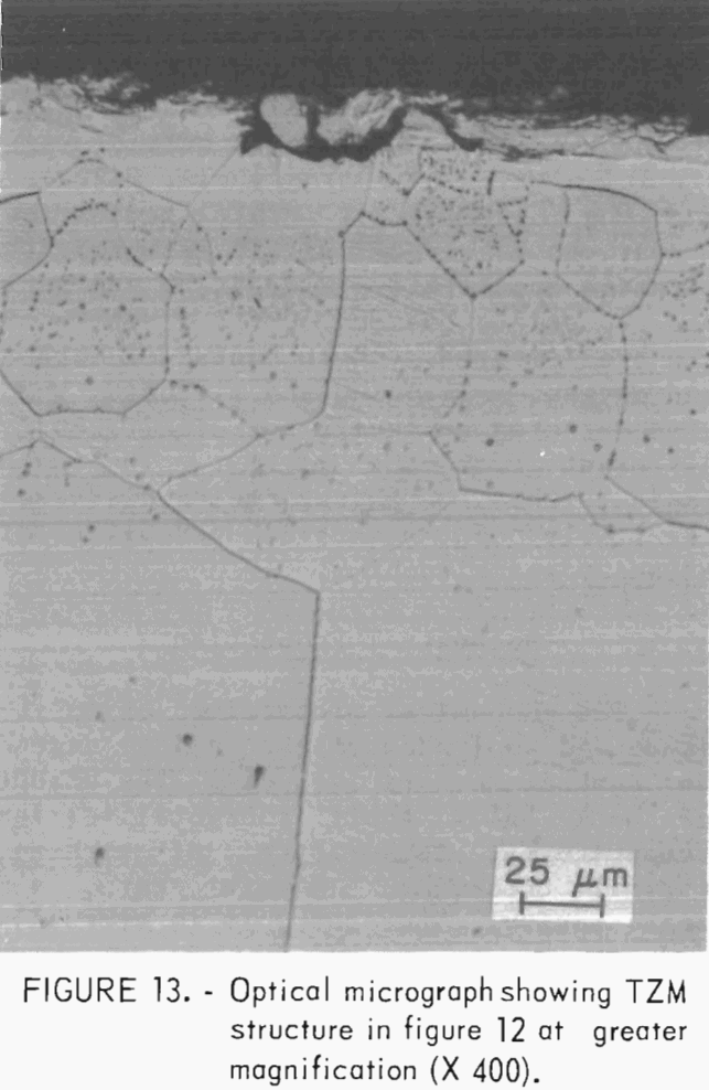
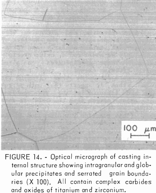
Both titanium and zirconium were found to be present near the surface of samples both intergranularly and intragranularly as small round oxide precipitates. These precipitates contained mostly titanium except at their centers, where more zirconium than titanium was found. Thus, it appears that both zirconium and titanium in the TZM combined with excess oxygen from the mold to form oxides as did the carbon to form mold gas. (This reaction was discussed in the previous section.) Zirconium had the greater affinity, and it evidently combined first to form nuclei for the precipitates which grew in size by combining with the more abundant titanium. From this surface layer on into the casting Interior, the alloy composition and microstructure appeared to be normal. Titanium and zirconium levels were close to those reported for the alloy melt stock. The microstructure of this area is shown in figure 14. The most noticeable features are intragranular acicular and globular precipitates, and serrated grain boundaries that also contain small precipitates. The intragranular material and the material at grain boundaries appear to be identical in composition although quantitative microprobe analysis was impossible because of the fineness of the precipitates. Both contained carbon and oxygen. Titanium and zirconium were also detected at levels not significantly different from the matrix. The data indicate that the phases being discussed are likely complex carbides and oxides of titanium and zirconium.
Mechanical Properties
The mechanical properties of molybdenum and molybdenum-base alloys depend on several factors including the amount of work below their recrystallization temperatures, temperature of working, thermal treatment, strain rate, and metal purity. Therefore, it is virtually
impossible to relate the as-cast properties of TZM shapes produced in this research with the large amounts of data reported from various sources that present, without exception, the properties of wrought materials of a variety of shapes and sizes produced by diverse mechanical and thermal treatments. Therefore, the data presented here can only be compared with data for as-cast material of identical grain size and composition. Of interest, however, are differences that exist in selected properties of the castings compared to properties of wrought and fully recrystallized bar stock of similar size.
Hardness
According to Ham, one of the most useful and simplest tests for determining the load carrying capacity of an alloy at elevated temperatures is the Vickers hot hardness test. It provides a fast, inexpensive screening prior to more definitive tests for evaluating mechanical properties of materials at elevated temperatures that, for the most part, consume a great deal of time in specimen preparation and actual testing.
In order to arrive at a meaningful correlation between hardness and tensile properties, specimens for both tests were prepared from sections of 5/8-inch- diameter centrifugally cast rods. By this selection, comparable structure and density were assured. The specimens to be tested were subjected to a metallographic polish through 1-µm grit diamond. Care was taken to be sure that both top and bottom surfaces were parallel so the hardness indentor would meet squarely with the surface to avoid skidding and hence false impressions.
A Marshall vacuum hot hardness testing machine was used for these tests. Temperatures to 3,000° F can be readily attained with this equipment,. However, because the indentor tip was made of sapphire, which should not be used above 2,912° F, hot hardness determinations were not made at full equipment capability.
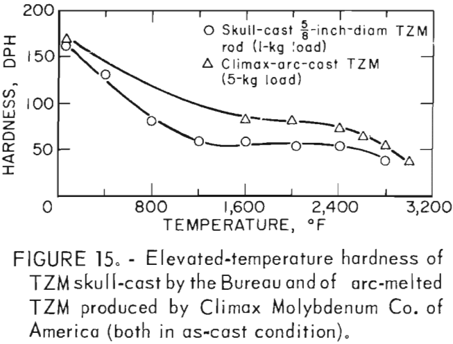
Hardness determinations were made at temperatures from ambient room temperature to a maximum of 2,800° F in 400° F increments on three representative specimens. A complete range of temperature indentations was made on each specimen in order to develop a measure of confidence in the data obtained. The test chamber was maintained at reduced pressures between 1 x 10⁻⁵ and 2 x 10⁻⁵ mm Hg over the entire temperature range. A 1-Kg load was applied to the sapphire indentor over a 12-second dwell time for each hardness determination. Filar readings of each indentation were made at room temperature using the optics of a Tukon Microhardness Tester, and diamond pyramid hardness (DPH) was calculated from the filar readings. Data from these tests are presented in table 9. These data show an average value of three determinations at each temperature. Figure 15 is a plot of these data, along with published hot hardness data developed by Climax Molybdenum Co. covering the same temperature range. Similar curves are shown; differences in values can be attributed to the difference in applied load and possibly in testing procedures.
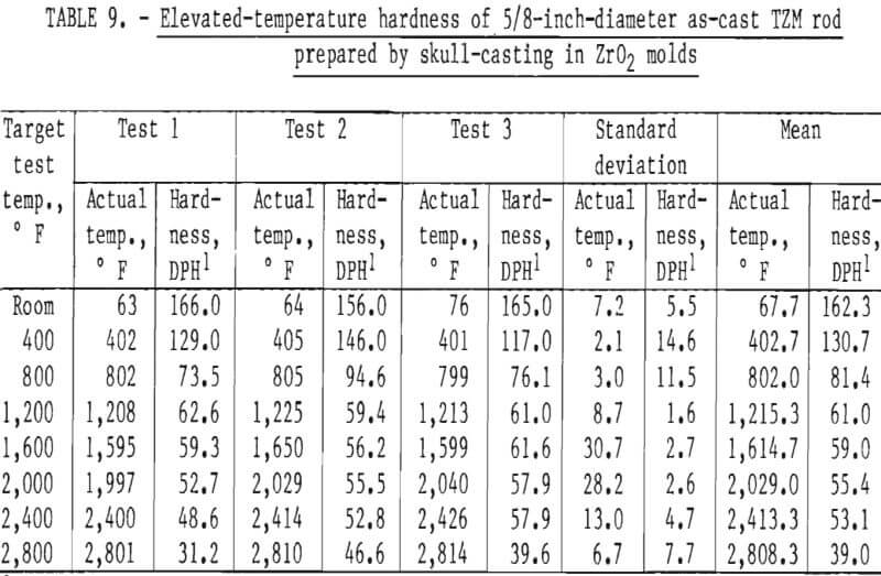
According to Climax Molybdenum Co. (10, fig. F), hardness values for TZM can be converted to approximate tensile strength by the same conversion relationship used for unalloyed molybdenum. This relationship is shown in figure 16. In accordance with this, and data from table 9, room-temperature tensile strength of our castings should range from -59,500 psi to -74,000 psi. If the relationship can be extrapolated beyond the plotted data, the tensile strength range of the castings should be from -15,000 psi to -32,000 psi at 1,600° F. At 2,800° F, the range of strength should be from -6,000 psi to -23,500 psi.
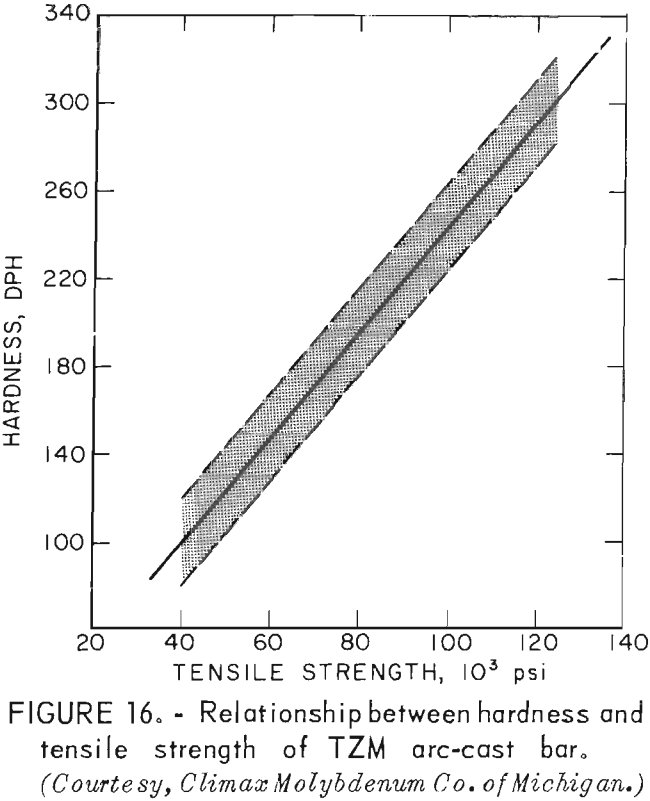
Actual data from testing the skull-cast rod at the above temperatures show tensile strengths to be at the upper end of the predicted range, However room-temperature strength was lower than predicted by hardness measurements.
Tensile Properties
Tensile tests were performed on standard ¼-inch-diameter specimens that were machined from centrifugally cast rods. The reduced section of all specimens was ground to a finish of 16 rms to minimize the possibility of failure from surface defects. Room-temperature tensile tests were conducted on a Baldwin Universal Testing Machine, using a calibrated P53M, 1-inch extensometer to measure strain. All elevated-temperature tests were conducted on a Marquardt TM-1 test machine. It was equipped with self-resistance heating within a controlled environment chamber. All tests reported here were conducted in vacuum. A Class B nonaveraging extensometer was used with this machine; consequently, strain measurements were not sufficiently accurate to determine the modulus at elevated temperatures. Room-temperature tests were conducted with a uniform strain rate of 0.05 in · in-¹ · min-¹. The strain rate for elevated-temperature tests was 0.005 in · in-¹ · min-¹ through yield and then 0.05 in · in-¹ · min-¹ to failure of the specimens.
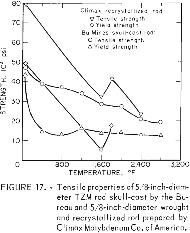
A summary of the tensile properties is presented in table 10. A strength versus temperature plot of these data and similar published strength values for 5/8-inch-diameter wrought and fully recrystallized Climax arc-cast rod, are shown in figure 17. This figure clearly shows the effect of prior work and grain size on the strength of the alloy at room temperature. The strength of skull cast and wrought materials are nearly equal from 1,600° F to the highest temperature tested. It is not known where they converge because data between room temperature and 1,600° F for the commercially produced rod were not found in the literature. The reason for the abrupt increase in both tensile and yield strength of the recrystallized commercial rod between 1,600° F and 1,800° F is not understood. This behavior was not observed on the skull-cast TZM. Furthermore, hardness data presented in table 9 and shown graphically in figure 15 do not indicate this anomaly.
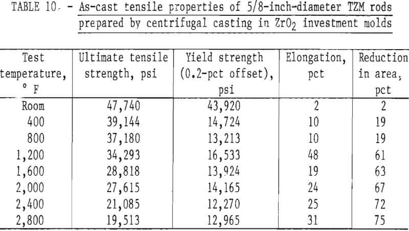
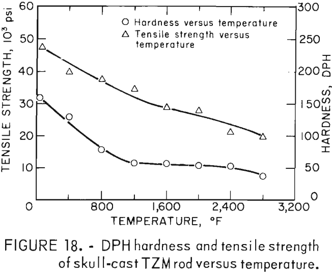
Figure 18, a plot of DPH hardness and tensile strength of 5/8-inch-diameter skull-cast TZM rod versus temperature, clearly shows the relationship that exists over a broad temperature range. These data indicate that at service temperatures above the recrystallization temperature, skull-cast TZM parts may be as useful in stress applications as is hardware prepared by hot working techniques. Elevated-temperature creep and stress rupture data, however, are needed to substantiate this premise.
Corrosion Resistance
The room-temperature corrosion resistance of skull cast TZM in various aqueous solutions was tested to determine the influence of surface condition on the rate of corrosion. As-cast specimens were conditioned by polishing with a 120-grit abrasive cloth on a wet belt sanding machine. Other as-cast specimens were tested with surfaces not conditioned.
Corrosion tests were conducted with test specimens completely immersed in aerated distilled water solutions of the corrodents, and in the corrodent vapors. The test temperature was ambient room temperature, which ranged from 18° to 23° C (64.4° to 73.4° F) over the duration of the tests (10 days).
The corrosion rate in mils penetration per year (mpy) was calculated according to the equation presented in ASTM G31-72, which is as follows:
Corrosion rate (mpy) = 3.45 x 10 6 x W/A x T x D
where W = mass loss in grams to nearest 1 mg,
A = area in square centimeters to nearest 0.01 cm²,
T = time of exposure in hours to nearest 0.01 hour,
D = density in grams per cubic centimeter.
Data presented in table 11 indicate that, as a rule, the resistance of cast TZM to corrosive attack by most corrodents is a direct function of surface smoothness. The polished specimens tended to be attacked more slowly than the unconditioned cast specimens. Exceptions to this are seen with both concentrated and diluted HNO3 and with FeCl3. It seems reasonable that the differences in corrosion rates between the as-cast and polished specimens are due to the increased surface area of the as-cast over polished specimens because of roughness. In addition we observed changes in the levels of C, Si, and Zr near the casting surfaces compared to the head sample and samples removed from below the surface. Polishing then not only reduced the exposed surface area, but also altered the composition of the exposed surface.
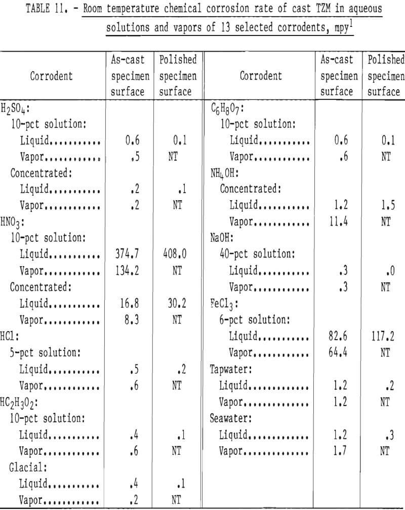
All the solutions tested, with the exceptions of sea water and concentrated NH4OH, were more corrosive as liquids than as vapors. The corrosion rate of cast TZM was relatively insignificant in all corrodents tested except FeCl3 (1), NH4OH (g), and HNO3.
Data from these tests are supported by information published by the National Association of Corrosion Engineers that shows molybdenum to be quite resistant to chemical attack by most common industrial acids and alkalies except oxidizing acids such as HNO3. The relatively low resistance to low concentrations of FeCl3 shown in our tests is confirmed by W. L. Acherman, who reported that the rate of corrosion of TZM by HCl is increased substantially with the addition of iron ions (present as FeCl3).
Results of corrosion tests in alkaline solutions show low corrosion rates in concentrated NH4OH and in 40-pct solutions of NaOH. However, attack appears to be significantly increased if NH4OH is present as a gas. Acherman reports that TZM is slowly attacked in the above named bases, but the rates were significantly higher at lower concentrations and higher temperatures than examined in our tests.
Conclusions
The results of this study show that small molybdenum and molybdenum-base alloy castings can be successfully made in stabilized ZrO2 investment molds.
A satisfactory mold formula comprised dip-coat slurries of minus 325-mesh, fused, calcia-stabilized ZrO2 in zirconium acetate. Patterns coated with these slurries, when stuccoed with size-graded particles of stabilized ZrO2 (also fused), were found to form sound, dimensionally and thermodynamically stable shells when properly cured and adequately fired. These molds are sufficiently strong and erosion resistant to permit castings weighing at least 16 pounds to be centrifugally cast at 14 g centrifugal force.
The minimum firing parameters required to stabilize ZrO2 molds for molybdenum alloy casting appear to be 1,550° C (2,822° F) for 6 hours, or 1,650° C (3,002° F) for 4 hours. Firing at lower temperatures or shorter time periods fail to produce adequate strength and/or stability.
The surface quality of TZM and unalloyed molybdenum is not as good as is characteristic of the more common investment-molded metal castings. This somewhat undesirable feature appears to result from superficial fusion of the mold innerface during contact with molten TZM. Casting dimensions and details are, however, predictable and reproducible.
The room-temperature tensile strength of investment cast TZM in the as-cast condition is in no way comparable to the tensile strength of the wrought alloy in the recrystallized condition. With increasing temperatures, the strengths of the two begin to converge until they are nearly equal at 1,600° F. The higher strength values for the wrought alloy appears to result from the fine grain size and the effects of prior work. Our data show that castings of TZM should be equally as good as wrought and recrystallized TZM for applications at and above 1,600° F. Where complicated shapes are required; the use of castings at these temperatures should be economically and practically more desirable.
The corrosion characteristics of cast TZM, in general, were found to be quite similar to those found in the literature for both TZM and unalloyed molybdenum. Our data indicate that castings, probably because of shallow surface roughness, tend to be less resistant than wrought materials to attack by corrodents. Exceptions to this characteristic were indicated for HNO3 and FeCl3.
