Table of Contents
When excavating open-pit mines below the water table, two of the more important water-related problems potentially faced by mine operators is the amount of ground water that could flow into the pit and the effect of pore water pressure on the stability of the highwalls. The ability to predict the nature and magnitude of these potential problems, so that adequate dewatering or depressurizing systems can be installed, can have significant impacts on the economics of a mine.
Inadequate Discretization – How the flow domain is subdivided into finite, geometric pieces (i.e., how it is discretized and incorporated into a model grid) will have a significant effect on the predictions of inflow and the shape of the phreatic surface near the pit. Not only do discrete features such as faults and contacts between significantly different hydrogeologic materials (which invariably are components of an orebody) need to be included, but the essentially radial flow to a pit is more accurately predicted by a grid spacing, that is small or approximately logarithmically spaced near the pit.
Disregarding Non-Darcian Flow – Ground-water flow near outlet points such as springs, excavations, and wells, particularly in fractured rock, is often non-Darcian.
Poor Representation of Seepage Faces – The seepage face, the surface on the highwall above the bottom of the pit through which primarily lateral flow occurs, is. usually not properly estimated. The height of the seepage face effects both the amount of lateral inflow and, obviously, the height of the phreatic surface (and, hence, the pore pressure) in the highwall.
Development of Numerical Flow Code
The governing equation for three-dimensional, saturated-unsaturated flow of ground water under both Darcian and non-Darcian conditions is

where
h = hydraulic head [L],
K’ij = effective hydraulic conductivity tensor [LT-¹]
kR = relative hydraulic conductivity [ ],
S’s = effective specific storage [L-¹l
t = time [T],
xi = a coordinate [L], and
W = all sources or sinks in terms of discharge per unit volume [T-¹]
-dh/dl = 1/k q + bq²………………………………………………………….(2)
where
q = ground-water discharge in direction of flow [LT-¹] ,
l = direction of ground-water flow [L],
K = hydraulic conductivity under Darcian flow conditions [LT-¹], and
b = a coefficient [L-²T²].

where
qi = component of ground-water discharge in direction xi [LT-¹l
Kij = hydraulic conductivity tensor for Darcian flow [LT-¹] and
bij = tensor form of the coefficient b in Equation 2 [L-²T²]


where
P = pressure head [L],
x3 = vertical coordinate [L], and
k’R = relative hydraulic conductivity in domain above phreatic surface [ ].
S’s = Ss + Sy A/V…………………………………………………………………(7)
where
Ss = elastic specific storage of water and matrix of media [L-¹],
Sy = specific yield at the water table [ ],
V = specified volume of media [L³], and
A = area of water table within specified volume of media [L²] .
This piecewise-continuous solution is defined by coefficient values that are specified at the nodes in the model grid. Functional values between the nodes are calculated by using piecewise-continuous interpolation or basis functions that depend on the coefficients and are defined over the elements. MINEDW utilizes tetrahedral elements and linear interpolation functions.
To simulate the excavation of a pit, MINEDW provides for removal of elements and corresponding inactive nodes. The input file identifies the elements representing the excavation that are to be removed in a specified time step. The code automatically removes any nodes that no longer are associated with any remaining element.
Demonstration Problem
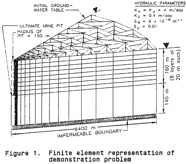
Assuming axisymmetric conditions, the demonstration problem is described by the finite element grid and hydraulic parameters. The radius of the cylindrical pit is 150 m, and it is excavated to a total depth of 160 m below the initial water table in eight equal stages of 20 m that are continuously excavated in 182 days (0.5 year) each. An impermeable bottom to the aquifer system is assumed to exist at a depth of 140 m beneath the ultimate pit. Because of the assumed axisymmetry of the problem, it can be solved using just a segment of the system; we have arbitrarily used a 45-degree slice.
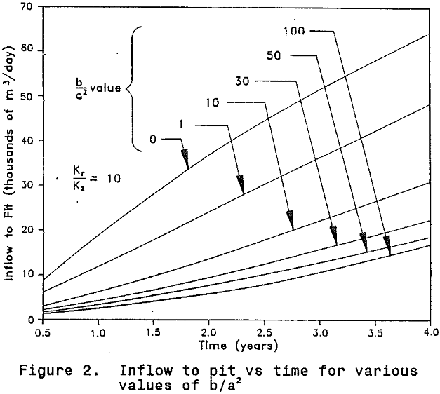
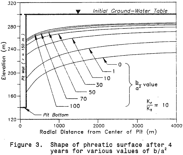
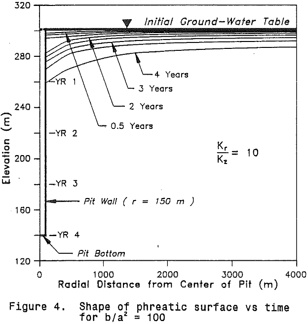
It is worth noting that for the case of b/a² = 100, MINEDW predicts that about 64 percent of the total inflow enters near the corner of the pit, about 9 percent up through the floor, and about 27 percent through the seepage face.
