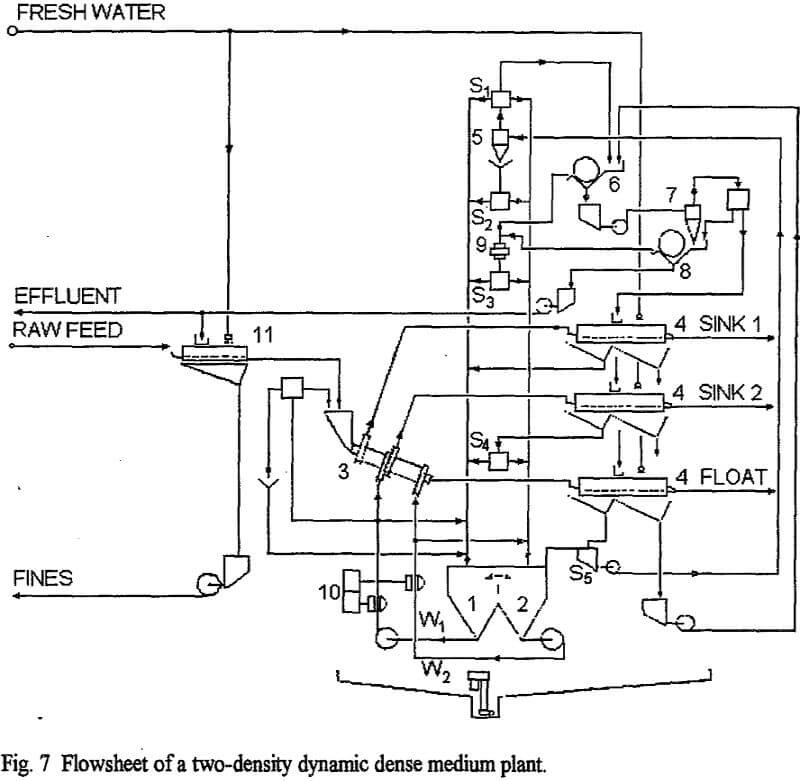
The two-density separation by dense medium cyclones was generally performed using two dense medium plants in sequence. In contrast to the former technology, the multi-density separation can now be performed by using a single medium circuit composed of different interconnected medium sumps. The sumps, one for each density, are fed with different medium streams selected according to their density, size composition and content in non-magnetic contaminant in such a way that the rheological properties of the media are optimized.
The DMS process with two separation densities was employed in the past using static vessels. The best known apparatus for this application is the Wemco Drum in its dual-gravity, three-product system version, which was employed in the size range 6 to 200 mm. However, apart from the case of preparation of coarse coals, with the static system some of the above mentioned goals – e.g. a marketable barite or a high grade chromite concentrate suitable for smelting – are practically impossible to reach. In feet, for such results to be obtained the degree of liberation of the minerals must be high: in practice one must operate on small sizes, e.g. less than 10-12 mm. This means that dynamic systems have to be employed.
The two-density dense medium circuit
The two-density dense medium circuit must:
(a) allow the preparation in two sumps of two media of different densities, as required by the process;
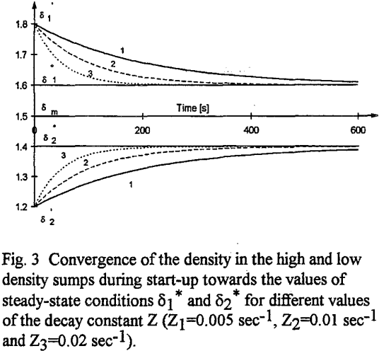
(b) have a stable behavior, which implies the stability both of the dense medium volumes at the different densities in the sumps and of their density values, but most of all the convergence of the system – after chance perturbations or during plant start-up – towards the density values defined by the operating variables;
(c) permit differentiating the composition of the medium streams returning to the sumps in such a way that the rheological characteristics of the media at different densities be within the ranges required by the process to be performed.
A symbolic representation of the circuit indicates the sumps for the media of density δ1 and δ2. A1 and A2 are the entering streams, B1 and B2 the exiting streams. C is a compensating stream to balance the medium volumes in the sumps. D1 and D2 are density gauges. The box G contains all the remaining equipment of the plant: the multistage dynamic separator, draining and washing screens, dilute medium sumps, densifying cyclones, magnetic separators, splitters, launders and piping.
The plant feed is represented by F, q and w. F is the amount of coarse solid material. The amount of fines of the same material (passing through the opening of the draining and washing screen) is q, including both these fines that pre-exist in the feed and those that are formed during the process, q is therefore the amount of fines entering and contaminating the dense medium. The water entering together with the feed is indicated by w.
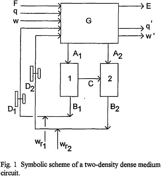
In addition, the water wr1 and wr2 necessary for the density control also enters the plant. Exiting the plant are E, q’ and w’: E=E1+E2+E3 represents the separation products, three for a two-density separation; q’ represents the non-magnetic contaminating fines (same in nature as q), which are extracted by the regeneration system; w’ is the water extracted by the regeneration system.
In the circuit illustrated symbolically the only sites of accumulation of medium solids are the sumps 1 and 2, since in the piping, the separator, the cyclone and the magnetic separators the volume of dense medium is small compared to that of the sumps. For this reason, and also in order to make the calculations easier, we will analyse a simplified system consisting of the two sumps and their connection.
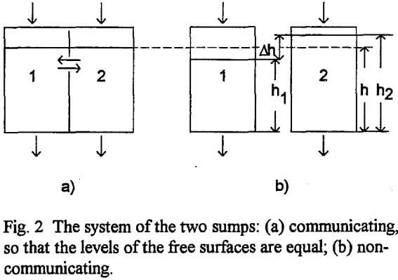
For the sake of simplicity there can be considered the case in which the two sumps are equal and therefore the equality of the level of the free surface of the dense medium in them gives V1=V2, where V1 and V2 are the volumes of the dense medium in the sumps 1 and 2, respectively.
Discussion
To make the analysis more simple and understandable to the reader, we have made some assumptions which – as will be seen later – do not affect the validity of the results.
The first assumption is that h1=h2, i.e. the levels of the free surface of the medium in the two sumps are equal. As already pointed out, this is hardly practicable, as some difference in level is necessary for the compensating flow to take place. However, the difference in level can be kept at a low value by adopting a large intercommunication cross sectional area between the sumps. This is easy to accomplish if the two sumps have a wall in common in which there is an opening. This opening should be large enough for a low Δh/h to be obtained, but adjustable and designed in such a way to avoid undesired interferences between the two sumps. As already mentioned, another way to reduce Δh/h is to adjust the splitters that form the flows entering the two sumps so as to minimise the necessary compensating flow.
To define the values of the medium density in the two sumps we have introduced the factor K, which represents the weight fraction of the total medium solids going to the sump 1. K gives no indication about how the medium solids will be divided on the basis of size and density.
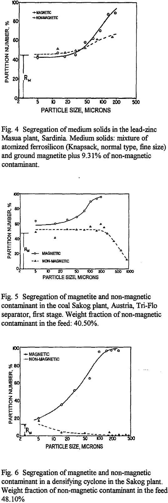
– the high-density sump should be fed prevalently by coarser and heavier particles of the medium solids and, thus, less fines and less non-magnetic contaminant so as to keep the viscosity low;
– the low-density sump should be fed prevalently by finer and lighter particles of the medium solids and, thus, more non-magnetic contaminant in order to maintain a good stability.
Applications
At present, 9 two-density dense medium separation plants using the technology described in this paper have been installed. Three of them treat fluorite ores with associated heavy minerals, one of them treats chromite ores, another ferrochrome slags, two plants treat metallic scrap and two are pilot plants (Esso Resources, Alberta, Canada and Enadimsa, Madrid, Spain).
The first plant has been installed by Prealpi Mineraria S.p.A., Italy, for treating fluorite ores containing galena and other sulphides and producing a fluorite concentrate of metallurgical grade with CaF2 in excess of 90% and S content less than 0.25%. The high density cut extracts the galena and galena/fluorite middlings, the low density cut separates the fluorite of metallurgical grade from the tailings. The galena/fluorite middlings are treated by flotation. A similar plant, for producing metallurgical grade fluorite concentrates, is operating in Brasil (Mineracao Floral, Criciuma).
Three plants process secondary materials: one of them processes ferrochrome slags (Bergslagens Suomi Oy, Tornio, Finland), and the other two metal scrap (Metallhuttenwerke Bruch, Dortmund, Germany, and A.R. Metalli, Lombardia, Italy).
