 SRL Pump stands for Soft Rubber Lined, which means that it is designed to pump a slurry and is lined with soft rubber. There are other forms of lining that may be used for different types of acidic or highly abrasive slurries and of course companies experiment with different materials trying to increase the life of the liners. But rubber is the basic or standard lining for these pumps.
This pump Operating principle works based on an IMPELLER. A Propeller propels a vessel through a liquid an Impeller impels, drives or pushes forward.
In other words the slurry is pushed out the discharge pipe.
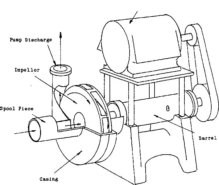
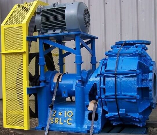 The impeller that does the pushing is a rapidly spinning disk that has vanes or surfaces to catch the slurry and force it in the correct direction.
For this pump to work correctly, the feed must first be fed into a pump box. This is to provide the pump with surge capacity. The pipe that connects the pump box to the pump is called the spool piece. It leads to the casing that surrounds the impeller. The discharge pipe that the impeller forces the slurry into is connected to this casing.
The distance or height the pump is able to pump to is dependent upon the speed of the pump, the type of the impeller, the size of the discharge line and the density of the material.
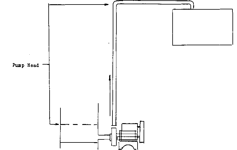
This type of pumping action develops two forces that work on the pump. The first is what is termed as the pump head.
This is the Operating pressure that it takes to lift or pump the material to its destination. The greater the volume, density of the material or height that it is being lifted to, the greater the head pressure. This pressure will be at its greatest in the IMPELLER CASINO.
The other force that is developed is a VACUUM caused by the slurry displacing the air in the discharge pipe, this is similar to a SYPHON as the liquid travels up the pipe it pulls the liquid directly behind it. The vacuum is most evident at the entrance to the pump. This is because the impeller starts the slurry moving at this point, so this is where the vacuum is created.
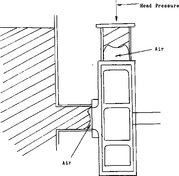
These two pressures are important to the operator, let’s discuss the vacuum first as it is still fresh in our minds. As I mentioned the purpose of the pump box is to provide SURGE CAPACITY for the pump. It also maintains a HEAD PRESSURE on the PUMP CASING. If this box should run empty for a moment, the syphoning effect of the pump will be stopped as air is introduced to the pump. Having air in the pump instead of slurry, the pump will not have anything in it to pump out of the discharge. Without fresh feed entering the line the forward motion of the slurry will stall.
Pump Air Lock: The incoming feed will not be able to reach the impeller of the pump due to the air holding it away. This causes the incoming feed to begin filling the pump box trapping the air inside the pump. This is known as an AIR LOCK.
Troubleshooting Pump Air Lock: To correct the situation one of two things have to happen. One, if the capacity of the pump box is large enough to hold enough slurry, the pressure that is built up as the pump box is filled will force the air bubble past the pump impeller allowing the pump to begin pumping once more. If, for some reason, this is not possible, say the pumps discharge line is too flat or the density of the material too heavy to allow the air to move. The pump may have to be shut down for a moment to allow the slurry to run back down the line pushing the air bubble out of the pump.
Preventing Pump Air Lock: To prevent this from happening, either be sure the flow to the pump is great enough to keep the intake of the pump covered so air cannot be introduced, or provide an escape route for the air by way of a BREATHER PIPE connected to the spool piece of the pump entrance.
The other pressure that influences an operator’s job is the HEAD PRESSURE in the discharge line. This pressure is carried all the way down the line to be at its greatest inside the casing of the pump. This force puts pressure on pump joints and seals, the most significant is the pressure that is put onto the PACKING MATERIAL in the STUFFING BOX.
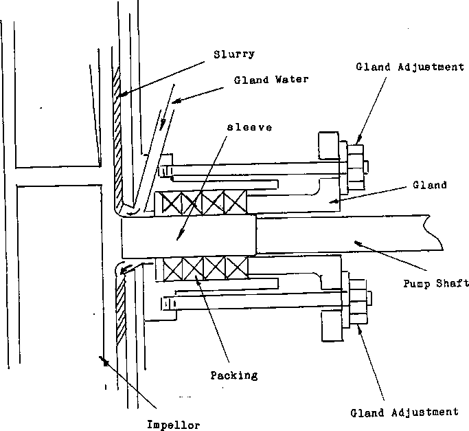
The packing material forms a seal that prevents slurry from escaping from around the IMPELLER SHAFT. This is the shaft that the impeller is screwed onto and turns with the impeller. To make this seal workable, three things were required.
First to be able to maintain even pressure between the shaft and the packing material, a method of adjustment was required.
A collar was designed to-go around the shaft and protrude into the stuffing box far enough to be able to put pressure onto the packing material when tightened down. The pressure against the packing will cause it to bulge, putting pressure onto the shaft. The degree that the collar, or GLAND as it is called, is tightened down, dictates the pressure that is on the shaft.
Secondly due to the expense of impeller shafts, a portion of it was designed to be replaced. This portion is called the SLEEVE. This is simply a collar of metal that the packing material forms a seal against. This seal often gets grit and dirt in between the packing and the sleeve causing a great deal of abrasion. When this happens the replaceable sleeve will be worn out, not the expensive shaft.
The third item that was needed was a method to equalize the head pressure, of the pump, on the packing material in the stuffing box. This pressure will force the ground rock that is in the slurry in between the packing and the sleeve. In this case a water line was attached to the stuffing box. Its discharge point is directly in front of packing and forms a water seal around the moving shaft. This clean water is added at a pressure as great as or greater than the pressure generated by the pump. Because of this pressure, the grit cannot force itself through the clean water to contaminate the packing. This water is called GLAND WATER.
To help reduce heat and provide a measure of lubrication for the packing, a properly adjusted gland will allow a very small amount of water to flow between the packing and the sleeve. This bit of water will lubricate the packing and help prevent wear.
SRL PUMPS AT PIMA MINING COMPANY
Pima Mining Company, at Tucson, Arizona, was the first new copper mill designed to classify entirely with cyclones.
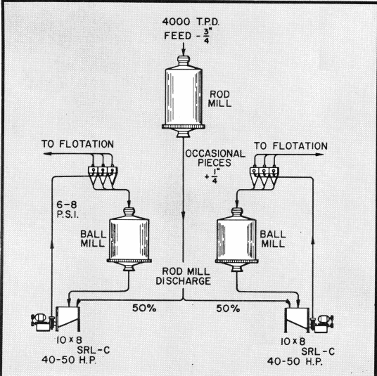
At Pima, duplicate 10″ x 8″ SRL-C Pumps handle the discharge from one ball mill plus 50% of the rod mill discharge. The rod mill discharge contains pieces as large as ¼” occasionally.
Each pump delivers 1200-1600 g.p.m. pulp at 55%-60% solids to the cyclone classifiers. Screen analysis of pump feed is:

Each 10″ x 8″ SRL-C Pump feeds three 20″ cyclones. The cyclones have an inlet pressure of 6-8 pounds and use a 3¼” apex and a 6¾” vortex. Pumps operate against a total dynamic head of 34′ and draw 40-50 HP. A portion of the cyclone overflow is bled off to maintain a constant sump level.
Pima’s SRL Pump Runners average better than 7 months service and handle more than 300,-000 tons. In addition to the SRL Pumps in the grinding circuit there are seven other SRL Pumps in this large copper mill.
https://www.911metallurgist.com/srl-pump-parts

