Table of Contents
- Thickener Design
- The Four Settling Zones
- Slimes Classified as to Settling Rate
- Type 1 of Settling
- Type II of Settling
- Formula for Determining Capacity of Continuous Thickeners
- Thickening in Zone D and Consistency of Discharge Possible
- Summary of Slime-Settling Results
- To Ascertain the Necessary Depth of Tank
- Method of Making Settling Tests
- Special Apparatus for Small-Scale Continuous Settling Tests
- Remarks Concerning Settling Tests
In order to develop rational methods of measurement and laboratory testing, it becomes necessary to study the general phenomena of settling rates. Since it was desired to give the public the benefit of these methods at as early a date as possible, together with the knowledge of the general principles of slime settling necessary for a clear understanding of the laboratory tests, we have ventured to discuss the subject in so far as brought out by the work which we now have under way. We realize that certain of our preliminary conclusions may be subject to modification, but it seems probable that, with but few exceptions, the general laws enunciated will cover the settling behavior of all pulps encountered in metallurgical plants. However, it must be recognized that there is still a vast amount of work to be done upon certain phases of the subject; therefore, at this time we will attempt only a discussion of the behavior of ore pulps during the process of settling or dewatering, under certain given conditions.
Thickener Design
The laws and principles controlling these conditions are not fully established, so that a complete discussion of them will not be attempted in this paper. In metallurgical practice, slime pulp consists of water, finely divided sand or granular particles, and colloidal material. In this connection water is used as implying either ordinary water or water containing some chemical or chemicals in solution. The chemical or chemicals present which exert an influence upon the subsequent settling behavior of the pulp are known as electrolytes. The electrolyte has the property of causing the colloidal portion of the slime to form aggregates known as floes, particles having a more or less definite size, consisting of water, colloidal material and usually fine granular material which has been entrapped. The floes settle in the liquid medium according to certain laws.
The Four Settling Zones
If a thin pulp, of a dilution of, say, 10 to 1, is placed in a 1,000 c.c. cylinder, after thorough mixture, at least momentarily, it forms a homogeneous mass, as shown in Fig. 1(E).
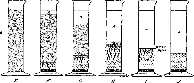
Fig.1- Experiment Showing Various Stages of Slime-Settling
After a short time, however, it assumes a flocculent structure which, after settling a brief period of time, forms four distinct zones (A, C, and D), as indicated in Fig. 1 (F). The first particles that reach the bottom of the cylinder are the coarser granular sand which may be present in the pulp. Immediately following this and somewhat contemporaneously with the settling of the sand, the slime flocs nearest the bottom settle, filling the interstitial spaces between the sand particles, and build up, one upon another, in a zone of increasing depth. This we term zone D, which may be defined as that portion of the pulp wherein the flocs, considered as integral bodies, have settled to a point where they rest directly one upon another. After pulp enters zone D, further separation of liquid must come through liquid pressed out of the flocs and out of the interstitial spaces between the flocs. Immediately above zone D is a transition zone C. The pulp in zone C decreases in percentage of solids from the bottom, where the flocs enter zone D, to the top, where the consistency of the flocculated pulp is the same as that of the original pulp. In speaking of flocculated pulp, it is intended to eliminate from consideration the coarser portion of the contained sand which falls directly through the overlying zones into zone D. Above C is zone B, of constant consistency of flocculated pulp and of the same consistency as the flocculated pulp in the feed pulp. Zone A, overlying zone is clear water or solution. In the case of a very rapidly settling slime, particularly with material which has been roasted, zone A in the earlier stages may be turbid, due to finely divided matter remaining in suspension. Later this very fine material settles and the liquid becomes clear, although there are cases, especially when the liquid contains very little electrolyte, where it remains turbid for a long time.
The effect of the relations between the depths of zones B and C upon curves derived from settling tests will be discussed later.
Fig. 1 (E) shows a cylinder freshly filled with pulp of a consistency of about 10 parts water to 1 part ore. In this illustration zone B occupies the total depth. F, G, and H of Fig. 1 show progressive stages of settling in which zones A and D are growing deeper, zone B is decreasing in depth, and zone C remains constant—a feature of this particular pulp. Fig. 1 (I) shows the condition when all of the pulp has entered zone D and compression of the slime flocs is going on. Fig. 1 (J) shows the final stage of settling, beyond which the pulp will not thicken further.
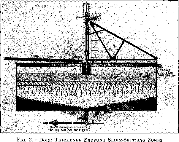
With intermittent operation, any one of the stages described may represent the condition in the thickener, depending upon the length of time that the pulp has been allowed to settle. In the operation of continuous thickeners, the feed of the thin pulp at the center of the tank, the overflow of clear liquid at the periphery of the tank, and the discharge of the thickened pulp at the bottom, are generally continuous. In a continuous thickener, the four zones previously described in discussing intermittent settling are generally present as shown in Fig. 2. At the top there is a zone of clear water, A. Beneath this is zone B, consisting of flocculated pulp of uniform consistency. Directly beneath this is a transition zone, C, and at the bottom a zone, D, of pulp which is undergoing compression.
In making tests, the settling rates of thin pulps are determined by readings taken at the juncture of zones A and B, i.e., where the pulp surface joins the clear liquid.
We designate as free settling pulp all of the pulp in zones B and C wherein the sand and flocs are falling freely through the liquid without pressing on the layers of floes beneath, although it is evident, from the peculiarly interlocking structure of flocculated pulp, that there are points of contact between the flocs even in these zones.
Critical Settling Point Defined:
We designate as the Critical Settling Point the top of zone D just as zone C disappears. At this point the flocs at the surface just rest upon each other, but compression has not yet commenced in the surface layer. It is therefore obvious that any elimination of liquid from zone D cannot be accomplished by free settling but must be effected by compression of flocs. The water liberated by compression finds its way out of zone D through tubes or channels which form drainage systems upward through the zone. The trunk channel for any system has its outlet at the top of zone D.
Since zone B, Fig. 1 (E, F and G) is made up of flocculated pulp of constant-consistency, the flocs in this zone will settle at a constant rate so long as the zone exists.
If zone C remains shallow and of constant depth, the liquid being expelled from zone D may be ejected through zone C with little admixture with this zone. This upward current of liquid which has diffused through zone B during the first stages of settling may also be ejected through zone B, when B becomes very shallow, and thereby considerably increase the apparent settling rate of the pulp at this stage. This does not indicate that during this period more pulp passes into zone D, It is merely a surface phenomenon, indicating that zone C is very shallow.
A curve plotted from the results of a settling test such as is illustrated in Fig. 1 will show a constant settling rate throughout the stages represented in Fig. 1 (E, F and G), an increased rate when the stage shown in Fig. 1 (H) is reached, followed by a rapid retardation in the settling rate after zone B disappears, until zone C has also disappeared. Following this is a very slow rate of settling which gradually becomes slower as the water is compressed from zone D. The final stage of settling is reached when no further liquid is expelled from zone D by compression. The later stages of settling are shown in Fig. 1 (I and J).
Slimes Classified as to Settling Rate
The type of settling showing a constant rate down to near the critical point, regardless of whether acceleration is manifested or not, we term
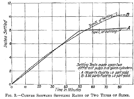
Type I. This is illustrated in Fig. 3 by curve A. With certain pulps a constant rate of settling does not occur, since zone C rapidly reaches the surface. The surface of such a pulp contained in a cylinder, therefore, settles at a continually decreasing rate down to the critical point. We term this type of settling Type II. It is illustrated by curve B, Fig. 3.
Type 1 of Settling
A pulp containing very little sand was mixed with water containing 40 points of lime (100 points being equivalent to a saturated solution of lime in water, i.e., 0.13 per cent.) to give a pulp of a consistency of 5,7 parts of liquid to 1 part of ore. This pulp settled at a constant rate to near the critical point. Tests were also made to ascertain the settling rates of pulps of 4.71 and 4.00 parts of liquid to 1 part of ore, respectively.
Consistency of Pulp Parts water to 1 Part Ore | Rate of Settling Feet Per Hour | |
| I | 5.7 | 0.6 |
| II | 4.71 | 0.464 |
| III | 4.00 | 0.414 |
Conceive a column of pulp consisting of three distinct layers: I (upper), II (middle), and III (lower), having consistencies of 5.7, 4.7 and 4.00 parts fluid to 1 part solids, respectively, layer I feeding into layer II, and layer II feeding into layer III. Let it be assumed that the liquid contained in the flocs and being carried down with them is 3 parts to 1 part of solids. Since the flocs in the three layers are passing downward at known rates, we may compute the weight of solids being fed from a given area of each layer per unit of time, i.e., from layer I to layer II, from layer II to layer III, and leaving layer III, as follows: The pulp in layer I consists of 5.7 parts fluid to 1 part of solids, making a total of 6.7 parts. Of this, 3 parts fluid and 1 part solids are passing downward while 2.7 parts of fluid remain behind. Therefore, for each 2.7 parts of fluid which remain behind, 1 part of solids passes downward and out of layer I. Since the pulp in layer I settled at the rate of 0.6 ft. per hour, the water remaining behind in an area of 1 sq. ft., in 1 hr. would be 0.6 cu. ft., equivalent to 37.41 lb. (water weighs 62.35 lb. per cubic foot) and the weight of solids passing out of layer I per hour would be 13.8 lb. per square foot. In a similar manner it is calculated that the solids passing out of layer II are 16.9 lb. per square foot per hour and the solids passing out of layer III are 25.8 lb. per square foot per hour. The following table shows the weight of solids, in pounds, which may be fed from each layer, assuming the quantity of fluid carried downward in the floes to be as follows: 1 part fluid to 1 part solids; 2 parts fluid to 1 part solids; 2½, parts fluid to 1 part solids: and 3 parts fluid to 1 part solids.
| Layer | 1 to 1 Pounds | 2 to 1 Pounds | 2½ to 1 Pounds | 3 to 1 Pounds |
| I. | 7.95 | 10.1 | 11.6 | 13.8 |
| II. | 7.78 | 10.6 | 13.1 | 16.9 |
| III. | 8.60 | 12.9 | 17.2 | 25.8 |
It will be noted that if the flocs are assumed to contain between 2 to 1 and 3 to 1 parts of liquid, the weight of solids passing out of layers II and III will be greater than the weight passing into each from the overlying layer. Therefore, layers II and III must decrease in depth, and finally become infinitely shallow. The rate of settling will therefore remain constant in a settling test on the pulp of the consistency of 5.7 parts liquid to 1 part solids, until the pulp becomes thicker than that in layer III. If the flocs contained only 1 part liquid to 1 part solids, layer II would increase in depth and in a continuous settling test the rate of settling would decrease until the rate of 0.464 ft. per hour was reached and thereafter would remain constant until all of the pulp became thicker than that in layer III. Since investigation shows that the settling rate remains constant almost to the critical point, the proportion of liquid in the flocs must be greater than 1 to 1.
Type II of Settling
Fig. 3 (B) is the curve plotted from the results of a continuous settling test made upon a pulp showing Type II settling. This pulp showed a very fine flocculated structure. The consistency was 5.92 parts fluid to 1 part solids. It was placed in a 1,000 c.c. cylinder and allowed to settle without interruption to the critical point. Readings were taken at intervals and the settling rates in feet per hour were computed.
After permitting the sand to settle out of a sample of this pulp, it was found that the free-settling sand represented 46 per cent, of the total solids. Settling rates were determined on pulps of varying consistencies. The consistencies are estimated as the ratio of fluid to total solids (1) and as the ratio of fluid to flocculated solids (2). The consistencies and settling rates are given below:
| Layer | Ratio of Fluid to Total Solids (I) | Ratio of Fluid to Flocculated Solids (2) | Rate of Settling in Feet per Hour |
| I. | 5.92-1 | 10.95-1 | 1.03 |
| II. | 5.17-1 | 9.57-1 | 0.89 |
| III. | 4.42-1 | 8.20-1 | 0.69 |
| IV. | 3.67-1 | 6.79-1 | 0.52 |
| V. | 3.17-1 | 5.87-1 | 0.417 |
| VI. | 2.92-1 | 5.40-1 | 0.372 |
| VII. | 2.42-1 | 4.48-1 | 0.297 |
| VIII. | 2.00-1 | 3.70-1 | 0.248 |
Using the same line of reasoning that was followed in estimating the settling capacities through the various layers in discussing Type I of settling and estimating the amount of fluid contained in the floes at 2 parts fluid to 1 part flocculated slime and also at 3 parts fluid to 1 part flocculated slime, the following capacities are obtained in pounds per hour of flocculated slime which may pass out of each respective layer:
Layer | Flocs Containing 2 to 1 | Flocs Containing 3 to 1 |
| Pounds | Pounds | |
| I. | 7.16 | 8.06 |
| II. | 7.32 | 8.43 |
| III. | 6.93 | 8.26 |
| IV. | 6.75 | 8.55 |
| V. | 6.70 | 9.00 |
| VI. | 6.81 | 9.63 |
| VII. | 7.50 | 12.58 |
| VIII. | 9.12 | 22.40 |
If we assume that the flocs are made up of 3 parts fluid to 1 part flocculated solids, the estimated weight of solids passing out of each layer appears to be greater than the amount fed into it from above. In this event the lower layers could not exist and the settling would, therefore, follow Type I. If we assume flocs made up of 2 parts fluid to 1 part solids, the estimated weight of solids passing out of each layer (eliminating the settling rate in II, which was probably erroneous) into the layer below becomes less than the amount fed into it down to layer VI, after which the quantity of solids passing out of each layer is greater than the weight fed into it from above. In this case layers V, IV, III, etc., would increase in depth as layers I, II, etc., disappear, and the settling rate indicated by a continuous settling test made in a cylinder, filled with pulp similar to that in layer I, will decrease continuously until the pulp at the surface is of a consistency between that of the pulp in layers V and VI. Layers VI to VIII will be infinitely thin, since it is possible for more pulp to pass out from each layer than the amount which enters it and, therefore, the settling rate of pulps of the consistencies contained in these layers will only appear in a period of rapid transition from the settling rate in layer V to the settling rate in some layer below VIII, It has been calculated, from the data from which curve B (Fig. 3) was plotted, that the rate of settling decreased in 66 min. from 1.03 ft. per hour, as in layer I to 0.55 ft. per hour, and in the next 18 min. dropped to 0.08 ft. per hour. From the above it should be evident that the weight of solids which can pass from each layer is dependent upon the percentage of sand present (which passes downward carrying no liquid), upon the ratio of fluid to solids in the flocs and upon the settling rate of the pulp in the layer considered. The capacity of a layer of any consistency of flocculated pulp to discharge its flocculated solids may be calculated by the following formula:

c = capacity in pounds of flocculated solids per square foot per hour.
r = settling rate in feet per hour in the layer.
f = ratio of fluid to flocculated solids in the layer.
d = ratio of fluid to flocculated solids in the flocs.
62.35 = weight of 1 cu. ft. of water.
In the illustration of Type II of settling, pulp of a consistency of 3.17 parts fluid to 1 part solids or 5.87 parts fluid to 1 part flocculated solids settled at a rate of 0.417 ft. per hour. Assuming that the flocs contain 2 parts fluid to 1 part solids, the above formula gives ![]() lb. per square foot per hour of flocculated solids and 13.4 lb. of fluid passing downward out of layer V, but since the flocculated solids represent only 54 per cent, of the total solids, the total weight of solids passing downward out of layer would be 12.4 lb. per square foot per hour. The proportion of fluid carried down in the flocs to total solids would be 13.4 : 12.4 :: 1.08 : 1. Given the ratio of fluid to total solids in a pulp with a known settling rate and the ratio of fluid to total solids to be discharged, it is not necessary to know the percentage of fluid in the floes in order to determine the maximum capacity of such a layer of pulp to discharge pulp of the consistency required. Thus in the above case the ratio of fluid to total solids equals 3.17 to 1, and the ratio of fluid to solids in the discharge required is 1.08 to 1. Applying the formula, we find c =
lb. per square foot per hour of flocculated solids and 13.4 lb. of fluid passing downward out of layer V, but since the flocculated solids represent only 54 per cent, of the total solids, the total weight of solids passing downward out of layer would be 12.4 lb. per square foot per hour. The proportion of fluid carried down in the flocs to total solids would be 13.4 : 12.4 :: 1.08 : 1. Given the ratio of fluid to total solids in a pulp with a known settling rate and the ratio of fluid to total solids to be discharged, it is not necessary to know the percentage of fluid in the floes in order to determine the maximum capacity of such a layer of pulp to discharge pulp of the consistency required. Thus in the above case the ratio of fluid to total solids equals 3.17 to 1, and the ratio of fluid to solids in the discharge required is 1.08 to 1. Applying the formula, we find c = ![]() which is the same as that given above. The formula may, therefore be written
which is the same as that given above. The formula may, therefore be written ![]() where’
where’
F = ratio of fluid to solids in the pulp tested.
R = rate of settling in feet per hour of a free-settling pulp of consistency F.
D = ratio of fluid to solids in the discharge required.
C = capacity in pounds of solids per square foot per hour, which may be discharged with a consistency of D from a layer of pulp of a consistency of F settling at a rate R.
Formula for Determining Capacity of Continuous Thickeners
Since in any vessel used for settling there are layers of pulp of every consistency between that of the feed and that of the discharge, although some of the layers may be infinitely shallow, the maximum capacity in pounds of solids per square foot per hour is expressed by the formula ![]() and the maximum capacity possible will be the smallest value of C obtained by applying this formula to a series of tests made upon pulp ranging in consistency from that of the feed to that of the thickest free-settling pulp, and taking for D the ratio of fluid to solids desired in the discharge.
and the maximum capacity possible will be the smallest value of C obtained by applying this formula to a series of tests made upon pulp ranging in consistency from that of the feed to that of the thickest free-settling pulp, and taking for D the ratio of fluid to solids desired in the discharge.
Thickening in Zone D and Consistency of Discharge Possible
We have established through numerous experiments the fact that after pulp reaches the consistency where the floes touch each other, further elimination of water becomes approximately a function of time, in so far as tests for metallurgical practice are concerned. It seems probable that the
relationship of pulp consistency to time of thickening is an indirect one, depending upon the effect of compression caused by the depth of the pulp being counteracted by the resistance in the pulp to the escaping water, and to the admixture of the pulp in the upper portion of the thickening layer with the ascending water from the lower layers. A large number of comparative tests have been made in vessels of from 1 to 10 ft. in depth. If portions of pulp be placed in vessels of various depths, it will be found that the critical point will be reached earliest by the surface of the pulp in the most shallow vessel, since the pulp does not have so far to settle to reach the zone of compression (D), but the settling rates in layers of like consistency are the same for vessels of all depths. In the deep vessels the critical point will be proportionately lower than in the shallow vessels. This may be explained by the fact that the average time of compression in the thickening zone before the critical point is reached is greatest for the pulp in the deep vessel. If the fluid be expelled as a function of time after the flocs enter the zone of compression, it is but natural that this should be the case.
In two vessels of unequal depth, filled with the same kind of pulp and started to settle at the same time, the total pulp in the more shallow vessel will begin to compress more quickly and will thereafter for many hours remain thicker than the pulp in the deeper vessel, even though the critical points occur not more than an hour apart. This indicates that thickening in the compression zone is a function of time. In one or two cases it was noted that after a time pulp in the deeper vessel became the thickest, but, upon decanting the fluid from the pulp contained in the shallow vessel and stirring the remaining pulp, settling was resumed until the pulp was as thick or thicker than that in the deeper vessel. We assume that this difference was due to the fact that most of the sand in the shallow vessel reached the bottom, while in the deeper vessel some of the sand lodged in the lower part of the compression zone and assisted compression.
Another series of tests was made by placing moderately thick pulp in cylinders of various depths. It was found that after allowing time for the structure to develop and channels to form in the deep cylinder, the total settling at various periods of time was approximately proportional to the depth of the cylinder. There is, however, a limit to this, for it appears that as the settling by compression in a deep vessel reaches the slowest settling rate for free-settling pulp, a zone of semi-thickened pulp will be formed and maintained until the compression rate for the total column slows down to a lower rate than the lowest free-settling rate of the pulp. In this series of tests the greatest consistency for various periods of time is almost invariably reached in the most shallow cylinders, but the difference is slight and to a great extent due to the resistance of the pulp to liquid rising from the bottom of the cylinder. In practice in continuous thickening, such a zone of semi-thickened pulp never reaches the bottom of the tank, since large amounts of fluid do not have to be liberated from the pulp at the bottom. This resistance is therefore of less consequence in practical operation.
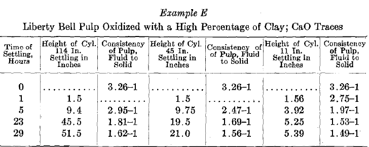
The diameter of the cylinder or tank used for making the test seems to have little or no influence upon settling. Tests made upon various pulp samples in cylinders varying in diameter from ½ in. to 2½ in. show very slight differences in the settling rates and in the final consistency of the settled pulp. The 1/2-in. tube generally gave a more rapid rate of settling down to the critical point, probably due to convection currents. Beyond this point, the pulp in the tube of small diameter settles more slowly. The following experiment will illustrate this point: A 4-ft. cylinder, 2½ in. in diameter, and a 4-ft. cylinder, ½ in. in diameter, were filled with Liberty Bell pulp, 3.26 parts water to 1 part dry slime. The water contained 4 points of lime. The consistency of the settled pulp, after settling 48 hr. in the 2½-in. cylinder was 1.8 parts water to 1 part of dry slime, while in the ½-in. cylinder it was 1.825 parts water to 1 part dry slime. It was found that the difference was greater when the water contained a greater proportion of electrolyte (in this case, lime), for the reason that as the proportion of electrolyte is increased, the slime flocs become larger and agglomerate in such a manner as to offer more resistance to settling in the small cylinder. With a large proportion of lime, the pulp in the small cylinder settled in divisions, due to the arching effect of the large slime flocs, there, being alternate layers of clear liquid and of thick pulp. It was noted that ultimately the sum of the zones of clear liquid equaled the total depth of clear liquid formed in the larger cylinder. All of our tests have indicated that if the diameter of the cylinder is 2 in. or over, little or no influence is exerted upon the rate of settling.
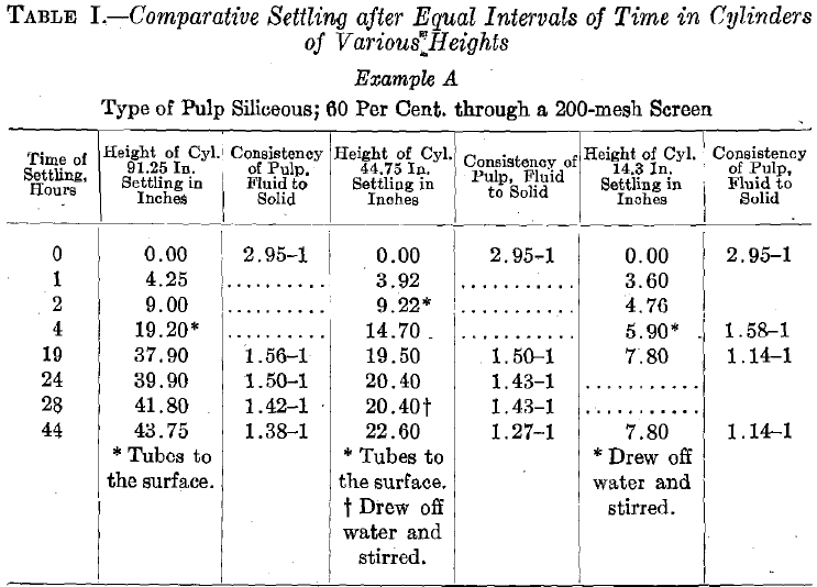
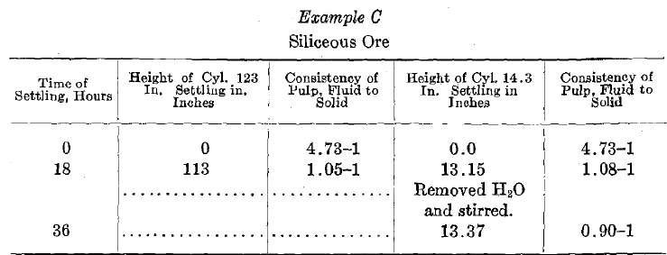
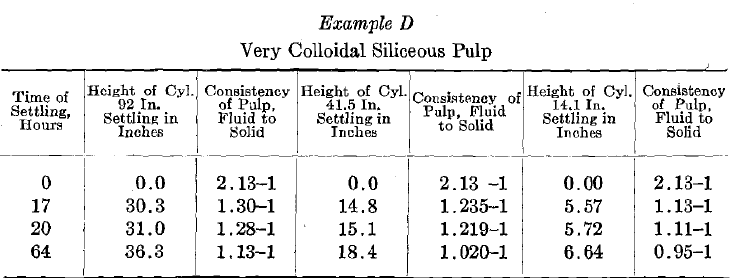
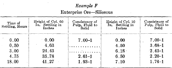
Table I gives the record of some of the tests made to establish the fact that ultimate consistency of the pulp is a function of the time during which the pulp remains in the thickening zone. The names of the mines from which these pulps came are not given, as permission to publish them was not obtained. Example G in Table I was made on a pulp consisting of 6 parts solution of zinc sulphate containing hydrogen sulphide to 1 part precipitated barium sulphate and zinc sulphide. Despite the low percentage of solids, the pulp is very viscous and is not free settling. Air bubbles remained entrapped for 36 hr. when the pulp was allowed to settle in a cylinder 16 in. in depth. In a cylinder 66 in. in depth the bubbles were ejected and the settling rate became 50 per cent, greater than the ratio of the depth to that of the lower cylinder would indicate. It would seem that in this type of pulp the law of compression being a function of time would not hold. Apparently the reason is that the highly viscous homogeneous structure resists the formation of tubes and channels in zone D, except under higher pressure through a deeper column of pulp. It is possible that with a large proportion of electrolyte, for instance, lime, certain ore pulps also may behave in this manner. When such cases arise, recourse must be had to the test described later in the paper. Such a condition is generally indicated by the absence of the ordinary flocculated structure and the fact that active channeling does not take place in zone D.


Summary of Slime-Settling Results
The results of our investigation of slime settling may be summarized as follows:
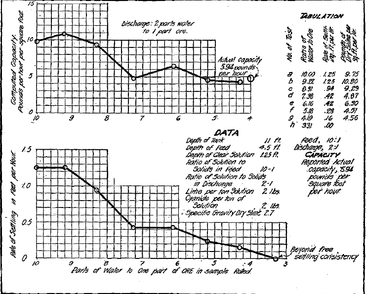 Fig. 4- Slime-Settling Data, Liberty Bell Mill, Telluride, Col.
In thickening pulps which are to be discharged at a consistency such that the discharge is still in the form of free-settling pulp, the depth of the tank used is of no consequence, except in so far as it permits a depth of feed sufficient to avoid surface agitation and allows ample depth of clear liquid to care for fluctuations of the feed and changes in the character of the pulp in the case of continuous thickeners, and sufficient depth to give ample capacity to avoid the necessity of frequent charging and discharging in the case of intermittent thickeners.
When thickening pulps to a consistency where it is necessary to expel fluid by compression, sufficient capacity must be given the tank so that the pulp will be retained the necessary period of time to thicken it to the required density and also to allow sufficient storage to compensate for fluctuations in the feed and discharge. This capacity may be obtained by varying either the depth or diameter to give the required cubical content.
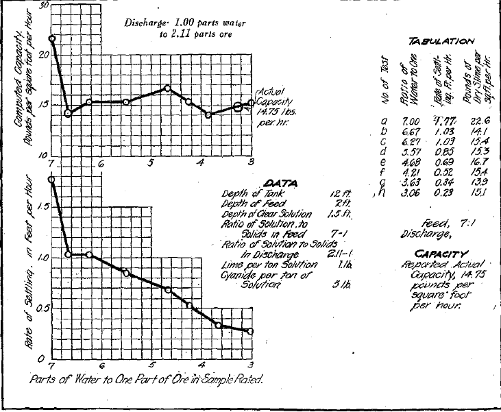 Fig.5- Slime-Settling Data, Belmont Mill, Tonopah, Nev.
The consistency of discharge possible may be closely determined by allowing a cylinder of thick but free-settling pulp to settle, taking readings at intervals of a few hours up to the point where settling practically ceases.
The required area may be computed by applying the formula  A is the area in square feet required to thicken 1 ton of 2,000 lb. of solids to a, consistency in the discharge of D (parts fluid to 1 part solids by weight), per day of 24 hr. A series of settling rates is taken on pulps ranging in consistencies from that of the proposed feed to the thickest free-settling pulp. D is taken as the ratio of fluid to solids in the thickest pulp which can be economically obtained. The greatest value for A indicated by the tests is taken as the required area. Under ordinary circumstances a factor of safety should be allowed over the calculated area to take care of changes in the character of the pulp and variations in temperature. It will be noted that this is the same formula previously
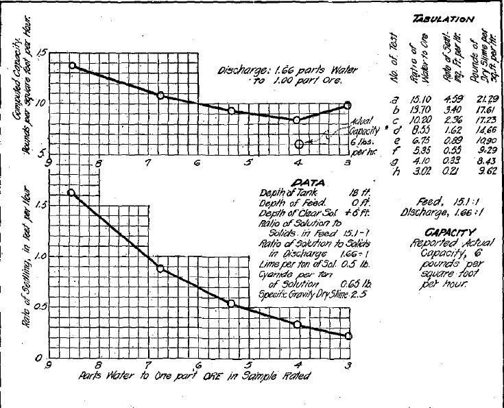
Fig.6- Slime-Settling Data, Portland Mill, Victor, Col.
given, modified to give area required instead of capacity per square foot per hour.
The required depth of the thickener may be ascertained by computing the capacity of the thickening zone to contain a supply of solids equal to the total capacity of the tank for the number of hours required to thicken the pulp to the density required in the discharge, and to this depth adding an allowance for the lost space due to the pitch of the drag in the thickener; also from 1½ to 2½ ft. for depth of feed and a further allowance for storage capacity when the discharge may be closed. The following is an illustration of the method used in computing the area and depth required in a thickener to handle 100 tons of pulp per day, thickening from 6 parts fluid to 1 part solids down to 1.12 parts fluid to 1 part solids.

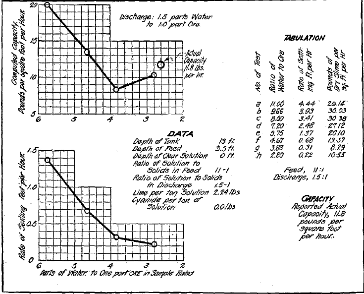 Fig.7- Slime-Settling Data, Nipissing Low-Grade Mill, Cobalt, Ont.
The formula  was applied to ascertain the above areas. Taking for instance the third test, R = 0.893, F = 4 D = 1.12, then
  the number of square feet required per ton per day. For handling 100 tons per day, 431 sq. ft. or the area of a tank 23.4 ft. in diameter would be required. In the above example the third test is taken for the required area as being the largest area indicated by any of the tests while the areas indicated by the fourth and the fifth tests show that the areas are diminishing for the thicker pulps therefore the turning point has been passed.
To Ascertain the Necessary Depth of Tank
Assuming that the following results are obtained from settling tests made in a cylinder 12 in. deep upon 3 to 1 pulp, the computations are made as follows:
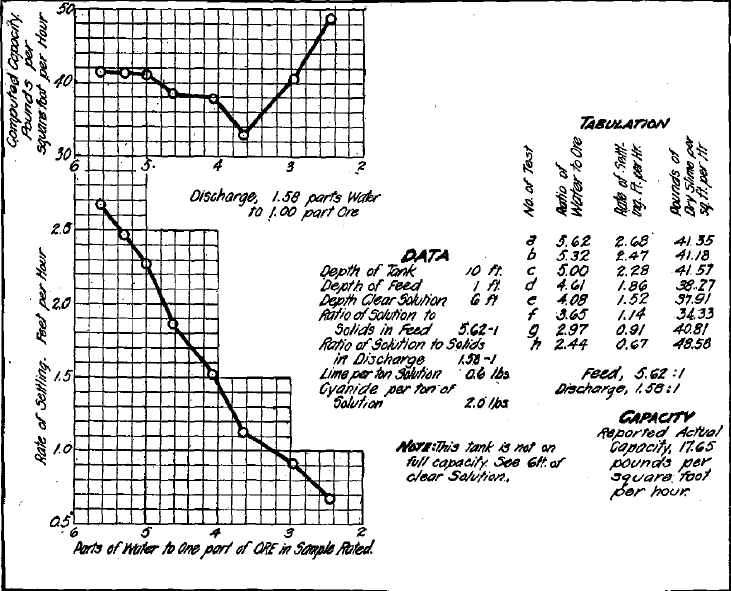 Fig.8- Slime-Settling Data, Presidio Mill, Shafter, Tex.
| Time of Thickening Hours | Consistency Fluid to Solids |
| 2 | 1.70:1 |
| 4 | 1.59:1 |
| 9 | 1.35:1 |
| 14 | 1.20:1 |
| 19 | 1.12:1 |
Since an area of 4.31 sq. ft. is required per ton of solids per 24 hr., the total solids per square foot retained in the thickening zone must be 19 x 2000 / 24 x 4.31 = 367 lb or 19 hours supply per square foot. There is required a 5-hr. supply of each of the pulp consistencies 1.16 to 1:1.275 to 1:147 to 1 and a 4-hr. supply of a 1.7 to 1 pulp. The solids per cubic foot in the above pulps are 43.2 lb., 37.6 lb., 33.7 lb. and 30 lb., respectively. The depth of each class of pulp would therefore be 2.23 ft., 2.57 ft., 2.87 ft., and 2.58 ft., or a total depth of 10.25 ft. To this depth must be added a foot for the loss due to the pitch of the drags in the thickener and 1.5 ft. for the depth of the feed, since the feed is thick and the volume will be proportionately low. The total calculated depth of the tank required would be 12.75 ft. If proper allowance were made for storage capacity, the tank might be inconveniently deep.
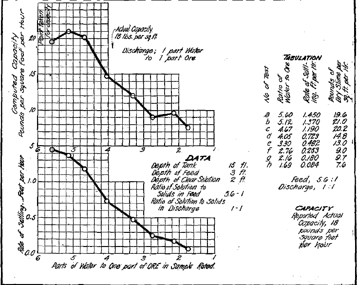
In this case it would be better practice to make the tank 12 ft. deep and make various allowances for additional capacity by increasing the diameter of the tank to give a 30 per cent. increase in area, Ordinarily in settling ore pulps composed of fine granular material with a considerable proportion of colloidal material which may vary in character, it is unwise to provide less than 6 sq. ft. of settling area per ton of solids to be settled daily. Frequently much larger areas are required.
If, in the tests previously cited, the fourth and fifth settling rates had decreased so as to cause the indicated required areas to increase gradually, the solution of the problem would be less simple, for it is necessary to be certain that the settling rate for the thickest free-settling pulp has been determined and also that the pulp being tested is free settling. Ordinarily the latter point is indicated by the evenly flocculated appearance of the pulp surface, without channels of fluid coming through, and by the uniform texture of the pulp as seen in a glass cylinder. The settling rate, after flocculation is complete, should be constant or gradually diminishing to the critical point. In certain thick, free-settling pulps containing a large proportion of electrolyte, the whole mass agglomerates upon shaking, and in a shallow cylinder the time required to form the natural structure will be so great that the pulp will have passed the critical point before a reliable settling rate has been observed.
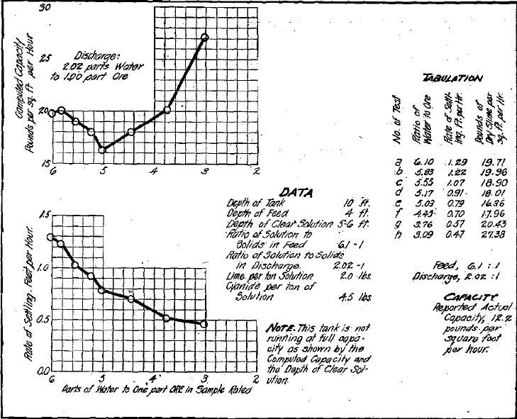 Fig.-10 Slime-Settling Data, West End Consolidated Mill, Tonopah Nev.
In such cases the series of tests should be repeated using less electrolyte, the object being to ascertain the consistency at which the indicated area establishes itself as a constant, or decreases. Should it not be feasible to reduce the proportion of electrolyte, cylinders 3 or 4 ft. in height may be employed in repeating the tests, in order that sufficient time may be given for the flocculated structure and even texture to become apparent. If, after applying these tests, it is desired to verify the results still further, it becomes necessary to make a test representing actual continuous feed and discharge conditions, as hereafter described in this paper.
In making settling tests the sample should be carefully taken in order that it may be truly representative of the pulp to be settled. The ratio of fluid to solids may be determined by drying a sample from each test. The pulp is placed in a 1,000 c.c. cylinder and well shaken; it is then allowed to settle. Readings should be taken at intervals of from 1 to 3 min. until the pulp has reached a uniform or decreasing settling rate, the maximum rate being taken as the one sought. The readings are most conveniently taken in cubic centimeters and the settling rate in feet per hour may be computed from these by establishing the value
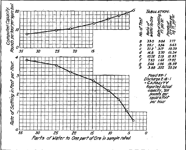 Fig.11- Slime-Settling Data, Homestake Mill, Lead S.D.
in decimal parts of a foot of each cubic centimetre. This is done by measuring, in feet, the length of the 1,000 c.c. graduation on the cylinder and dividing by 1,000.
Method of Making Settling Tests
The method of making the settling tests hereafter quoted was as follows: In each case the pulp was permitted to settle 1/8 in. before the readings were taken.
(a) 1,000 c.c. feed pulp settled for a 2-min. interval.
(b) After completing test (a) and thoroughly mixing by shaking 25 c.c. of pulp was removed from the cylinder and replaced by 25 c.c. of discharge pulp. After thoroughly mixing, allowed to settle for an interval of 2 min.
(c) 30 c.c. of pulp removed from (6) and replaced by 30 .c.c. of discharge pulp, settling interval 2 min.
(d) 45 c.c. of pulp removed from (c) and replaced by 45 c.c. of discharge pulp, settling interval 3 min.
(e) 75 c.c. of pulp removed from (d) and replaced by 75 c.c. of discharge pulp, settling interval 3 min.
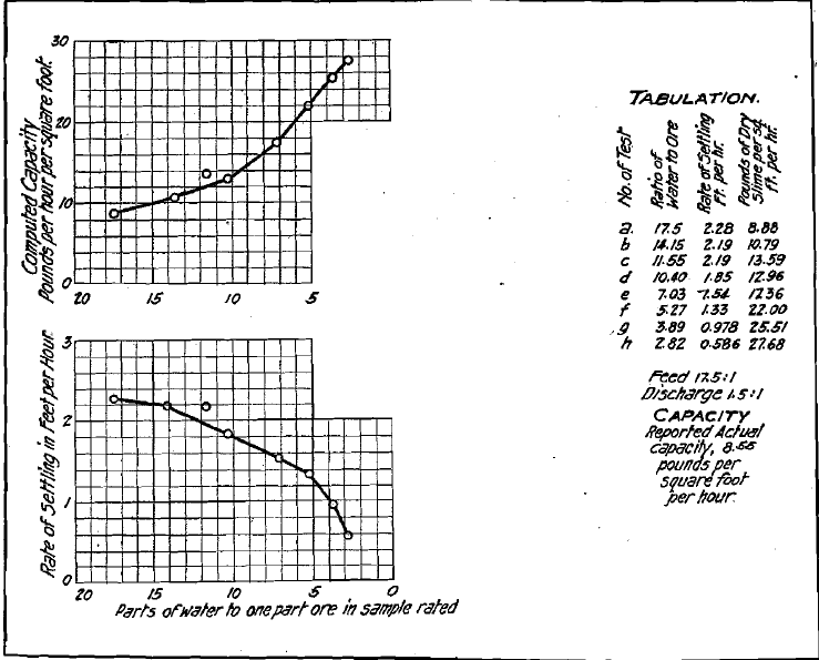 Fig.12- Slime-Settling Data, Homestake Mill, Lead S.D.
(f) 100 C.C. of pulp removed from (e) and replaced by 100 C.C. of discharge pulp, settling interval 4 min.
(g) 160 C.C. of pulp removed from (f) and replaced by 160 C.C. of discharge pulp, settling interval 4 min.
(h) 260 C.C. of pulp removed from (g) and replaced by 260 C.C. of discharge pulp, settling interval 6 min.
Throughout a series of tests the precaution must be taken of thoroughly mixing the contents of the cylinder both before removing pulp and before starting the test on the pulp of altered consistency.
The curves in Fig. 4, showing the settling behavior of Liberty Bell pulp, illustrate the method of plotting used in presenting the results of the tests which have been taken as a basis of comparison with the performance of commercial thickeners. In the lower curve the settling rate in feet per hour is taken as the ordinate, while the ratio of water to dry slime is taken as the abscissa. Each point shown on the curve represents an individual test made upon slime of the dilution noted. The tests appear upon the curve from left to right in the order performed which places the highest dilution at the origin.
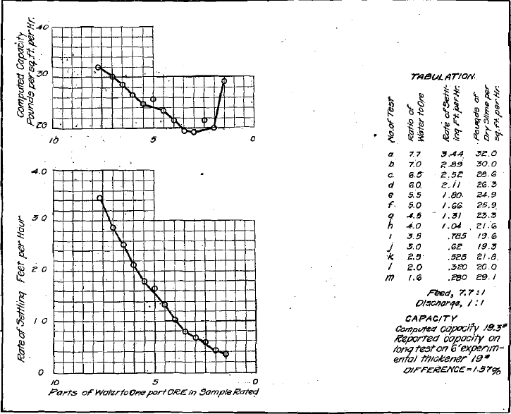 Fig.13- Slime-Settling Data, Golden Cycle Mill, Colorado Springs Col.
In the upper curve, the computed capacity in pounds per hour of dry slime per square foot of settling area is taken as the ordinate, while the dilution is taken as the abscissa, as in the lower curve.
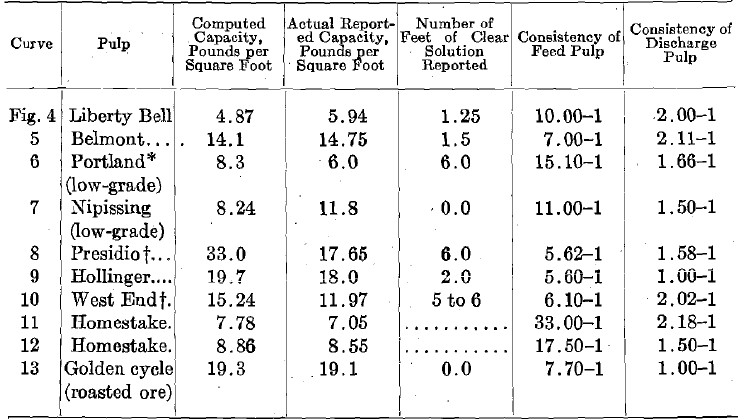
The following table gives the actual capacities, together with the computed capacities, of thickeners used at the various mills enumerated as shown in curves, Figs. 4 to 13, inclusive. In each case the tests were made at the mill by the local staff, according to directions supplied by us. From the data received the capacities were computed, employing the method described in the paper.
Special Apparatus for Small-Scale Continuous Settling Tests
Although, as demonstrated, reasonably accurate results may be obtained by settling tests made in small glass cylinders (provided the results are properly interpreted), we recommend for testing a special device in which tests may be carried out under the same conditions of depth as would obtain in practice. Since the diameter of the cylinder, if over 2 in., does not in any way affect the settling rate, it is possible to construct from standard iron pipe and fittings, available in most localities, a device which will give results exactly parallel to those to be expected in practice. Fig. 14 shows in detail such a device, which in our experimental work has given very satisfactory results. The body or container is a piece of 4-in. black, iron gas-pipe, threaded at both ends (galvanized iron pipe or fittings should be avoided )on one end of which is screwed a 4-in. pipe flange, while on the other end is screwed a special cast-iron cone. Into the bottom of this cone is screwed a ½-in. nipple and connected to this is a ½-in. iron plug cock, into which is screwed another ½-in. nipple to prevent spattering. If it is not possible to procure the cone-shaped casting for the bottom, the same effect may be obtained by plugging the bottom of the pipe and screwing the discharge valve into a hole tapped at the center of the plug. A thin sheet-iron cone is
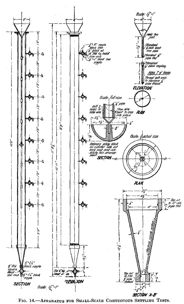
made of such a size that the top just fits the pipe, while the apex is of the same size as the hole in the plug. This cone is slipped inside of the pipe and downward until it rests upon the bottom. Along the side of the 4-in. pipe, at regular intervals of 12 in., are bored holes tapped for a ½-in. thread. Into each of these is screwed a ½-in. nipple, to which is attached a ½-in. plug cock; to this, in each case, is attached an elbow and nipple to divert the outflow downward. The 4-in. pipe is arranged with a tripod or other suitable means of support so that it is maintained in a vertical position at a sufficient distance from the floor for the thickened pulp to be withdrawn readily from the plug cock at the bottom. Resting on top of the main pipe or container is a funnel for introducing the pulp. Attached to this funnel by means of iron sleeves are 11-in. lengths of black iron pipe, the idea being to make each section, with the sleeve when screwed into position, 12 in. in length and so arranged that the outlet from the stem of the funnel is somewhat below the particular cock on the side of the apparatus in use. Any depth of feed in multiples of 12 in. may be obtained by screwing on to the funnel tube the necessary number of 12-in. units. To the lowermost unit in use is attached a cup-shaped iron casting for the purpose of distributing the flow of pulp. This may be an ordinary 2½-in. cast-iron drip cup, such as is frequently used beneath bearings, attached in such a manner as not to obstruct the outlet of the pipe. The apparatus shown in Fig. 14 has a maximum available depth of 9 ft. for the thickening zone. Therefore, settling tests may be performed in steps of 1 ft., representing what may be expected in tanks where the thickening zone varies from 2 to 9 ft. in depth. If a study of the behavior of deeper tanks is desired, a longer containing pipe may be employed. To illustrate the use of this piece of apparatus: Assume that the settling behavior of a given pulp and the capacity per square foot of settling area of a tank having a thickening zone 5 ft. in depth are to be determined. First make a preliminary settling test in a glass cylinder according to the directions previously given. Let it be assumed that the results are as follows: The critical point in the glass cylinder is ascertained to occur at a dilution of 3 parts fluid to 1 part solid and the mean settling rate down to this point is 1 ft. per hour. After these data are obtained, proceed with the large test as follows: Through the feed funnel introduce pulp of a consistency of 3½ parts fluid to 1 part solids, until the large containing tube is filled to 5 ft. Since in a 5-ft. column of 3½ to 1 pulp, ½ part water is equivalent to 7.65 in., it follows that this particular pulp must settle a distance greater than 7.65 in. before it reaches the critical point. Therefore, 1 ft. of feed with a consistency of, say, 7 parts fluid to 1 part solids, may be added to bring the pulp surface up to cock D6. After 1 hr., test the settling by opening cock D5 to ascertain if clear fluid can be withdrawn. Close cock D5 open cock D6 and pour feed in through the funnel until a murky overflow occurs at cock 06. Stop immediately the outflow at D6 by closing the cock. Allow another hour to elapse and test as before. Repeat this at hourly intervals until it is found that the pulp level has risen to cock D5, as determined by pulp flowing out at this cock. When this stage is reached, either the feed must be decreased or thickened pulp must be removed from the cock at the bottom. Next remove 6 in. of thickened pulp through the bottom cock. This pulp will be sandy and its specific gravity need not be determined. Feed may now be added at the original rate until pulp again appears at cock 05, when it becomes necessary to remove thickened pulp from the discharge cock. The amount of feed added should be ascertained by measuring the volume of both the overflow and discharge. Continue the process as described until the specific gravity of the discharge is uniform and the sand content normal. The feed pipe should extend slightly below the cock at the top of the zone tested and the surface of the pulp should never be permitted to fall below the mouth of the feed pipe, for, should it do so, it is not definitely known that the maximum feed is being given. If the pulp in the discharge is not as dense as desired, reduce the feed and continue the test. After equilibrium has been reached, the capacity per square foot per hour is computed. Further tests with various depths in the experimental apparatus will give the necessary data for choosing the depth of tank required. To the depth of thickening zone determined by the experimental apparatus must be added the additional necessary depth for storage, feed, etc., as previously explained; The series of tests for maximum capacity in the glass cylinder will greatly assist the operator in making the large tests.
Remarks Concerning Settling Tests
When we asked certain operators to make settling tests to prove the value of the formula C = 62.35 R/ (F-D) we were not familiar with the erratic behavior of certain thick pulps containing large proportions of lime, nor with the importance of small changes in temperature. We therefore limited the ratings to single readings on each test and did not mention the effect of temperature. I t is probable, in the few cases where a fairly close check between actual and indicated capacity is not shown when the thickeners were being worked to the limit of their capacity, that the discrepancy is due to one or the other of these causes.
In our earlier work the pulp samples tested were built up to give the desired consistency by combining the discharge and feed, as previously described. Subsequently it was found more convenient to start with a sufficient measured quantity of feed pulp and use the same pulp throughout the whole series of tests for maximum capacity, hence each pulp sample is now made up by decanting measured quantities of clear liquid and mixing the remaining pulp well before taking the sample for each test. A thorough mixture is very important, especially with tests which are to be settled for density. With thin pulps the settling rate will not be altered by the sand; for instance, if the sample has less than its proportion of coarse sand, the settling rate remains unaffected. The amount of electrolyte should be the same throughout all the tests and the same as that to be used in practice. A high proportion of lime almost invariably causes a somewhat thinner discharge from the thickener. In making tests for compression and final thickening in low cylinders, the clear overlying liquid should be removed in order to keep the surface of the liquid down near the pulp surface.
Before increasing the proportion of electrolyte in mill practice to increase the settling rate, the series of tests for maximum capacities should be made and carefully analyzed to ascertain if the increase in the electrolyte will prove advantageous in the zone of the pulp the settling rate of which is limiting the capacity of the tank.
The temperature of tests must be uniform and the same as will be maintained in practice. High temperature increases the settling rates in most pulps and it is not rare to find the rate altered from 30 per cent, to 50 per cent, by a few degrees change of temperature. The condition of the pulp tested is of utmost importance. Samples dried in the air or by fire may be ruined for testing. Many colloids when dried become set, that is, lose their plasticity. On the other hand, ore, as it comes from the mine, may not be in a condition to test. A fresh ore, ground to 200 mesh, settled to 40 per cent, moisture in an hour and required less than 2 sq. ft. of settling area per ton per day; after 5 hr. in contact with cyanide solution containing lime, it required 3 sq. ft. of settling area and settled to 50 per cent, moisture in 1 hr.; after 24 hr., it required 5 sq. ft. of settling area and 20 hr. to settle to 60 per cent, moisture; after 20 hr. no further change occurred. A sample of the same ore, ground wet and left in a sack for a week, required 10 sq. ft, of settling area and settled to 66 per cent, moisture after 24 hr. It is therefore obvious that pulp should have precisely the same treatment before and during testing that it will receive in practice.
It is not within the scope of this paper to discuss the action of electrolyte, but we desire to call attention to the fact that when the use of an electrolyte is desirable, frequently the most expensive electrolyte is cheaper to use than a less expensive one. Some of the electrolytes available for use in commercial practice are lime, caustic soda, alum, iron sulphate, permanganate of potash, sulphuric acid and calcium sulphate. At times the addition of a small proportion of a colloid may be more effective in aiding settling than the use of an electrolyte. We have had called to our attention a case in clarifying dirty water where 0.02 lb. of glue per ton was much more effective than 1½ lb. of lime per ton.
Thanks to Chas. A. Chase, of the Liberty Bell Mining Co.; A. H. Jones, of the Belmont Milling Co. ; Thomas B. Crowe, of the Portland Gold Mining Co.; R. B. Watson, of the Nipissing Mining Co.; E. M. Gleim, of the Presidio Mining Co.; P. A. Robbins, of the Hollinger Gold Mine; Alvin Carpenter, of the West End Consolidated Co.; Allan J. Clark, of the Homestake Mining Co., and A. L. Blomfield, of the Golden Cycle Mining Co. We are also indebted to the Empire Co. and the Liberty Bell company for pulp samples, and fco J. M. Tippett, L. B. Eames, and others, for making tests not recorded in the paper.
Methods for Determining the Capacities of Slime-Settling Tanks, by H. S. COE, DENVER, COLO., AND a. H. CLEVENGER, PALO ALTO, CAL.
