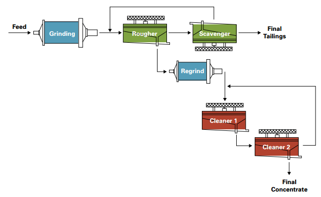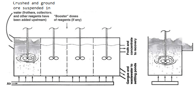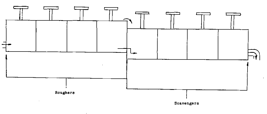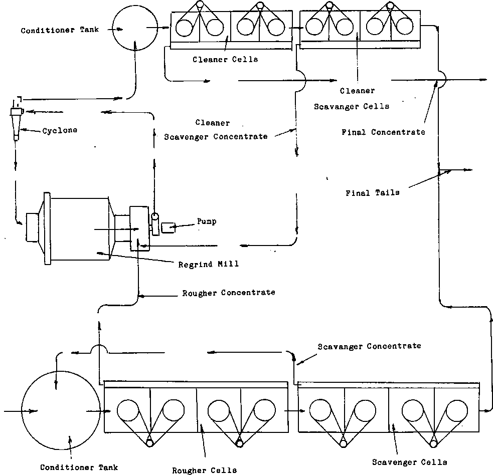
Let’s, proceed to Basic Flotation CIRCUIT DESIGN. To understand flotation it is necessary to learn some new terminology. To do this let’s look at a simple schematic of the circuit we were just working with.
Let’s start with the CLASSIFIER OVERFLOW, once the classifier is finished with it enters the CONDITIONER TANK.
This tank is there to allow the reagents time to become well mixed with the ore and condition it for recovery. The slurry flow then enters the feed end of the flotation cells. The slurry at this point is called the HEADS of the circuit.
 The mineral is then separated and flows over the overflow into a trough called a flotation cell LAUNDERER. The OVERFLOW is now called the flotation CONCENTRATE of the circuit. The mineral has been separated from the ore, there for it is in a concentrated form from the original. The UNDERFLOW is the pulp. When the pulp has had all the mineral extracted from it that the circuit was able to, and is discharged it is then called the flotation TAILINGS of the circuit.
The flotation HEADS, the CONCENTRATE and the TAILINGS are the most important samples for the flotation operator that are taken. The assays from these will tell the operator the amount of valuable mineral coming in to the circuit. The amount that went out of the circuit. And how well it was separated from the waste. By knowing the heads and the tails it is a simple mathematical formula to determine the percentage of recovered mineral.
Often one bank of these cells will not be enough to recover the necessary amount of mineral. There will have to be another bank of cells added.

These would be called the SCAVENGER cells because they gather the left over mineral from the tails of the first bank of cells. The tails when they enter the feed end of the scavenger cells become the SCAVENGER HEADS. Because the amount of mineral that is in the scavenger concentrate is’ very small in relation to the waste that was gathered, it is often returned to the feed of the original bank of cells to be processed again. The second trip through will increase the volume of feed that the cells must process. In doing so it increases the froth load and increases the chances that the particle will be supported long enough for it to become a concentrate.
If the concentrate from the first set of cells is pure enough to make a final product they will be called the FINAL CONCENTRATE CELLS. On the other hand if the concentrate from these cells still require cleaning they will be called ROUGHER CELLS. This means that to get all of the mineral they had to take a lot of waste rock and unwanted mineral.
In some cases the concentrate from the roughers will simply be re-floated in a set of smaller cells called CLEANERS and CLEANER SCAVENGERS. The concentrate from the cleaners will be the final concentrate while the cleaner scavenger concentrate would go back to the feed of the cleaners. Sometimes the operator will be given an option as to where he should send the tails from a cleaner circuit. Either to final tails to be discarded or back to the rougher circuit to be reprocessed with the new feed coming in. If the latter is the normal procedure it may be due to the mineral not being liberated from the waste well enough to be floated cleanly away from the native rock. When liberation problems are part of the ore’s characteristics the designers of the concentrator plant will include a REGRIND MILL in the Basic Flotation Circuit Design of its flow sheet.
A regrind mill is precisely that, a mill that grinds the material again after it has been concentrated at least once. It is a very small ball mill complete with its own classifier circuit. Liberating the trapped mineral particles isn’t the only thing that a regrind mill will do to aid in the recovery of the mineral. The grinding action of the balls will give fresh surface area free from REAGENT CONTAMINATION. This allows a different combination of reagents to be used to enhance the recovery process.
Before we leave this Basic Flotation Circuit Design section, there are two bits of advice that I would like to pass on, the first is when operating any circuit, allow enough time for any change that you have made to complete its effect on the circuit before initiating another one and the second one is treat the cause not the effect. In other words look for what is causing the problem and fix it instead of simply making the circuit look good.

